
English Manual
Page 2
...nearest SEARS Service Center throughout the United States and SEARS will repair or replace the WEIGHT SYSTEM EXERCISER, free of this manual. This warranty does not apply when the WEIGHT SYSTEM EXERCISER is used commercially or for rental purposes. Remove the PART IDENTIFICATION CHART and... TABLE OF CONTENTS FULL 90 DAY WARRANTY 2 IMPORTANT PRECAUTIONS 3 BEFORE YOU BEGIN 4 ASSEMBLY 5 HOW TO USE THE HOME GYM SYSTEM 26 WEIGHT RESISTANCE CHART 28 TROUBLE-SHOOTING AND MAINTENANCE 29 CABLE DIAGRAMS 30 ORDERING REPLACEMENT PARTS Back Cover Note: A PART IDENTIFICATION CHART and a PART LIST...
...nearest SEARS Service Center throughout the United States and SEARS will repair or replace the WEIGHT SYSTEM EXERCISER, free of this manual. This warranty does not apply when the WEIGHT SYSTEM EXERCISER is used commercially or for rental purposes. Remove the PART IDENTIFICATION CHART and... TABLE OF CONTENTS FULL 90 DAY WARRANTY 2 IMPORTANT PRECAUTIONS 3 BEFORE YOU BEGIN 4 ASSEMBLY 5 HOW TO USE THE HOME GYM SYSTEM 26 WEIGHT RESISTANCE CHART 28 TROUBLE-SHOOTING AND MAINTENANCE 29 CABLE DIAGRAMS 30 ORDERING REPLACEMENT PARTS Back Cover Note: A PART IDENTIFICATION CHART and a PART LIST...
English Manual
Page 3
... arm, butterfly arms, leg lever, leg press plate, lat bar, row bar, ab strap, or nylon strap while weights are adequately informed of this or any commercial, rental or institutional setting. The weights will fall with pre-existing health problems. Read all precautions. 2. SEARS assumes no responsibility for persons over the age...
... arm, butterfly arms, leg lever, leg press plate, lat bar, row bar, ab strap, or nylon strap while weights are adequately informed of this or any commercial, rental or institutional setting. The weights will fall with pre-existing health problems. Read all precautions. 2. SEARS assumes no responsibility for persons over the age...
English Manual
Page 4
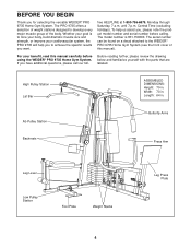
..., please note the product model number and serial number before using the WEIDER® PRO 9735 Home Gym System. Ab Pulley Station Butterfly Arms Backrests Press Arm Leg Lever Low Pulley Station Foot Plate Weight Stacks Leg Press Plate 4 Whether your goal is 831.159390. High ...Pulley Station Lat Bar ASSEMBLED DIMENSIONS: Height: 79 in . To help you to the WEIDER® PRO 9735 Home Gym System (see the front cover of the...
..., please note the product model number and serial number before using the WEIDER® PRO 9735 Home Gym System. Ab Pulley Station Butterfly Arms Backrests Press Arm Leg Lever Low Pulley Station Foot Plate Weight Stacks Leg Press Plate 4 Whether your goal is 831.159390. High ...Pulley Station Lat Bar ASSEMBLED DIMENSIONS: Height: 79 in . To help you to the WEIDER® PRO 9735 Home Gym System (see the front cover of the...

English Manual
Page 5
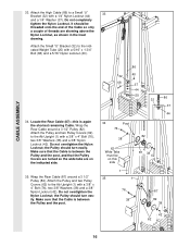
..., and soapy water will be sure that all parts in a cleared area and remove the packing materials; Press three 2" Square Outer Caps (58) onto the Weight Base (14) in the box above. Attach the Press Base (13) to see if it has been pre-attached. • As you have the following... them, unless instructed to do not dispose of the packing materials until you begin each stage is not in the parts bag, check to the Weight Base (14) with two 5/16" x 2 3/4" Bolts (55), two 5/16" Washers (20) and two 5/16" Nylon Locknuts (40). Insert four 5/16" x 2 1/2" Carriage Bolts (49) up through...
..., and soapy water will be sure that all parts in a cleared area and remove the packing materials; Press three 2" Square Outer Caps (58) onto the Weight Base (14) in the box above. Attach the Press Base (13) to see if it has been pre-attached. • As you have the following... them, unless instructed to do not dispose of the packing materials until you begin each stage is not in the parts bag, check to the Weight Base (14) with two 5/16" x 2 3/4" Bolts (55), two 5/16" Washers (20) and two 5/16" Nylon Locknuts (40). Insert four 5/16" x 2 1/2" Carriage Bolts (49) up through...

English Manual
Page 6
...51 79 4 1 51 56 FRAME ASSEMBLY 40 40 4. Slide the Rear Seat Frame (16) onto the indicated 5/16" x 2 1/2" Carriage Bolts (49) in the 3 Weight Base (14). Do not fully tighten the Nylon Locknuts. Slide the Ab Upright (1) onto the indicated 5/16" x 2 1/2" Carriage Bolts (49) in the... Weight Base (14). Partially tighten a 5/16" Nylon Locknut (40) onto each Carriage Bolt. Slide the Leg Press Upright (4) onto the indicated 5/16" x 2 1/2" Carriage Bolts (...
...51 79 4 1 51 56 FRAME ASSEMBLY 40 40 4. Slide the Rear Seat Frame (16) onto the indicated 5/16" x 2 1/2" Carriage Bolts (49) in the 3 Weight Base (14). Do not fully tighten the Nylon Locknuts. Slide the Ab Upright (1) onto the indicated 5/16" x 2 1/2" Carriage Bolts (49) in the... Weight Base (14). Partially tighten a 5/16" Nylon Locknut (40) onto each Carriage Bolt. Slide the Leg Press Upright (4) onto the indicated 5/16" x 2 1/2" Carriage Bolts (...

English Manual
Page 7
... (20) and two 5/16" Nylon Locknuts (40). Be sure that the pin grooves are on the Weight Base (14). Partially tighten a 5/16" Nylon Locknut (40) onto each stack of the Weight Guides (23). Attach the other Weight Guides (23) to the Leg Press Upright (4) with a 5/16" x 6" Bolt (67), two 1/2" x 3/4"... Spacers (69) and a 5/16" Nylon Locknut (40). Press a 2" Square Inner Cap (56) into one of Weight Guides (23). Slide a Weight Bumper (27) onto each of Weights. 5 55 20 40 8 4 56 40 13 49 6 23 23 67 40 14 69 7 90 Pin Grooves 90 Pin Grooves 27 27...
... (20) and two 5/16" Nylon Locknuts (40). Be sure that the pin grooves are on the Weight Base (14). Partially tighten a 5/16" Nylon Locknut (40) onto each stack of the Weight Guides (23). Attach the other Weight Guides (23) to the Leg Press Upright (4) with a 5/16" x 6" Bolt (67), two 1/2" x 3/4"... Spacers (69) and a 5/16" Nylon Locknut (40). Press a 2" Square Inner Cap (56) into one of Weight Guides (23). Slide a Weight Bumper (27) onto each of Weights. 5 55 20 40 8 4 56 40 13 49 6 23 23 67 40 14 69 7 90 Pin Grooves 90 Pin Grooves 27 27...

English Manual
Page 8
Press a Weight Tube Bumper (26) into each stack of Weights (90). Lubricate the insides of Weight Guides (23). 24 Lubricate 23 23 Lubricate 24 8 Insert a Weight Tube (25) into each set of the holes in the upper Weights. 25 26 90 90 FRAME ASSEMBLY 9. Be sure that the pins on the Weight Tubes are in the pin grooves in the Top 9 Weights (24) as shown. 8. Slide a Top Weight onto each 8 Weight Tube (25).
Press a Weight Tube Bumper (26) into each stack of Weights (90). Lubricate the insides of Weight Guides (23). 24 Lubricate 23 23 Lubricate 24 8 Insert a Weight Tube (25) into each set of the holes in the upper Weights. 25 26 90 90 FRAME ASSEMBLY 9. Be sure that the pins on the Weight Tubes are in the pin grooves in the Top 9 Weights (24) as shown. 8. Slide a Top Weight onto each 8 Weight Tube (25).

English Manual
Page 9
... Support Plate (98) and two 5/16" Nylon Locknuts (40). Do not tighten the Nylon Locknuts yet. 12. Attach the upper ends of one set of Weight Guides (23) in steps 2 through 12. 10 2 56 40 20 20 56 55 70 55 56 56 3 11 55 20 2 92 3 98 40 1 12 40... the same manner. Press a 2" Square Inner Cap (56) into each side of the Butterfly Frame. Press two 1" Round Inner Caps (70) into each end of Weight Guides (23) to the Ab Upright (1) with a 5/16" x 6" Bolt (67), two 1/2" x 3/4" Spacers (69) and a 5/16" Nylon Locknut (40). Press a 2" Square Inner Cap (56) into the...
... Support Plate (98) and two 5/16" Nylon Locknuts (40). Do not tighten the Nylon Locknuts yet. 12. Attach the upper ends of one set of Weight Guides (23) in steps 2 through 12. 10 2 56 40 20 20 56 55 70 55 56 56 3 11 55 20 2 92 3 98 40 1 12 40... the same manner. Press a 2" Square Inner Cap (56) into each side of the Butterfly Frame. Press two 1" Round Inner Caps (70) into each end of Weight Guides (23) to the Ab Upright (1) with a 5/16" x 6" Bolt (67), two 1/2" x 3/4" Spacers (69) and a 5/16" Nylon Locknut (40). Press a 2" Square Inner Cap (56) into the...
English Manual
Page 16
... shortest remaining Cable. Do not overtighten the Nylon Locknut; the Pulley should turn easily. Attach the Pulley and two Pulley Covers (62) to the indicated Weight Tube (25) with a 3/8" x 4" Bolt (76), two 3/8" Washers (38) and a 3/8" Nylon Locknut (42). the Pulley should turn easily. Wrap the Rear Cable around a 3 1/2" Pulley (82). It...
... shortest remaining Cable. Do not overtighten the Nylon Locknut; the Pulley should turn easily. Attach the Pulley and two Pulley Covers (62) to the indicated Weight Tube (25) with a 3/8" x 4" Bolt (76), two 3/8" Washers (38) and a 3/8" Nylon Locknut (42). the Pulley should turn easily. Wrap the Rear Cable around a 3 1/2" Pulley (82). It...
English Manual
Page 18
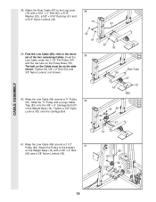
Attach the Rear Cable (87) to the bracket 41 on the Weight Base (14) with a 5/16" x 3" Bolt (92), a 5/16" Washer (20), a 5/8" x 9/16" Bushing (61) and a 5/16" Nylon Locknut (40). 15 87 39. Tighten...around a 3 1/2" Pulley (82). Slide the "V" Pulley and a Large Cable Trap (83) onto the 3/8" x 4" Carriage Bolt (57) in the Weight Base (14). Tighten a 3/8" Nylon Locknut (42) onto the Carriage Bolt. 40 61 39 20 92 89 50 40 42 89 83 81 57 Row ...ball on the Cable must be on the Pulley Base (79). Feed the Low Cable under the 3 1/2" Pro Pulley (97) and the row tube on the side shown.
Attach the Rear Cable (87) to the bracket 41 on the Weight Base (14) with a 5/16" x 3" Bolt (92), a 5/16" Washer (20), a 5/8" x 9/16" Bushing (61) and a 5/16" Nylon Locknut (40). 15 87 39. Tighten...around a 3 1/2" Pulley (82). Slide the "V" Pulley and a Large Cable Trap (83) onto the 3/8" x 4" Carriage Bolt (57) in the Weight Base (14). Tighten a 3/8" Nylon Locknut (42) onto the Carriage Bolt. 40 61 39 20 92 89 50 40 42 89 83 81 57 Row ...ball on the Cable must be on the Pulley Base (79). Feed the Low Cable under the 3 1/2" Pro Pulley (97) and the row tube on the side shown.

English Manual
Page 20
... the inset drawing. Do not completely tighten the Nylon Locknut. Route the Press Cable (88) around the 3 1/2" Pulley (82) attached to the indi- 32 cated Weight Tube (25) with a 5/16" x 1 3/4" Bolt (68) and a 5/16" Nylon Locknut (40). 46. Be sure that the Cable Trap (80) is in this step is shown...
... the inset drawing. Do not completely tighten the Nylon Locknut. Route the Press Cable (88) around the 3 1/2" Pulley (82) attached to the indi- 32 cated Weight Tube (25) with a 5/16" x 1 3/4" Bolt (68) and a 5/16" Nylon Locknut (40). 46. Be sure that the Cable Trap (80) is in this step is shown...

English Manual
Page 25
... ARM PRESS LEG PRESS SERIAL NUMBER DECAL LOW PULLEY/ROW 65. IMPORTANT: If the cables are not properly installed, they may be damaged when heavy weight is any slack in HOW TO USE THE HOME GYM SYSTEM, beginning on page 29. 25 See TROUBLE-SHOOTING AND MAINTENANCE on page 26 of...
... ARM PRESS LEG PRESS SERIAL NUMBER DECAL LOW PULLEY/ROW 65. IMPORTANT: If the cables are not properly installed, they may be damaged when heavy weight is any slack in HOW TO USE THE HOME GYM SYSTEM, beginning on page 29. 25 See TROUBLE-SHOOTING AND MAINTENANCE on page 26 of...
English Manual
Page 26
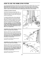
...WEIGHT SETTING The PRO 9735 features two weight stacks. One weight stack is connected to the butterfly and press arms, the leg press, and the low pulley station. 93 To change the weight setting of the Weight Pin is touching the Weights and turn the bent end downward. Insert the Weight Pin until the bent end of either weight...the Lat Bar is in the correct starting position for each exercise. The weight setting of either weight stack, insert a Weight Pin (93) under the desired Weight (90). Use the WEIGHT RESISTANCE CHART on page 28 to find the approximate amount of resistance at ...
...WEIGHT SETTING The PRO 9735 features two weight stacks. One weight stack is connected to the butterfly and press arms, the leg press, and the low pulley station. 93 To change the weight setting of the Weight Pin is touching the Weights and turn the bent end downward. Insert the Weight Pin until the bent end of either weight...the Lat Bar is in the correct starting position for each exercise. The weight setting of either weight stack, insert a Weight Pin (93) under the desired Weight (90). Use the WEIGHT RESISTANCE CHART on page 28 to find the approximate amount of resistance at ...

English Manual
Page 28
... numbers refer to the 6.5 lb. WEIGHT RESISTANCE CHART This chart shows the approximate weight resistance at each weight station may vary due to differences in individual weight plates, as well as friction between the cables, pulleys and weight guides. 28 The butterfly arm resistance is the resistance for each weight station. weight plates. WEIGHT PLATES Top 1 2 3 4 5 6 7 8 PRESS ARM...
... numbers refer to the 6.5 lb. WEIGHT RESISTANCE CHART This chart shows the approximate weight resistance at each weight station may vary due to differences in individual weight plates, as well as friction between the cables, pulleys and weight guides. 28 The butterfly arm resistance is the resistance for each weight station. weight plates. WEIGHT PLATES Top 1 2 3 4 5 6 7 8 PRESS ARM...
English Manual
Page 29
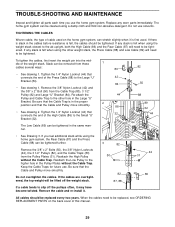
...the home gym system. Reattach the Low Pulley to be tightened. If the cables are overtightened, the top weight will need to the higher hole in the Large "U" Bracket. When the cables need to be removed from...80 • See drawing 1. If there is slack in the cables before resistance is felt when using the weight stack closest to the ab upright, both the High Cable (86) and the Rear Cable (87) will... need to be tightened. To tighten the cables, first insert the weight pin into the middle of the Press Cable (88) to the Small "U" 32 44 Bracket (32). 44...
...the home gym system. Reattach the Low Pulley to be tightened. If the cables are overtightened, the top weight will need to the higher hole in the Large "U" Bracket. When the cables need to be removed from...80 • See drawing 1. If there is slack in the cables before resistance is felt when using the weight stack closest to the ab upright, both the High Cable (86) and the Rear Cable (87) will... need to be tightened. To tighten the cables, first insert the weight pin into the middle of the Press Cable (88) to the Small "U" 32 44 Bracket (32). 44...
English Manual
Page 30
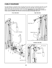
... labeled. Use the diagrams to be sure that the Cables have not been correctly routed, the WEIDER PRO 9735 will not function properly and damage may occur. Press Cable (88) High Cable (86) 4 2 3 High Pulley-1 1-Long "U" Bracket 4 Weight Stack-5 5 76 11 8 2 3 9 12 10 Leg Press-13 30 Butterfly Cable (85) 4 5-Left Arm 2 1-Right Arm...
... labeled. Use the diagrams to be sure that the Cables have not been correctly routed, the WEIDER PRO 9735 will not function properly and damage may occur. Press Cable (88) High Cable (86) 4 2 3 High Pulley-1 1-Long "U" Bracket 4 Weight Stack-5 5 76 11 8 2 3 9 12 10 Leg Press-13 30 Butterfly Cable (85) 4 5-Left Arm 2 1-Right Arm...

English Manual
Page 31
Low Cable (89) 6 4 5 Weight Stack-7 Rear Cable (87) 3 Ab Pulley-1 2 5-Leg Lever 3 4 1-Low Pulley 2 31
Low Cable (89) 6 4 5 Weight Stack-7 Rear Cable (87) 3 Ab Pulley-1 2 5-Leg Lever 3 4 1-Low Pulley 2 31
English Manual
Page 34
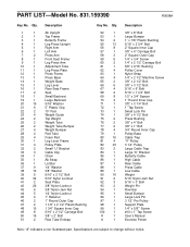
...Pulley 3 1/2" Pulley Large Cable Trap Large "U" Bracket Butterfly Cable High Cable Rear Cable Press Cable Low Cable Weight 5/16" Nylon Jam Nut 5/16" x 3" Bolt Weight Pin Row Bar Small Bumper Large Lock Pin 3 1/2" Pro Pulley Support Plate 1/4" x 5/8"" Screw #10 x 1" Tap Screw User's Manual Exercise Poster Note: "#" ...Arm Adjustment Tube Leg Press Plate Press Frame Press Base Weight Base Leg Lever Rear Seat Frame Seat Small Backrest Large Backrest 5/16" Washer 5" Plastic Grip 10" Pad Weight Guide Top Weight Weight Tube Weight Tube Bumper Weight Bumper Pad Tube Foam Pad Leg Lever Frame Pulley ...
...Pulley 3 1/2" Pulley Large Cable Trap Large "U" Bracket Butterfly Cable High Cable Rear Cable Press Cable Low Cable Weight 5/16" Nylon Jam Nut 5/16" x 3" Bolt Weight Pin Row Bar Small Bumper Large Lock Pin 3 1/2" Pro Pulley Support Plate 1/4" x 5/8"" Screw #10 x 1" Tap Screw User's Manual Exercise Poster Note: "#" ...Arm Adjustment Tube Leg Press Plate Press Frame Press Base Weight Base Leg Lever Rear Seat Frame Seat Small Backrest Large Backrest 5/16" Washer 5" Plastic Grip 10" Pad Weight Guide Top Weight Weight Tube Weight Tube Bumper Weight Bumper Pad Tube Foam Pad Leg Lever Frame Pulley ...


