

English Manual
Page 2
... of the pulleys 13. At.olwnawYhs ewneeaxr eartchilseitnicg.shoes for protection. 5. The home gym system is designed to ensure that the cables remain on,the P lerys at all instructions in the accompanying literature before using. Do not use the lat bar. 4. This is...injury, read the following important precautions before beginning assembly. TABLE OF CONTENTS IMPORTANT PRECAUTIONS BEFORE YOU BEGIN ASSEMBLY ADJUSTMENT TROUBLE-SHOOTING AND MAINTENANCE CABLE DIAGRAM ORDERING REPLACEMENT PARTS FULL 90 DAY WARRANTY 2 3 4 19 22 23 Back Cover Back Cover Note: An EXPLODED DRAWING/PART LIST...
... of the pulleys 13. At.olwnawYhs ewneeaxr eartchilseitnicg.shoes for protection. 5. The home gym system is designed to ensure that the cables remain on,the P lerys at all instructions in the accompanying literature before using. Do not use the lat bar. 4. This is...injury, read the following important precautions before beginning assembly. TABLE OF CONTENTS IMPORTANT PRECAUTIONS BEFORE YOU BEGIN ASSEMBLY ADJUSTMENT TROUBLE-SHOOTING AND MAINTENANCE CABLE DIAGRAM ORDERING REPLACEMENT PARTS FULL 90 DAY WARRANTY 2 3 4 19 22 23 Back Cover Back Cover Note: An EXPLODED DRAWING/PART LIST...

English Manual
Page 9
... place. 7---4 6 54 -50 23 42 17. Attach the Pulley to hold the Cable in place. Route the Medium Cable (23) around a 3 1/2" Pulley (15). Be sure that the Long Cable Trap (50) is positioned to verify proper cable routing. Tighten the 3/8" x 2 1/2" Bolt (7) and the 3/8" Nylon Locknut (not shown). ... Long Cable Trap is positioned to the Top Frame (55) with a 3/8" x 2 1/2" Bolt (7) and a 3/8" Nylon Locknut (21). IMPORTANT: While assembling the cables, do not overtighten the bolts and nuts securing the pulleys. During steps 15 through 36, refer to the CABLE DIAGRAM on ...
... place. 7---4 6 54 -50 23 42 17. Attach the Pulley to hold the Cable in place. Route the Medium Cable (23) around a 3 1/2" Pulley (15). Be sure that the Long Cable Trap (50) is positioned to verify proper cable routing. Tighten the 3/8" x 2 1/2" Bolt (7) and the 3/8" Nylon Locknut (not shown). ... Long Cable Trap is positioned to the Top Frame (55) with a 3/8" x 2 1/2" Bolt (7) and a 3/8" Nylon Locknut (21). IMPORTANT: While assembling the cables, do not overtighten the bolts and nuts securing the pulleys. During steps 15 through 36, refer to the CABLE DIAGRAM on ...
English Manual
Page 18
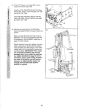
...of the Pad Tube. 45. If there is used. IMPORTANT: If the cables are not properly installed, they may be sure that all parts have been properly tightened. See the CABLE DIAGRAM on page 22. 0 36 30 34 28 34 0 0 0 29 30 PRO 9625 VII c!) O) 6 ) 18 Insert the other Pad Tube (28) ...into the Front Seat Frame (36). Make sure that the cables move smoothly, find and correct the problem. If one...
...of the Pad Tube. 45. If there is used. IMPORTANT: If the cables are not properly installed, they may be sure that all parts have been properly tightened. See the CABLE DIAGRAM on page 22. 0 36 30 34 28 34 0 0 0 29 30 PRO 9625 VII c!) O) 6 ) 18 Insert the other Pad Tube (28) ...into the Front Seat Frame (36). Make sure that the cables move smoothly, find and correct the problem. If one...

English Manual
Page 23
... damage may occur. If the cables have been assembled correctly. Use the diagram to be sure that the cable traps do not touch or bind the cables. 7 2 1-High Pulley Medium Cable (23) 8 qa) 3 5 4 6 2 Short Cable (58) Rear Upright-1 0 7 ,_____.9-Weight Stack Long "U"-Bracket-3 Long Cable (86) 9 Base-10 6 4 3 8 2 5 -Low Pulley 23 CABLE DIAGRAM The cable diagram below shows the proper routing...
... damage may occur. If the cables have been assembled correctly. Use the diagram to be sure that the cable traps do not touch or bind the cables. 7 2 1-High Pulley Medium Cable (23) 8 qa) 3 5 4 6 2 Short Cable (58) Rear Upright-1 0 7 ,_____.9-Weight Stack Long "U"-Bracket-3 Long Cable (86) 9 Base-10 6 4 3 8 2 5 -Low Pulley 23 CABLE DIAGRAM The cable diagram below shows the proper routing...


