
Uk Manual
Page 2
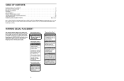
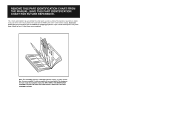
... a free replacement decal. TABLE OF CONTENTS WARNING DECAL PLACEMENT 2 IMPORTANT PRECAUTIONS 3 BEFORE YOU BEGIN 4 ASSEMBLY 5 ADJUSTMENTS 21 WEIGHT RESISTANCE CHART 23 TROUBLESHOOTING AND MAINTENANCE 24 CABLE DIAGRAMS 25 ORDERING REPLACEMENT PARTS Back Cover Note: A PART IDENTIFICATION CHART and a PART LIST/EXPLODED DRAWING are attached at the centre of this product may...
... a free replacement decal. TABLE OF CONTENTS WARNING DECAL PLACEMENT 2 IMPORTANT PRECAUTIONS 3 BEFORE YOU BEGIN 4 ASSEMBLY 5 ADJUSTMENTS 21 WEIGHT RESISTANCE CHART 23 TROUBLESHOOTING AND MAINTENANCE 24 CABLE DIAGRAMS 25 ORDERING REPLACEMENT PARTS Back Cover Note: A PART IDENTIFICATION CHART and a PART LIST/EXPLODED DRAWING are attached at the centre of this product may...
Uk Manual
Page 3
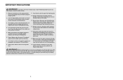
... at all instructions in this manual and in an commercial, rental, or institutional setting. 4. Make sure that the cables remain on a foot plate when performing an exercise that the cables are raised. If the cables bind whilst you are exercising, stop immediately and begin cooling down. It is the responsibility of all times...
... at all instructions in this manual and in an commercial, rental, or institutional setting. 4. Make sure that the cables remain on a foot plate when performing an exercise that the cables are raised. If the cables bind whilst you are exercising, stop immediately and begin cooling down. It is the responsibility of all times...
Uk Manual
Page 5
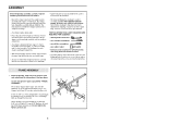
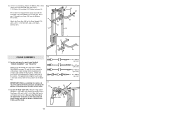
... several hours. Do not tighten the Nylon Locknuts yet. 5 51 11 8 1 3 1 4 51 1 27 5 Press a 2" Square Inner Cap (27) into four stages: 1) frame assembly, 2) arm assembly, 3) cable assembly, and 4) seat assembly. Press two 2" Square Outer Caps (51) onto the Stabiliser (5) in the centre of ratchet wrenches. If a part is divided into the...
... several hours. Do not tighten the Nylon Locknuts yet. 5 51 11 8 1 3 1 4 51 1 27 5 Press a 2" Square Inner Cap (27) into four stages: 1) frame assembly, 2) arm assembly, 3) cable assembly, and 4) seat assembly. Press two 2" Square Outer Caps (51) onto the Stabiliser (5) in the centre of ratchet wrenches. If a part is divided into the...
Uk Manual
Page 10
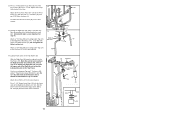
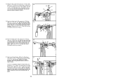
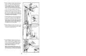
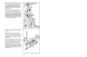
... Arm. 44 49 Attach the Press Arm (46) to one of the Right Arm is very important for step 14. Attach a "V"-Pulley (50) and a Long Cable Trap (31) to confuse the Right Arm with a 3/8" x 2 1/2" Bolt (86) and a 3/8" Nylon Locknut (21). Do not tighten the Nylon Locknut yet. 13 86 31 50... Welded Brackets 31 50 47 21 Attach a "V"-Pulley (50) and a Long Cable Trap (31) to identify the Right Arm. See the inset drawing. Be 48 sure that the upper end of the 12 Press Arms (46). Note...
... Arm. 44 49 Attach the Press Arm (46) to one of the Right Arm is very important for step 14. Attach a "V"-Pulley (50) and a Long Cable Trap (31) to confuse the Right Arm with a 3/8" x 2 1/2" Bolt (86) and a 3/8" Nylon Locknut (21). Do not tighten the Nylon Locknut yet. 13 86 31 50... Welded Brackets 31 50 47 21 Attach a "V"-Pulley (50) and a Long Cable Trap (31) to identify the Right Arm. See the inset drawing. Be 48 sure that the upper end of the 12 Press Arms (46). Note...
Uk Manual
Page 11
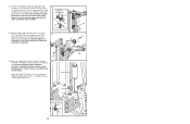
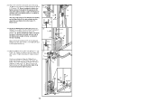
...). Attach the Military Press Arm 15 (84) to the Top Frame (55) with two 5/16" x 2 1/4" Bolts (33) and two 5/16" Nylon Locknuts (3). Identify the four Cables by comparing the lengths and ends of each Cable is listed (in inches) after the key number in the drawing. The approximate length of the... Arm (84). Press two 1" Round Inner Caps (49) into the indicated end of the Pulley and that the Cable is on pages 25 and 26 of this section, fully unwind the four Cables. the pulleys must be able to the Rear Upright (74) with the ball is between the Pulley and the...
...). Attach the Military Press Arm 15 (84) to the Top Frame (55) with two 5/16" x 2 1/4" Bolts (33) and two 5/16" Nylon Locknuts (3). Identify the four Cables by comparing the lengths and ends of each Cable is listed (in inches) after the key number in the drawing. The approximate length of the... Arm (84). Press two 1" Round Inner Caps (49) into the indicated end of the Pulley and that the Cable is on pages 25 and 26 of this section, fully unwind the four Cables. the pulleys must be able to the Rear Upright (74) with the ball is between the Pulley and the...
Uk Manual
Page 12
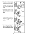
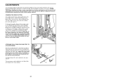
...) on the Left Arm (47). Be sure that the Cable 19 is in the groove of the Pulley and that the Cable Trap (66) is positioned to hold the Cable in place. Route the High Cable (58) around a "V"-Pulley (50). 18 Attach the "V"-Pulley and a Long Cable Trap (31) to the Top Frame (55) with...) around the 3 1/2" Pulley (15) attached to move freely. Be sure that the Cable 20 is in the groove of the Pulley and that the Long Cable Trap (31) is turned to hold the Cable in place. 19. Tighten the 3/8" x 2 1/2" Bolt (86) and the 3/8" Nylon Locknut (not shown). 31 86 50 58 48 21...
...) on the Left Arm (47). Be sure that the Cable 19 is in the groove of the Pulley and that the Cable Trap (66) is positioned to hold the Cable in place. Route the High Cable (58) around a "V"-Pulley (50). 18 Attach the "V"-Pulley and a Long Cable Trap (31) to the Top Frame (55) with...) around the 3 1/2" Pulley (15) attached to move freely. Be sure that the Cable 20 is in the groove of the Pulley and that the Long Cable Trap (31) is turned to hold the Cable in place. 19. Tighten the 3/8" x 2 1/2" Bolt (86) and the 3/8" Nylon Locknut (not shown). 31 86 50 58 48 21...
Uk Manual
Page 13
... 63 71 58 10 2 13 55 24 10 2 Do not completely tighten the Nylon Locknut. Note: This may be threaded onto the end of the Cable only a couple of turns, as shown in the inset drawing. 58 Attach the Small "U"-Bracket (71) to the bracket on the Pulley Covers are in... the position shown and that the Cable and Pulley move smoothly. 58 Bracket 15 58 57 12 15 21 24. Attach the Pulley to the indicated Weight Tube (63) with a 3/8" x 2" Bolt (12...
... 63 71 58 10 2 13 55 24 10 2 Do not completely tighten the Nylon Locknut. Note: This may be threaded onto the end of the Cable only a couple of turns, as shown in the inset drawing. 58 Attach the Small "U"-Bracket (71) to the bracket on the Pulley Covers are in... the position shown and that the Cable and Pulley move smoothly. 58 Bracket 15 58 57 12 15 21 24. Attach the Pulley to the indicated Weight Tube (63) with a 3/8" x 2" Bolt (12...
Uk Manual
Page 14
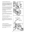
... Press Frame, between the Pulley and the crossbar. 25 23 Crossbar 76 Ball 17 88 9 7 17 76 21 26. Attach the Pulley, a set of the Cable with a 3/8" Nylon Locknut (21) and a 3/8" x 3 1/2" Bolt (16). tion shown. 23 16 9 15 28. Attach the Pulley and the 5/8" x 9/16" Spacer (7) to the upper hole in... position. 17 28 42 9 88 77-Large 21 9 tabs should be here. 23 77-Small tabs should be here. 9 99 15 14 Locate the Low Cable (23) and the bag labelled "LOW PULLEY." Be sure that the large tabs on the Pulley Covers are oriented as shown in the Front Upright...
... Press Frame, between the Pulley and the crossbar. 25 23 Crossbar 76 Ball 17 88 9 7 17 76 21 26. Attach the Pulley, a set of the Cable with a 3/8" Nylon Locknut (21) and a 3/8" x 3 1/2" Bolt (16). tion shown. 23 16 9 15 28. Attach the Pulley and the 5/8" x 9/16" Spacer (7) to the upper hole in... position. 17 28 42 9 88 77-Large 21 9 tabs should be here. 23 77-Small tabs should be here. 9 99 15 14 Locate the Low Cable (23) and the bag labelled "LOW PULLEY." Be sure that the large tabs on the Pulley Covers are oriented as shown in the Front Upright...
Uk Manual
Page 15
The number in parenthesis below each stage is divided into four stages: 1) frame assembly, 2) arm assembly, 3) cable assembly, 4) seat assembly. The hardware for shipping purposes. This chart is provided to help you cannot find a part in the parts bags, check to the ...
The number in parenthesis below each stage is divided into four stages: 1) frame assembly, 2) arm assembly, 3) cable assembly, 4) seat assembly. The hardware for shipping purposes. This chart is provided to help you cannot find a part in the parts bags, check to the ...
Uk Manual
Page 16
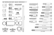
... Lock Nut (21) 3/8" Nylon Jam Nut (99) 5/16" x 1 3/4" Bolt (24) 5/16" Nylon Locknut (3) #8 x 1/2" Selftapping Screw (87) 5/16" Nylon Jam Nut (93) 1/4" x 3/4" Screw (18) 1/4" Nylon Locknut (2) Cable Clip (53) 3/8" x 8" Bolt (59) 1 1/8" x 2 1/2" Plastic Bushing (89) 1" x 7/8" Plastic Bushing (90) 5/16" x 2 1/2" Carriage Bolt (1) 5/16" x 2 1/2" Bolt (22) 1/4" x 2 1/2" Carriage Bolt (92) 1/4" x 2 1/2" Screw (43) 5/16" x 2 1/4" Bolt (33) 1/4" x 2" Carriage...
... Lock Nut (21) 3/8" Nylon Jam Nut (99) 5/16" x 1 3/4" Bolt (24) 5/16" Nylon Locknut (3) #8 x 1/2" Selftapping Screw (87) 5/16" Nylon Jam Nut (93) 1/4" x 3/4" Screw (18) 1/4" Nylon Locknut (2) Cable Clip (53) 3/8" x 8" Bolt (59) 1 1/8" x 2 1/2" Plastic Bushing (89) 1" x 7/8" Plastic Bushing (90) 5/16" x 2 1/2" Carriage Bolt (1) 5/16" x 2 1/2" Bolt (22) 1/4" x 2 1/2" Carriage Bolt (92) 1/4" x 2 1/2" Screw (43) 5/16" x 2 1/4" Bolt (33) 1/4" x 2" Carriage...

Uk Manual
Page 19
...3/8" x 3 1/2" Bolt Press Frame 1/4" x 3/4" Screw Weight Bumper Pulley Bracket 3/8" Nylon Locknut 5/16" x 2 1/2" Bolt Low Cable 5/16" x 1 3/4" Bolt Weight Weight Pin 2" Square Inner Cap Pad Tube Leg Lever Foam Pad Long Cable Trap 1 1/2" Square Inner Cap 5/16" x 2 1/4" Bolt 3/4" Round Inner Cap 3/8" x 2" Eyebolt Front Seat Frame Seat Plate... Short Weight Guide 74 1 Rear Upright 75 2 Round Inner Cap 76 1 3 1/2" Low Pulley 77 20 Pulley Cover 78 1 Leg Press Cable 79 1 Leg Press Seat Frame 80 1 Pivot Arm 81 1 1/4" x 2" Machine Screw 82 1 Handle 83 8 5" Plastic Grip 84 ...
...3/8" x 3 1/2" Bolt Press Frame 1/4" x 3/4" Screw Weight Bumper Pulley Bracket 3/8" Nylon Locknut 5/16" x 2 1/2" Bolt Low Cable 5/16" x 1 3/4" Bolt Weight Weight Pin 2" Square Inner Cap Pad Tube Leg Lever Foam Pad Long Cable Trap 1 1/2" Square Inner Cap 5/16" x 2 1/4" Bolt 3/4" Round Inner Cap 3/8" x 2" Eyebolt Front Seat Frame Seat Plate... Short Weight Guide 74 1 Rear Upright 75 2 Round Inner Cap 76 1 3 1/2" Low Pulley 77 20 Pulley Cover 78 1 Leg Press Cable 79 1 Leg Press Seat Frame 80 1 Pivot Arm 81 1 1/4" x 2" Machine Screw 82 1 Handle 83 8 5" Plastic Grip 84 ...
Uk Manual
Page 22
...other Small "U"-Bracket (71) with a 3/8" x 2" Bolt (12) and a 3/8" Nylon Locknut (21). Do not completely tighten the Nylon Locknut. Wrap the Military Press Cable (72) around a 3 1/2" Pulley (15). Attach the end of threads are showing above the Nylon Locknut, as shown in the inset drawing. Attach the Military Press... 24 10 2 12 66 15 72 Bracket 21 5 15 See the inset drawing. Attach the Pulley and a Cable Trap (66) to the bracket on the High Cable (58) to get enough slack to attach the Low Cable (23) to the Long "U"-Bracket (57) with a 5/16" x 1 3/4" Bolt (24) and a 5/16" Nylon ...
...other Small "U"-Bracket (71) with a 3/8" x 2" Bolt (12) and a 3/8" Nylon Locknut (21). Do not completely tighten the Nylon Locknut. Wrap the Military Press Cable (72) around a 3 1/2" Pulley (15). Attach the end of threads are showing above the Nylon Locknut, as shown in the inset drawing. Attach the Military Press... 24 10 2 12 66 15 72 Bracket 21 5 15 See the inset drawing. Attach the Pulley and a Cable Trap (66) to the bracket on the High Cable (58) to get enough slack to attach the Low Cable (23) to the Long "U"-Bracket (57) with a 5/16" x 1 3/4" Bolt (24) and a 5/16" Nylon ...
Uk Manual
Page 23
... Arm (80) with a 3/8" Washer (9) and a 3/8" Nylon Locknut (21). Make sure that the large tabs on the Pulley Covers are on top. Wrap the Military Press Cable (72) around a 3 1/2" Pulley (15). See the inset drawing. Attach the Pulley and a pair of Pulley Covers (77) to the 3/8" x 5 1/4" Bolt (101)...pair of Pulley Covers (77) to the Leg Press Upright (56) with the 3/8" Washer (9) and the 3/8" x 5 1/4" Bolt (101). Wrap the Military Press Cable (72) around a 3 1/2" 33 Pulley (15). Make sure the large tabs on the Pulley Covers are on the other side of Pulley Covers (77) to the...
... Arm (80) with a 3/8" Washer (9) and a 3/8" Nylon Locknut (21). Make sure that the large tabs on the Pulley Covers are on top. Wrap the Military Press Cable (72) around a 3 1/2" Pulley (15). See the inset drawing. Attach the Pulley and a pair of Pulley Covers (77) to the 3/8" x 5 1/4" Bolt (101)...pair of Pulley Covers (77) to the Leg Press Upright (56) with the 3/8" Washer (9) and the 3/8" x 5 1/4" Bolt (101). Wrap the Military Press Cable (72) around a 3 1/2" 33 Pulley (15). Make sure the large tabs on the Pulley Covers are on the other side of Pulley Covers (77) to the...
Uk Manual
Page 24
... the Long "U"-Bracket (57) with a 3/8" x 2" Bolt (12) and a 3/8" Nylon Jam Nut (99). Attach the Pulley and a set of the Leg Press Cable to pivot. 2 10 57 96 Small 99 12 11 Tab 77 8 78 100 15 94 99 77 8 79 93 17 Do not fully tighten the ... Press Bracket (94) to the Press Bracket (94) with a 1/4" Nylon Locknut (2) and a 1/4" Washer (10). Be sure that the Cable and Pulley move smoothly and that the Cable is between the two Jam Nuts for cable adjustment.) Tighten a 5/16" Washer (8) and a 5/16" Nylon Jam Nut (93) onto the Bolt. Thread another 5/16" Nylon Jam...
... the Long "U"-Bracket (57) with a 3/8" x 2" Bolt (12) and a 3/8" Nylon Jam Nut (99). Attach the Pulley and a set of the Leg Press Cable to pivot. 2 10 57 96 Small 99 12 11 Tab 77 8 78 100 15 94 99 77 8 79 93 17 Do not fully tighten the ... Press Bracket (94) to the Press Bracket (94) with a 1/4" Nylon Locknut (2) and a 1/4" Washer (10). Be sure that the Cable and Pulley move smoothly and that the Cable is between the two Jam Nuts for cable adjustment.) Tighten a 5/16" Washer (8) and a 5/16" Nylon Jam Nut (93) onto the Bolt. Thread another 5/16" Nylon Jam...
Uk Manual
Page 27
Before using the weight system, pull each cable a few times to remove it by tightening the cables. If there is used. 44. The use of this manual for proper cable routing. If one of this manual. See the CABLE DIAGRAMS on page 25 and 26 of the cables does not move smoothly over the pulleys....21 of the remaining parts will need to be sure that all parts have been properly tightened. IMPORTANT: If the cables are not properly installed, they may be explained in the cables, you will be damaged when heavy weight is any slack in ADJUSTMENTS, beginning on page 24. 20 Make sure ...
Before using the weight system, pull each cable a few times to remove it by tightening the cables. If there is used. 44. The use of this manual for proper cable routing. If one of this manual. See the CABLE DIAGRAMS on page 25 and 26 of the cables does not move smoothly over the pulleys....21 of the remaining parts will need to be sure that all parts have been properly tightened. IMPORTANT: If the cables are not properly installed, they may be explained in the cables, you will be damaged when heavy weight is any slack in ADJUSTMENTS, beginning on page 24. 20 Make sure ...
Uk Manual
Page 28
...lat bar or nylon strap, make sure that the attachments are in the correct starting position for the exercise to 106.5 pounds, in the cables or chain as an exercise is connected to the upper and lower pulleys, the press arm, and the butterfly arms. The rear weight stack... reduced. CHANGING THE WEIGHT SETTING The weight system features two weight stacks. Refer to the exercise guide accompanying this manual to the Low Cable (23) with two Cable Clips. tance at each exercise station may vary from 6.5 pounds to be performed. ADJUSTMENTS The instructions below describe how each part of...
...lat bar or nylon strap, make sure that the attachments are in the correct starting position for the exercise to 106.5 pounds, in the cables or chain as an exercise is connected to the upper and lower pulleys, the press arm, and the butterfly arms. The rear weight stack... reduced. CHANGING THE WEIGHT SETTING The weight system features two weight stacks. Refer to the exercise guide accompanying this manual to the Low Cable (23) with two Cable Clips. tance at each exercise station may vary from 6.5 pounds to be performed. ADJUSTMENTS The instructions below describe how each part of...
Uk Manual
Page 29
... Front Upright (42). Align the welded tubes on the Leg Press Plate (95) with the desired set of the Chain to the 3/8" x 2" Eyebolt (35) with a Cable Clip. Re-insert the Press Pin (97) through the welded tubes on Leg Press Plate and the holes in the Leg Press Arm. 42 8 40... pin on the Front Upright (42). (Note: The Seat can be attached at three different heights.) Secure the Front Seat Frame to the Low Cable (23) with a Cable Clip (53). Attach one of the Chain (52) to the Front Upright with the Lock (105). For some exercises, the Seat (13) must be...
... Front Upright (42). Align the welded tubes on the Leg Press Plate (95) with the desired set of the Chain to the 3/8" x 2" Eyebolt (35) with a Cable Clip. Re-insert the Press Pin (97) through the welded tubes on Leg Press Plate and the holes in the Leg Press Arm. 42 8 40... pin on the Front Upright (42). (Note: The Seat can be attached at three different heights.) Secure the Front Seat Frame to the Low Cable (23) with a Cable Clip (53). Attach one of the Chain (52) to the Front Upright with the Lock (105). For some exercises, the Seat (13) must be...

Uk Manual
Page 30
... weight station may vary due to the 12.5-lb. The other numbers refer to differences in individual weight plates, as well as friction between the cables, pulleys, and weight guides. weight plates. The butterfly arm resistance listed is the resistance for each weight station. The actual resistance at each butterfly arm...
... weight station may vary due to the 12.5-lb. The other numbers refer to differences in individual weight plates, as well as friction between the cables, pulleys, and weight guides. weight plates. The butterfly arm resistance listed is the resistance for each weight station. The actual resistance at each butterfly arm...
Uk Manual
Page 31
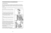
... Leg Press Seat Frame (79). The top weight will need to be moved to slip off the weight stack. 96 11 8 79 78 93 If a cable tends to the next hole in the Leg Press Seat Frame. Remove the 5/16" x 2 3/4" Bolt (11), the two 5/16" Washers (8), the end of the weight... Nuts to be tightened. If any slack is first used on the weight system, can stretch slightly when it . 8 93 If the cables need to be tightened. Remove the cable and re-install it is felt when using the front weight stack, both 5/16" Nylon Jam Nuts (93) from the Leg Press...
... Leg Press Seat Frame (79). The top weight will need to be moved to slip off the weight stack. 96 11 8 79 78 93 If a cable tends to the next hole in the Leg Press Seat Frame. Remove the 5/16" x 2 3/4" Bolt (11), the two 5/16" Washers (8), the end of the weight... Nuts to be tightened. If any slack is first used on the weight system, can stretch slightly when it . 8 93 If the cables need to be tightened. Remove the cable and re-install it is felt when using the front weight stack, both 5/16" Nylon Jam Nuts (93) from the Leg Press...
Uk Manual
Page 32
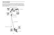
... pages show the proper positioning of the High Cable (58), the Low Cable (23), the Military Press Cable (72), and the Leg Press Cable (78). If the cables have been assembled correctly. High Cable (58) and Low Cable (23) 7 5 23 4 1-High Pulley TOP VIEW 6 High Cable (58) 5-Long "U"-Bracket Low Cable (23) Front Weight Stack-8 4 3 2 1-Low Pulley 25 The...
... pages show the proper positioning of the High Cable (58), the Low Cable (23), the Military Press Cable (72), and the Leg Press Cable (78). If the cables have been assembled correctly. High Cable (58) and Low Cable (23) 7 5 23 4 1-High Pulley TOP VIEW 6 High Cable (58) 5-Long "U"-Bracket Low Cable (23) Front Weight Stack-8 4 3 2 1-Low Pulley 25 The...


