
English Manual
Page 2
WEIDER is a registered trademark of this manual. TABLE OF CONTENTS IMPORTANT PRECAUTIONS 3 BEFORE YOU BEGIN 4 ASSEMBLY 5 ADJUSTMENTS 21 WEIGHT RESISTANCE CHART 23 TROUBLE-SHOOTING AND MAINTENANCE 24 CABLE DIAGRAMS 25 ORDERING REPLACEMENT PARTS Back Cover LIMITED WARRANTY Back Cover Note: A PART IDENTIFICATION CHART and a PART LIST/EXPLODED DRAWING are attached at the center of ICON Health & Fitness, Inc. 2 Remove the PART IDENTIFICATION CHART and the PART LIST/EXPLODED DRAWING before beginning assembly.
WEIDER is a registered trademark of this manual. TABLE OF CONTENTS IMPORTANT PRECAUTIONS 3 BEFORE YOU BEGIN 4 ASSEMBLY 5 ADJUSTMENTS 21 WEIGHT RESISTANCE CHART 23 TROUBLE-SHOOTING AND MAINTENANCE 24 CABLE DIAGRAMS 25 ORDERING REPLACEMENT PARTS Back Cover LIMITED WARRANTY Back Cover Note: A PART IDENTIFICATION CHART and a PART LIST/EXPLODED DRAWING are attached at the center of ICON Health & Fitness, Inc. 2 Remove the PART IDENTIFICATION CHART and the PART LIST/EXPLODED DRAWING before beginning assembly.
English Manual
Page 4
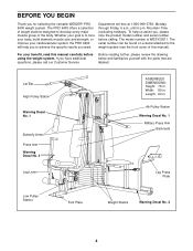
...to tone your body, build dramatic muscle size and strength, or improve your benefit, read this manual). If you for selecting the versatile WEIDER® PRO 9400 weight system. until 6 p.m. The serial number can be found on a decal attached to the weight system (see the front cover of ...Warning Decal No. 1 Butterfly Arms Press Arm Warning Decal No. 3 ASSEMBLED DIMENSIONS: Height: 76 in . Length: 64 in . Department toll-free at 1-800-999-3756, Monday through Friday, 6 a.m. For your cardiovascular system, the PRO 9400 will help us assist you want. To help you to develop every ...
...to tone your body, build dramatic muscle size and strength, or improve your benefit, read this manual). If you for selecting the versatile WEIDER® PRO 9400 weight system. until 6 p.m. The serial number can be found on a decal attached to the weight system (see the front cover of ...Warning Decal No. 1 Butterfly Arms Press Arm Warning Decal No. 3 ASSEMBLED DIMENSIONS: Height: 76 in . Length: 64 in . Department toll-free at 1-800-999-3756, Monday through Friday, 6 a.m. For your cardiovascular system, the PRO 9400 will help us assist you want. To help you to develop every ...
English Manual
Page 5
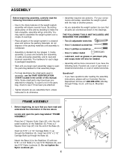
...that you have been preattached for shipping. If a part is not in the box above. Locate and open the parts bag labeled "FRAME ASSEMBLY." Questions? • If you begin each stage is divided into the end of the packing materials until 6 p.m. Press a 2" Square... (1) standard screwdriver • One (1) phillips screwdriver • One (1) rubber mallet • Lubricant, such as shown in the drawings. ASSEMBLY Before beginning assembly, carefully read and understand the information in the parts bag, check to see if it has been pre-attached. • Tighten all parts...
...that you have been preattached for shipping. If a part is not in the box above. Locate and open the parts bag labeled "FRAME ASSEMBLY." Questions? • If you begin each stage is divided into the end of the packing materials until 6 p.m. Press a 2" Square... (1) standard screwdriver • One (1) phillips screwdriver • One (1) rubber mallet • Lubricant, such as shown in the drawings. ASSEMBLY Before beginning assembly, carefully read and understand the information in the parts bag, check to see if it has been pre-attached. • Tighten all parts...
English Manual
Page 9
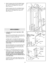
Attach the upper ends of the Stabilizer (5). Locate and open the parts bag labeled "ARM ASSEMBLY." Make sure that the indicated holes are on each side of the Long Weight Guides (62) to the Base (4) with the Bolt and a 3/8" Nylon Locknut (... Plate to the Top Frame (55) with a 5/16" x 6" Bolt (60), two 1/2" x 3/4" Spacers (61), and a 5/16" Nylon Locknut (3). 9 61 60 73 3 61 60 3 55 62 ARM ASSEMBLY 10. Attach the upper ends of the Short Weight Guides (73) to the Leg Press Arm with one set of holes in each end of...
Attach the upper ends of the Stabilizer (5). Locate and open the parts bag labeled "ARM ASSEMBLY." Make sure that the indicated holes are on each side of the Long Weight Guides (62) to the Base (4) with the Bolt and a 3/8" Nylon Locknut (... Plate to the Top Frame (55) with a 5/16" x 6" Bolt (60), two 1/2" x 3/4" Spacers (61), and a 5/16" Nylon Locknut (3). 9 61 60 73 3 61 60 3 55 62 ARM ASSEMBLY 10. Attach the upper ends of the Short Weight Guides (73) to the Leg Press Arm with one set of holes in each end of...

English Manual
Page 10
...) with soapy water. Press 1 3/4" Square Inner Caps (44) into one side of each Arm with two 5/16" x 2 1/2" Bolts (22) and two 5/16" Nylon Locknuts (3). 22 Assemble the other Press Arm (46) in the same manner. Press a 1 3/4" Square Inner Cap (44) into the Press Arm. 44 49 Attach the Press Arm (46...
...) with soapy water. Press 1 3/4" Square Inner Caps (44) into one side of each Arm with two 5/16" x 2 1/2" Bolts (22) and two 5/16" Nylon Locknuts (3). 22 Assemble the other Press Arm (46) in the same manner. Press a 1 3/4" Square Inner Cap (44) into the Press Arm. 44 49 Attach the Press Arm (46...
English Manual
Page 11
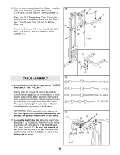
... High Cable (58). See the inset drawing. The approximate length of the Pulley and that the end of the Military Press Arm (84). IMPORTANT: While assembling the cables, do not over tighten the bolts and nuts attaching the 17 pulleys; Press two 1" Round Inner Caps (49) into the indicated end of... Arm (80) to the Pivot Arm (80) with a 3/8" x 3 1/4" Bolt (67) and a 3/8" Nylon Locknut (21). 74 32 49 32 84 80 67 56 33 80 CABLE ASSEMBLY 16 16. 15. Be sure that the Cable is listed (in inches) after the key number in the drawing. Attach the Military Press Arm 15...
... High Cable (58). See the inset drawing. The approximate length of the Pulley and that the end of the Military Press Arm (84). IMPORTANT: While assembling the cables, do not over tighten the bolts and nuts attaching the 17 pulleys; Press two 1" Round Inner Caps (49) into the indicated end of... Arm (80) to the Pivot Arm (80) with a 3/8" x 3 1/4" Bolt (67) and a 3/8" Nylon Locknut (21). 74 32 49 32 84 80 67 56 33 80 CABLE ASSEMBLY 16 16. 15. Be sure that the Cable is listed (in inches) after the key number in the drawing. Attach the Military Press Arm 15...
English Manual
Page 13
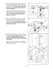
22. See the inset drawing. Note: This may come pre-assembled. Wrap the High Cable (58) around a 3 1/2" Pulley 23 (15). Attach the Pulley to a Small "U"-Bracket 24 (71) with a 3/8" x 2" Bolt (12) and a 3/8" Nylon Locknut (21). Route ...
22. See the inset drawing. Note: This may come pre-assembled. Wrap the High Cable (58) around a 3 1/2" Pulley 23 (15). Attach the Pulley to a Small "U"-Bracket 24 (71) with a 3/8" x 2" Bolt (12) and a 3/8" Nylon Locknut (21). Route ...
English Manual
Page 18
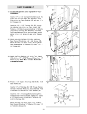
... 10 43 18 37 92 2 38 13 18 79 10 43 39 42 41 43 10 40. Locate and open the parts bag labeled "SEAT ASSEMBLY." Attach the Seat Plate to the Leg Press Seat Frame (79) with a 1/4" Washer (10) and a 1/4" x 2 1/2" Screw (43). 39. Attach the top of a Seat (13) to... Front Seat Frame (36). Attach one end of the Leg Press Backrest (85) to the Seat (13) with a 1/4" x 2 1/2" Screw (43) and a 1/4" Washer (10). 38. SEAT ASSEMBLY 37.
... 10 43 18 37 92 2 38 13 18 79 10 43 39 42 41 43 10 40. Locate and open the parts bag labeled "SEAT ASSEMBLY." Attach the Seat Plate to the Leg Press Seat Frame (79) with a 1/4" Washer (10) and a 1/4" x 2 1/2" Screw (43). 39. Attach the top of a Seat (13) to... Front Seat Frame (36). Attach one end of the Leg Press Backrest (85) to the Seat (13) with a 1/4" x 2 1/2" Screw (43) and a 1/4" Washer (10). 38. SEAT ASSEMBLY 37.
English Manual
Page 25
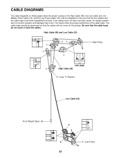
If the cables have been assembled correctly. Be sure that the four cables and the cable traps have not been correctly routed, the weight system will not come off the pulleys. ...
If the cables have been assembled correctly. Be sure that the four cables and the cable traps have not been correctly routed, the weight system will not come off the pulleys. ...


