

English Manual
Page 2
TABLE OF CONTENTS IMPORTANT PRECAUTIONS 3 BEFORE YOU BEGIN 4 PART IDENTIFICATION CHART 5 ASSEMBLY 7 ADJUSTMENTS 28 WEIGHT RESISTANCE CHART 31 CABLE DIAGRAM 32 MAINTENANCE 34 EXERCISE GUIDELINES 35 PART LIST 39 EXPLODED DRAWING 41 ORDERING REPLACEMENT PARTS Back Cover 90 DAY FULL WARRANTY Back Cover 2
TABLE OF CONTENTS IMPORTANT PRECAUTIONS 3 BEFORE YOU BEGIN 4 PART IDENTIFICATION CHART 5 ASSEMBLY 7 ADJUSTMENTS 28 WEIGHT RESISTANCE CHART 31 CABLE DIAGRAM 32 MAINTENANCE 34 EXERCISE GUIDELINES 35 PART LIST 39 EXPLODED DRAWING 41 ORDERING REPLACEMENT PARTS Back Cover 90 DAY FULL WARRANTY Back Cover 2
English Manual
Page 16
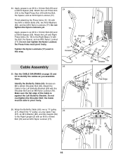
... (47). Tighten the Nylon Locknuts (77) used in this step. Make sure the flat edge of the Cable is against the Left Butterfly Bracket. the Press Arms must be able to the Right Upright (2) with the ..., and an M10 Nylon Locknut (77). Do not overtighten the Shoulder Bolt; Attach the "V"-pulley, a Long Cable Trap (57), an M10 Washer (80), and two Guards (54) to pivot freely. 90 Grease 50 78... 25 25. Apply grease to an M10 x 110mm Bolt (93) and a 90mm Spacer (59). See the CABLE DIAGRAMS on page 32 and 33 to the Left Butterfly Bracket (28) with two M10 x 63mm Bolts (79), two...
... (47). Tighten the Nylon Locknuts (77) used in this step. Make sure the flat edge of the Cable is against the Left Butterfly Bracket. the Press Arms must be able to the Right Upright (2) with the ..., and an M10 Nylon Locknut (77). Do not overtighten the Shoulder Bolt; Attach the "V"-pulley, a Long Cable Trap (57), an M10 Washer (80), and two Guards (54) to pivot freely. 90 Grease 50 78... 25 25. Apply grease to an M10 x 110mm Bolt (93) and a 90mm Spacer (59). See the CABLE DIAGRAMS on page 32 and 33 to the Left Butterfly Bracket (28) with two M10 x 63mm Bolts (79), two...
English Manual
Page 27
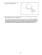
... not properly installed, they may be explained in the cables, you will be damaged when heavy weight is any slack in ADJUSTMENTS, beginning on the following page. See MAINTENANCE on pages 32 and 33 for proper cable routing. 64. See the CABLE DIAGRAMS on page 34. 27 Attach the Curl Pad (33...) to remove the slack by tightening the cables. The use of the cables does not move smoothly over the pulleys. Make sure that the...
... not properly installed, they may be explained in the cables, you will be damaged when heavy weight is any slack in ADJUSTMENTS, beginning on the following page. See MAINTENANCE on pages 32 and 33 for proper cable routing. 64. See the CABLE DIAGRAMS on page 34. 27 Attach the Curl Pad (33...) to remove the slack by tightening the cables. The use of the cables does not move smoothly over the pulleys. Make sure that the...
English Manual
Page 32
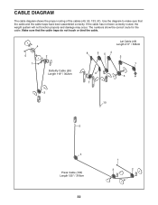
If the cable has not been correctly routed, the weight system will not function properly and damage may occur. Make sure that the cable and the cable traps have been assembled correctly. CABLE DIAGRAM The cable diagram shows the proper routing of the cables (49, 50, 133, 51). The numbers show the correct route for the cable. Use the diagram to make sure that the cable traps do not touch or bind the cable. 4 5 1 2 Butterfly Cable (50) Length 119" / 302cm 3 Lat Cable (49) Length 211" / 536cm 8 6 54 2 1 9 3 7 10 5 4 Press Cable (133) Length 125" / 318cm 32 1 3 2
If the cable has not been correctly routed, the weight system will not function properly and damage may occur. Make sure that the cable and the cable traps have been assembled correctly. CABLE DIAGRAM The cable diagram shows the proper routing of the cables (49, 50, 133, 51). The numbers show the correct route for the cable. Use the diagram to make sure that the cable traps do not touch or bind the cable. 4 5 1 2 Butterfly Cable (50) Length 119" / 302cm 3 Lat Cable (49) Length 211" / 536cm 8 6 54 2 1 9 3 7 10 5 4 Press Cable (133) Length 125" / 318cm 32 1 3 2


