
English Manual
Page 1
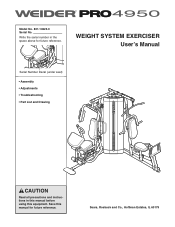
Model No. 831.14623.0 Serial No. Write the serial number in this manual before using this manual for future reference. WEIGHT SYSTEM EXERCISER User's Manual Serial Number Decal (under seat) • Assembly • Adjustments • Troubleshooting • Part List and Drawing CAUTION Read all precautions and instructions in the space above for future reference. Sears, Roebuck and Co., Hoffman Estates, IL 60179 Save this equipment.
Model No. 831.14623.0 Serial No. Write the serial number in this manual before using this manual for future reference. WEIGHT SYSTEM EXERCISER User's Manual Serial Number Decal (under seat) • Assembly • Adjustments • Troubleshooting • Part List and Drawing CAUTION Read all precautions and instructions in the space above for future reference. Sears, Roebuck and Co., Hoffman Estates, IL 60179 Save this equipment.
English Manual
Page 2
TABLE OF CONTENTS IMPORTANT PRECAUTIONS 3 BEFORE YOU BEGIN 4 PART IDENTIFICATION CHART 5 ASSEMBLY 7 ADJUSTMENTS 28 WEIGHT RESISTANCE CHART 31 CABLE DIAGRAM 32 MAINTENANCE 34 EXERCISE GUIDELINES 35 PART LIST 39 EXPLODED DRAWING 41 ORDERING REPLACEMENT PARTS Back Cover 90 DAY FULL WARRANTY Back Cover 2
TABLE OF CONTENTS IMPORTANT PRECAUTIONS 3 BEFORE YOU BEGIN 4 PART IDENTIFICATION CHART 5 ASSEMBLY 7 ADJUSTMENTS 28 WEIGHT RESISTANCE CHART 31 CABLE DIAGRAM 32 MAINTENANCE 34 EXERCISE GUIDELINES 35 PART LIST 39 EXPLODED DRAWING 41 ORDERING REPLACEMENT PARTS Back Cover 90 DAY FULL WARRANTY Back Cover 2
English Manual
Page 3
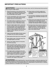
... page 29). 4. If the cable binds as described in the location shown. 5. Do not use the weight system with the lock pin and lock after exercising to increase the resistance. 11. SEARS assumes no responsibility for home use the weight system. 15. If you are exercising, stop immediately and begin cooling down. 14. Keep the weight system indoors, away from moving parts. 7. If the decal is...
... page 29). 4. If the cable binds as described in the location shown. 5. Do not use the weight system with the lock pin and lock after exercising to increase the resistance. 11. SEARS assumes no responsibility for home use the weight system. 15. If you are exercising, stop immediately and begin cooling down. 14. Keep the weight system indoors, away from moving parts. 7. If the decal is...

English Manual
Page 4
... , note the product model number and serial number before using the weight system. Before reading further, please review the drawing below and familiarize yourself with the parts that are determined relative to achieve the specific results you for selecting the versatile WEIDER™ PRO 4950 weight system. For your cardiovascular system, the weight system will help us . Lat Bar Shroud Military Press Arm Backrest Adjustment Knob Weight Leg Press Left Side Seat Seat Adjustment Knob 4 To help...
... , note the product model number and serial number before using the weight system. Before reading further, please review the drawing below and familiarize yourself with the parts that are determined relative to achieve the specific results you for selecting the versatile WEIDER™ PRO 4950 weight system. For your cardiovascular system, the weight system will help us . Lat Bar Shroud Military Press Arm Backrest Adjustment Knob Weight Leg Press Left Side Seat Seat Adjustment Knob 4 To help...
English Manual
Page 5
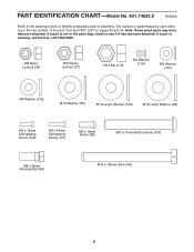
... not in the parts bag, check to identify small parts used in parentheses by each drawing is the key number of the part, from the PART LIST on pages 39 and 40. If a part is missing, call toll-free 1-877-992-5999. The number in assembly. M8 Nylon Locknut (78) M10 Nylon Locknut (77... (105) M12 Large Washer (98) M4 x 12mm Self-tapping Screw (102) M4 x 16mm Self-tapping Screw (110) M6 x 16mm Screw (88) M10 x 75mm Button Screw (118) M8 x 22mm Shoulder Bolt (90) M10 x 100mm Bolt (140) 5 PART IDENTIFICATION CHART-Model No. 831.14623.0 R0606A Refer to the drawings below to see ...
... not in the parts bag, check to identify small parts used in parentheses by each drawing is the key number of the part, from the PART LIST on pages 39 and 40. If a part is missing, call toll-free 1-877-992-5999. The number in assembly. M8 Nylon Locknut (78) M10 Nylon Locknut (77... (105) M12 Large Washer (98) M4 x 12mm Self-tapping Screw (102) M4 x 16mm Self-tapping Screw (110) M6 x 16mm Screw (88) M10 x 75mm Button Screw (118) M8 x 22mm Shoulder Bolt (90) M10 x 100mm Bolt (140) 5 PART IDENTIFICATION CHART-Model No. 831.14623.0 R0606A Refer to the drawings below to see ...
English Manual
Page 7
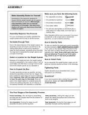
... the small parts used . Seat Assembly-During the final stage you have been pre-attached. Make sure that connect the arms to assemble the weight system over a couple of evenings. ASSEMBLY Make Assembly Easier for the Weight System Because of its weight and size, the weight system should be assembled in the location where it will be used in assembly, we have the following tools: • Two adjustable wrenches •...
... the small parts used . Seat Assembly-During the final stage you have been pre-attached. Make sure that connect the arms to assemble the weight system over a couple of evenings. ASSEMBLY Make Assembly Easier for the Weight System Because of its weight and size, the weight system should be assembled in the location where it will be used in assembly, we have the following tools: • Two adjustable wrenches •...

English Manual
Page 13
.... Press a Bolt Cap (44) onto the end of the Bolt. Arm Assembly 15. Attach the Butterfly Frame (5) to the Right 106 77 Butterfly Arm (26) with two M8 x 80mm Bolts (100), an M10 x 75mm Button Screw (118), two M8 Washers (103), and two M8 Nylon Locknuts (78). Remove the indicated Butterfly Arm Cap (43) from the Right Butterfly Arm (26). Repeat this step. 15...
.... Press a Bolt Cap (44) onto the end of the Bolt. Arm Assembly 15. Attach the Butterfly Frame (5) to the Right 106 77 Butterfly Arm (26) with two M8 x 80mm Bolts (100), an M10 x 75mm Button Screw (118), two M8 Washers (103), and two M8 Nylon Locknuts (78). Remove the indicated Butterfly Arm Cap (43) from the Right Butterfly Arm (26). Repeat this step. 15...

English Manual
Page 15
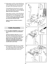
... the indicated hole in the locations shown. See the left inset drawing. Apply grease in the Leg Lever (12). Grease Grease 84 123 124 77 132 22. 21. Apply grease to tw0 M10 x 82mm Bolts (84) 21 and to the indicated locations on the Lock Plate Pin to the Front Leg (10) with the M8 ...sure the barrel of the bracket on the Front Leg. Insert the Lock Plate Pin (95) through both sides of the Bolt Set is oriented as shown in the inset drawing. Attach the Press Arm Handle to the Front Leg (10) with an M4 x 12mm Self-tapping Screw (102). 103 10 14 78 14 102 ...
... the indicated hole in the locations shown. See the left inset drawing. Apply grease in the Leg Lever (12). Grease Grease 84 123 124 77 132 22. 21. Apply grease to tw0 M10 x 82mm Bolts (84) 21 and to the indicated locations on the Lock Plate Pin to the Front Leg (10) with the M8 ...sure the barrel of the bracket on the Front Leg. Insert the Lock Plate Pin (95) through both sides of the Bolt Set is oriented as shown in the inset drawing. Attach the Press Arm Handle to the Front Leg (10) with an M4 x 12mm Self-tapping Screw (102). 103 10 14 78 14 102 ...
English Manual
Page 16
... an M10 Nylon Locknut (77). Grease an M8 x 22mm Shoulder Bolt (90). Wrap the Butterfly Cable (50) over tighten the Nylon Locknut; 24. Attach the Left and Right Press Arms (15, 16) to an M10 x 110mm Bolt (93) and a 90mm Spacer (59). Tighten the Nylon Locknuts (77) used in this step. Finish attaching the Press Arms (15, 16) with the Bolt, the Spacer, and an...
... an M10 Nylon Locknut (77). Grease an M8 x 22mm Shoulder Bolt (90). Wrap the Butterfly Cable (50) over tighten the Nylon Locknut; 24. Attach the Left and Right Press Arms (15, 16) to an M10 x 110mm Bolt (93) and a 90mm Spacer (59). Tighten the Nylon Locknuts (77) used in this step. Finish attaching the Press Arms (15, 16) with the Bolt, the Spacer, and an...
English Manual
Page 24
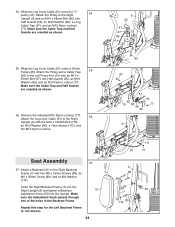
... Leg Lever Cable (51) under a 90mm Pulley (48). Attach the Pulley and a Cable Trap 55 (56) to the Right Upright (2) with an M10 x 50mm Bolt (97), two Half Guards (55), an M10 Washer (80), and an M10 Nylon Locknut (77). Remove the indicated M10 Nylon Locknut (77). 56 Attach the Leg Lever Cable (51) to the Left Press Arm (15) with the M10 x 120mm Bolt...
... Leg Lever Cable (51) under a 90mm Pulley (48). Attach the Pulley and a Cable Trap 55 (56) to the Right Upright (2) with an M10 x 50mm Bolt (97), two Half Guards (55), an M10 Washer (80), and an M10 Nylon Locknut (77). Remove the indicated M10 Nylon Locknut (77). 56 Attach the Leg Lever Cable (51) to the Left Press Arm (15) with the M10 x 120mm Bolt...
English Manual
Page 27
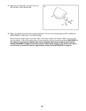
... the problem. Before using the weight system, pull each cable a few times to make sure that all parts have been properly tightened. If there is used. The use of the cables does not move smoothly over the pulleys. See the CABLE DIAGRAMS on page 34. 27 64. Attach the Curl Pad (33) to remove the slack by tightening the cables. IMPORTANT: If the cables are not properly installed, they...
... the problem. Before using the weight system, pull each cable a few times to make sure that all parts have been properly tightened. If there is used. The use of the cables does not move smoothly over the pulleys. See the CABLE DIAGRAMS on page 34. 27 64. Attach the Curl Pad (33) to remove the slack by tightening the cables. IMPORTANT: If the cables are not properly installed, they...
English Manual
Page 28
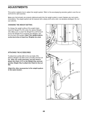
.... ADJUSTMENTS This section explains how to the weight system in the same manner. 49 66 117 66 63 28 Make sure that all parts are used . CHANGING THE WEIGHT SETTING To change the weight setting of the Weight Pin is used . 19 70 ATTACHING THE ACCESSORIES To attach the Lat Bar (63) to the Lat Cable (49), attach a Weight Clip (66) to the Weight Clip, and use solvents. Note: For some exercises, you will need...
.... ADJUSTMENTS This section explains how to the weight system in the same manner. 49 66 117 66 63 28 Make sure that all parts are used . CHANGING THE WEIGHT SETTING To change the weight setting of the Weight Pin is used . 19 70 ATTACHING THE ACCESSORIES To attach the Lat Bar (63) to the Lat Cable (49), attach a Weight Clip (66) to the Weight Clip, and use solvents. Note: For some exercises, you will need...
English Manual
Page 29
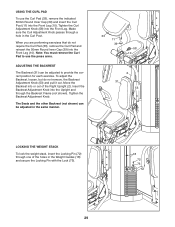
...Pin (72) through a hole in the Weight Guides (18) and secure the Locking Pin with the Lock (73). 18 72 73 29 Tighten the Backrest Adjustment Knob. Tighten the Curl Adjustment Knob (58) into the Upright and through the Backrest Frame (not shown). Insert the Backrest Adjustment Knob into the Front Leg. To adjust the Backrest, loosen, but do not require the Curl Pad (33), remove...the holes in the Curl Post. USING THE CURL PAD To use the press arms. ADJUSTING THE BACKREST The Backrest (31) can be adjusted to use the Curl Pad (33), remove the indicated 50mm Round Inner Cap (...
...Pin (72) through a hole in the Weight Guides (18) and secure the Locking Pin with the Lock (73). 18 72 73 29 Tighten the Backrest Adjustment Knob. Tighten the Curl Adjustment Knob (58) into the Upright and through the Backrest Frame (not shown). Insert the Backrest Adjustment Knob into the Front Leg. To adjust the Backrest, loosen, but do not require the Curl Pad (33), remove...the holes in the Curl Post. USING THE CURL PAD To use the press arms. ADJUSTING THE BACKREST The Backrest (31) can be adjusted to use the Curl Pad (33), remove the indicated 50mm Round Inner Cap (...
English Manual
Page 31
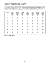
... 338 Note: 1 lb. The maximum number of plates when performing exercises with the Butterfly Arms (25, 26) is for each arm. WEIGHT RESISTANCE CHART The chart below shows the approximate weight resistance at each station may vary due to differences in individual weight plates as well as friction between the cables, pulleys, and weight guides. Weight resistance shown for the butterfly arm station is 10. equals .454 kg...
... 338 Note: 1 lb. The maximum number of plates when performing exercises with the Butterfly Arms (25, 26) is for each arm. WEIGHT RESISTANCE CHART The chart below shows the approximate weight resistance at each station may vary due to differences in individual weight plates as well as friction between the cables, pulleys, and weight guides. Weight resistance shown for the butterfly arm station is 10. equals .454 kg...
English Manual
Page 34
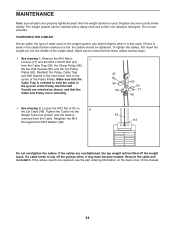
... is used on 2 the Lat Cable (49). If a cable tends to the center of the weight stack. MAINTENANCE Make sure all parts are overtightened, the top weight will be lifted off the pulleys often, it is first used. Do not use solvents. Reattach the Pulley, Cable Trap, and Half Guards to the next closer hole to slip off the weight stack. If the cables are properly tightened...
... is used on 2 the Lat Cable (49). If a cable tends to the center of the weight stack. MAINTENANCE Make sure all parts are overtightened, the top weight will be lifted off the pulleys often, it is first used. Do not use solvents. Reattach the Pulley, Cable Trap, and Half Guards to the next closer hole to slip off the weight stack. If the cables are properly tightened...
English Manual
Page 35
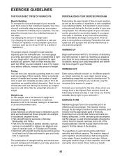
... the time of day when your exercise. Schedule your workouts for each set . This requires moving only the appropriate parts of the body. The repetitions in two ways: • by changing the amount of weight used • by at any exercise program. EXERCISE GUIDELINES THE FOUR BASIC TYPES OF WORKOUTS PERSONALIZING YOUR EXERCISE PROGRAM Muscle Building To increase the size and strength of your muscles, push...
... the time of day when your exercise. Schedule your workouts for each set . This requires moving only the appropriate parts of the body. The repetitions in two ways: • by changing the amount of weight used • by at any exercise program. EXERCISE GUIDELINES THE FOUR BASIC TYPES OF WORKOUTS PERSONALIZING YOUR EXERCISE PROGRAM Muscle Building To increase the size and strength of your muscles, push...
English Manual
Page 36
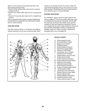
... 30 seconds after each set for a toning work- Ease into each set for each workout. The chart on pages 37, 38 can without strain. Obliques (waist) E. Quadriceps (front of time after each stretch gradually and go only as far as you can be photocopied and used , and the numbers of leg) X. Soleus (front of arm) S. Triceps (back of calf...
... 30 seconds after each set for a toning work- Ease into each set for each workout. The chart on pages 37, 38 can without strain. Obliques (waist) E. Quadriceps (front of time after each stretch gradually and go only as far as you can be photocopied and used , and the numbers of leg) X. Soleus (front of arm) S. Triceps (back of calf...
English Manual
Page 39
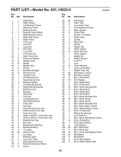
... Cable Trap Long Cable Trap Curl Adjustment Knob 90mm Spacer Pulley Plate Double "U"-bracket Ankle Strap Lat Bar Hand Grip Handle Weight Clip 19mm Spacer 25mm Bushing 57mm Spacer Weight Pin Weight Bumper Lock Pin Lock 16mm Bushing Leg Lever Bumper Weight Tube Cap M10 Nylon Locknut M8 Nylon Locknut M10 x 63mm Bolt M10 Washer M10 x 90mm Bolt M10 x 75mm Bolt M8 x 75mm Carriage Bolt M10 x 82mm Bolt M10 x 68mm Bolt...
... Cable Trap Long Cable Trap Curl Adjustment Knob 90mm Spacer Pulley Plate Double "U"-bracket Ankle Strap Lat Bar Hand Grip Handle Weight Clip 19mm Spacer 25mm Bushing 57mm Spacer Weight Pin Weight Bumper Lock Pin Lock 16mm Bushing Leg Lever Bumper Weight Tube Cap M10 Nylon Locknut M8 Nylon Locknut M10 x 63mm Bolt M10 Washer M10 x 90mm Bolt M10 x 75mm Bolt M8 x 75mm Carriage Bolt M10 x 82mm Bolt M10 x 68mm Bolt...
English Manual
Page 40
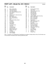
... Cap 44mm Bushing Top Frame Plate 77mm Bushing 40mm x 25mm x 2mm Inner Cap M10 x 100mm Bolt M10 x 141mm Bolt M10 x 40mm Bolt Foam Cover 28mm Round Inner Cap M6 x 45mm Screw Foot Plate Bottom Center Base Top Center Frame Press Arm Handgip 34mm Round Inner Cap "U"-bracket User's Manual Exercise Guide Hex Key Grease Pack Note: "#" indicates a non-illustrated part. PART LIST-Model No. 831.14623.0 R0606A...
... Cap 44mm Bushing Top Frame Plate 77mm Bushing 40mm x 25mm x 2mm Inner Cap M10 x 100mm Bolt M10 x 141mm Bolt M10 x 40mm Bolt Foam Cover 28mm Round Inner Cap M6 x 45mm Screw Foot Plate Bottom Center Base Top Center Frame Press Arm Handgip 34mm Round Inner Cap "U"-bracket User's Manual Exercise Guide Hex Key Grease Pack Note: "#" indicates a non-illustrated part. PART LIST-Model No. 831.14623.0 R0606A...

English Manual
Page 44
... for the location of Sears Brands, LLC ® Marca Registrada / TM Marca de Fábrica / SM Marca de Servicio de Sears Brands, LLC 90 DAY FULL WARRANTY If this Sears WEIGHT SYSTEM EXERCISER fails due to state. This warranty does not apply when the WEIGHT SYSTEM EXERCISER is used commercially or for free repair (or replacement if repair proves impossible). For the replacement parts, accessories, and user's manuals that...
... for the location of Sears Brands, LLC ® Marca Registrada / TM Marca de Fábrica / SM Marca de Servicio de Sears Brands, LLC 90 DAY FULL WARRANTY If this Sears WEIGHT SYSTEM EXERCISER fails due to state. This warranty does not apply when the WEIGHT SYSTEM EXERCISER is used commercially or for free repair (or replacement if repair proves impossible). For the replacement parts, accessories, and user's manuals that...


