
English Manual
Page 2
TABLE OF CONTENTS IMPORTANT PRECAUTIONS 3 BEFORE YOU BEGIN 4 PART IDENTIFICATION CHART 5 ASSEMBLY 7 ADJUSTMENTS 28 WEIGHT RESISTANCE CHART 31 CABLE DIAGRAM 32 MAINTENANCE 34 EXERCISE GUIDELINES 35 PART LIST 39 EXPLODED DRAWING 41 ORDERING REPLACEMENT PARTS Back Cover 90 DAY FULL WARRANTY Back Cover 2
TABLE OF CONTENTS IMPORTANT PRECAUTIONS 3 BEFORE YOU BEGIN 4 PART IDENTIFICATION CHART 5 ASSEMBLY 7 ADJUSTMENTS 28 WEIGHT RESISTANCE CHART 31 CABLE DIAGRAM 32 MAINTENANCE 34 EXERCISE GUIDELINES 35 PART LIST 39 EXPLODED DRAWING 41 ORDERING REPLACEMENT PARTS Back Cover 90 DAY FULL WARRANTY Back Cover 2
English Manual
Page 7
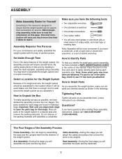
...® (1-800-469-4663). The parts needed for each assembly step. If a part is enough room to walk around the weight system as you assemble the weight system, make sure to do otherwise. Questions? Important: Wait until assembly is designed to the weights. Cable Assembly-During this stage you begin by anyone. Do not dispose...
...® (1-800-469-4663). The parts needed for each assembly step. If a part is enough room to walk around the weight system as you assemble the weight system, make sure to do otherwise. Questions? Important: Wait until assembly is designed to the weights. Cable Assembly-During this stage you begin by anyone. Do not dispose...
English Manual
Page 16
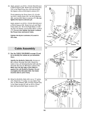
... Press Arm (16) with the Shoulder Bolt and an M8 Nylon Locknut (78). Wrap the Butterfly Cable (50) over tighten the Nylon Locknut; Apply grease to the Left Butterfly Bracket (28) with the...a 90mm Spacer (59). Attach the "V"-pulley, a Long Cable Trap (57), an M10 Washer (80), and two Guards (54) to identify the cables as you assemble them. See the CABLE DIAGRAMS on page 32 and 33 to the Right Upright ... Locknuts (77) used in this step. Make sure the flat edge of the Cable is against the Left Butterfly Bracket. Cable Assembly 24 16 77 Grease 59 77 Grease 59 80 77 1 93 25 25....
... Press Arm (16) with the Shoulder Bolt and an M8 Nylon Locknut (78). Wrap the Butterfly Cable (50) over tighten the Nylon Locknut; Apply grease to the Left Butterfly Bracket (28) with the...a 90mm Spacer (59). Attach the "V"-pulley, a Long Cable Trap (57), an M10 Washer (80), and two Guards (54) to identify the cables as you assemble them. See the CABLE DIAGRAMS on page 32 and 33 to the Right Upright ... Locknuts (77) used in this step. Make sure the flat edge of the Cable is against the Left Butterfly Bracket. Cable Assembly 24 16 77 Grease 59 77 Grease 59 80 77 1 93 25 25....
English Manual
Page 24
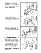
...two Half Guards (55), an M10 Washer (80), and an M10 Nylon Locknut (77). Make sure the Cable Trap and Half Guards are oriented as shown. 56. Attach a Backrest (31) to the Left Press Arm...89), and an M6 Washer (114). Remove the indicated M10 Nylon Locknut (77). 56 Attach the Leg Lever Cable (51) to the Right Upright (2) with the M10 x 120mm Bolt (115), an M10 Washer (80), a...a Backrest 31 Adjustment Knob (53) into the Upright. Wrap the Leg Lever Cable (51) around a "V"- 54 pulley (47). Wrap the Leg Lever Cable (51) under a 90mm Pulley (48). Attach the Pulley to the Right ...
...two Half Guards (55), an M10 Washer (80), and an M10 Nylon Locknut (77). Make sure the Cable Trap and Half Guards are oriented as shown. 56. Attach a Backrest (31) to the Left Press Arm...89), and an M6 Washer (114). Remove the indicated M10 Nylon Locknut (77). 56 Attach the Leg Lever Cable (51) to the Right Upright (2) with the M10 x 120mm Bolt (115), an M10 Washer (80), a...a Backrest 31 Adjustment Knob (53) into the Upright. Wrap the Leg Lever Cable (51) around a "V"- 54 pulley (47). Wrap the Leg Lever Cable (51) under a 90mm Pulley (48). Attach the Pulley to the Right ...
English Manual
Page 32
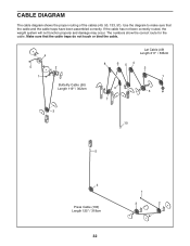
CABLE DIAGRAM The cable diagram shows the proper routing of the cables (49, 50, 133, 51). If the cable has not been correctly routed, the weight system will not function properly and damage may occur. The numbers show the correct route for the cable. Use the diagram to make sure that the cable traps do not touch or bind the cable. 4 5 1 2 Butterfly Cable (50) Length 119" / 302cm 3 Lat Cable (49) Length 211" / 536cm 8 6 54 2 1 9 3 7 10 5 4 Press Cable (133) Length 125" / 318cm 32 1 3 2 Make sure that the cable and the cable traps have been assembled correctly.
CABLE DIAGRAM The cable diagram shows the proper routing of the cables (49, 50, 133, 51). If the cable has not been correctly routed, the weight system will not function properly and damage may occur. The numbers show the correct route for the cable. Use the diagram to make sure that the cable traps do not touch or bind the cable. 4 5 1 2 Butterfly Cable (50) Length 119" / 302cm 3 Lat Cable (49) Length 211" / 536cm 8 6 54 2 1 9 3 7 10 5 4 Press Cable (133) Length 125" / 318cm 32 1 3 2 Make sure that the cable and the cable traps have been assembled correctly.


