
English Manual
Page 1
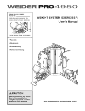
Sears, Roebuck and Co., Hoffman Estates, IL 60179 Save this equipment. WEIGHT SYSTEM EXERCISER User's Manual Serial Number Decal (under seat) • Assembly • Adjustments • Troubleshooting • Part List and Drawing CAUTION Read all precautions and instructions in the space above for future reference. Model No. 831.14623.0 Serial No. Write the serial number in this manual before using this manual for future reference.
Sears, Roebuck and Co., Hoffman Estates, IL 60179 Save this equipment. WEIGHT SYSTEM EXERCISER User's Manual Serial Number Decal (under seat) • Assembly • Adjustments • Troubleshooting • Part List and Drawing CAUTION Read all precautions and instructions in the space above for future reference. Model No. 831.14623.0 Serial No. Write the serial number in this manual before using this manual for future reference.

English Manual
Page 2
TABLE OF CONTENTS IMPORTANT PRECAUTIONS 3 BEFORE YOU BEGIN 4 PART IDENTIFICATION CHART 5 ASSEMBLY 7 ADJUSTMENTS 28 WEIGHT RESISTANCE CHART 31 CABLE DIAGRAM 32 MAINTENANCE 34 EXERCISE GUIDELINES 35 PART LIST 39 EXPLODED DRAWING 41 ORDERING REPLACEMENT PARTS Back Cover 90 DAY FULL WARRANTY Back Cover 2
TABLE OF CONTENTS IMPORTANT PRECAUTIONS 3 BEFORE YOU BEGIN 4 PART IDENTIFICATION CHART 5 ASSEMBLY 7 ADJUSTMENTS 28 WEIGHT RESISTANCE CHART 31 CABLE DIAGRAM 32 MAINTENANCE 34 EXERCISE GUIDELINES 35 PART LIST 39 EXPLODED DRAWING 41 ORDERING REPLACEMENT PARTS Back Cover 90 DAY FULL WARRANTY Back Cover 2

English Manual
Page 4
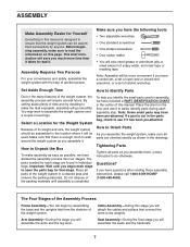
... and familiarize yourself with the parts that are determined relative to right and left side" are labeled. If you for selecting the versatile WEIDER™ PRO 4950 weight system. Lat Bar Shroud Military Press Arm Backrest Adjustment Knob Weight Leg Press Left Side Seat Seat Adjustment Knob 4 BEFORE YOU BEGIN... body. The serial number can be found on the drawings in the manual. they do not correspond to a person facing away from the weight system; ASSEMBLED DIMENSIONS: Height: 82 in. / 208 cm Width: 95 in. / 241 cm Depth: 94 in. / 239 cm Butterfly Arm Right Side Backrest Press...
... and familiarize yourself with the parts that are determined relative to right and left side" are labeled. If you for selecting the versatile WEIDER™ PRO 4950 weight system. Lat Bar Shroud Military Press Arm Backrest Adjustment Knob Weight Leg Press Left Side Seat Seat Adjustment Knob 4 BEFORE YOU BEGIN... body. The serial number can be found on the drawings in the manual. they do not correspond to a person facing away from the weight system; ASSEMBLED DIMENSIONS: Height: 82 in. / 208 cm Width: 95 in. / 241 cm Depth: 94 in. / 239 cm Butterfly Arm Right Side Backrest Press...
English Manual
Page 5
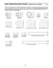
... (90) M10 x 100mm Bolt (140) 5 The number in parentheses by each drawing is not in the parts bag, check to identify small parts used in assembly. If a part is missing, call toll-free 1-877-992-5999. PART IDENTIFICATION CHART-Model No. 831.14623.0 R0606A Refer to the drawings below to see...
... (90) M10 x 100mm Bolt (140) 5 The number in parentheses by each drawing is not in the parts bag, check to identify small parts used in assembly. If a part is missing, call toll-free 1-877-992-5999. PART IDENTIFICATION CHART-Model No. 831.14623.0 R0606A Refer to the drawings below to see...
English Manual
Page 7
...wrenches • One standard screwdriver • One phillips screwdriver • One rubber mallet • You will require several hours. Questions? Arm Assembly-During this manual. Place all parts are found in individual bags. To help of the weight system. Place the chart on this stage you ... weight system in a cleared area and remove the packing materials. How to Orient Parts As you will be assembled successfully by anyone. Before beginning assembly, make assembly as easy as you have been pre-attached. The parts needed for that the weight system can be used...
...wrenches • One standard screwdriver • One phillips screwdriver • One rubber mallet • You will require several hours. Questions? Arm Assembly-During this manual. Place all parts are found in individual bags. To help of the weight system. Place the chart on this stage you ... weight system in a cleared area and remove the packing materials. How to Orient Parts As you will be assembled successfully by anyone. Before beginning assembly, make assembly as easy as you have been pre-attached. The parts needed for that the weight system can be used...
English Manual
Page 8
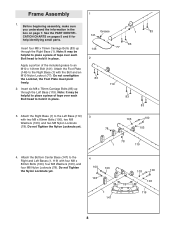
... 3. Do not overtighten the Locknut, the Foot Plate must pivot freely. 2. Insert four M8 x 75mm Carriage Bolts (83) up through the Right Base (1). Before beginning assembly, make sure you understand the information in place. Apply a portion of tape over each Bolt head to hold it in the box on pages 5 and... Base (147) to an M10 x 141mm Bolt (141). Do not Tighten the Nylon Locknuts yet. 4 100 103 103 1 147 103 100 103 78 119 8 Frame Assembly 1 1. See the PART IDENTIFICATION CHARTS on page 7.
... 3. Do not overtighten the Locknut, the Foot Plate must pivot freely. 2. Insert four M8 x 75mm Carriage Bolts (83) up through the Right Base (1). Before beginning assembly, make sure you understand the information in place. Apply a portion of tape over each Bolt head to hold it in the box on pages 5 and... Base (147) to an M10 x 141mm Bolt (141). Do not Tighten the Nylon Locknuts yet. 4 100 103 103 1 147 103 100 103 78 119 8 Frame Assembly 1 1. See the PART IDENTIFICATION CHARTS on page 7.

English Manual
Page 13
Arm Assembly 15. Attach the Butterfly Frame (5) to the Right 106 77 Butterfly Arm (26) with two M8 x 80mm Bolts (100), an M10 x 75mm Button Screw (118), ...
Arm Assembly 15. Attach the Butterfly Frame (5) to the Right 106 77 Butterfly Arm (26) with two M8 x 80mm Bolts (100), an M10 x 75mm Button Screw (118), ...
English Manual
Page 16
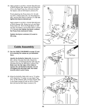
... a "V"-pulley 26 (47). Wrap the Butterfly Cable (50) over tighten the Nylon Locknut; Attach the Left Press Arm (15) to identify the cables as you assemble them. Grease an M8 x 22mm Shoulder Bolt (90). 24. See the CABLE DIAGRAMS on page 32 and 33 to the Right Press Arm (16) with... Right Upright (2) with the Shoulder Bolt and an M8 Nylon Locknut (78). Apply grease to an M10 x 110mm Bolt (93) and a 90mm Spacer (59). Cable Assembly 24 16 77 Grease 59 77 Grease 59 80 77 1 93 25 25. Do not overtighten the Shoulder Bolt; Attach the Left and Right Press...
... a "V"-pulley 26 (47). Wrap the Butterfly Cable (50) over tighten the Nylon Locknut; Attach the Left Press Arm (15) to identify the cables as you assemble them. Grease an M8 x 22mm Shoulder Bolt (90). 24. See the CABLE DIAGRAMS on page 32 and 33 to the Right Press Arm (16) with... Right Upright (2) with the Shoulder Bolt and an M8 Nylon Locknut (78). Apply grease to an M10 x 110mm Bolt (93) and a 90mm Spacer (59). Cable Assembly 24 16 77 Grease 59 77 Grease 59 80 77 1 93 25 25. Do not overtighten the Shoulder Bolt; Attach the Left and Right Press...
English Manual
Page 24
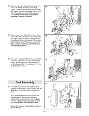
Make sure the Cable Trap and Half Guards are oriented as shown. 56. Wrap the Leg Lever Cable (51) under a 90mm Pulley (48). Seat Assembly 57 57. Remove the indicated M10 Nylon Locknut (77). 56 Attach the Leg Lever Cable (51) to the Right Upright (2) with the M10 x 120mm Bolt (...
Make sure the Cable Trap and Half Guards are oriented as shown. 56. Wrap the Leg Lever Cable (51) under a 90mm Pulley (48). Seat Assembly 57 57. Remove the indicated M10 Nylon Locknut (77). 56 Attach the Leg Lever Cable (51) to the Right Upright (2) with the M10 x 120mm Bolt (...
English Manual
Page 32
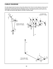
If the cable has not been correctly routed, the weight system will not function properly and damage may occur. Make sure that the cable and the cable traps have been assembled correctly. Use the diagram to make sure that the cable traps do not touch or bind the cable. 4 5 1 2 Butterfly Cable (50) Length 119" / 302cm 3 Lat Cable (49) Length 211" / 536cm 8 6 54 2 1 9 3 7 10 5 4 Press Cable (133) Length 125" / 318cm 32 1 3 2 The numbers show the correct route for the cable. CABLE DIAGRAM The cable diagram shows the proper routing of the cables (49, 50, 133, 51).
If the cable has not been correctly routed, the weight system will not function properly and damage may occur. Make sure that the cable and the cable traps have been assembled correctly. Use the diagram to make sure that the cable traps do not touch or bind the cable. 4 5 1 2 Butterfly Cable (50) Length 119" / 302cm 3 Lat Cable (49) Length 211" / 536cm 8 6 54 2 1 9 3 7 10 5 4 Press Cable (133) Length 125" / 318cm 32 1 3 2 The numbers show the correct route for the cable. CABLE DIAGRAM The cable diagram shows the proper routing of the cables (49, 50, 133, 51).


