
English Manual
Page 2
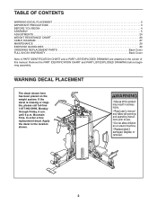
Apply the decal in the center of this manual. Remove the PART IDENTIFICATION CHART and PART LIST/EXPLODED DRAWING before beginning assembly. until 6 p.m. If the decal is missing or illegible, please call toll-free 1-877-992-5999, Monday through Friday, 6 a.m. ...has been placed on the weight system. TABLE OF CONTENTS WARNING DECAL PLACEMENT 2 IMPORTANT PRECAUTIONS 3 BEFORE YOU BEGIN 4 ASSEMBLY 5 ADJUSTMENTS 24 WEIGHT RESISTANCE CHART 26 CABLE DIAGRAM 27 MAINTENANCE 29 EXERCISE GUIDELINES 30 ORDERING REPLACEMENT PARTS Back Cover FULL 90-DAY WARRANTY Back Cover Note: A PART...
Apply the decal in the center of this manual. Remove the PART IDENTIFICATION CHART and PART LIST/EXPLODED DRAWING before beginning assembly. until 6 p.m. If the decal is missing or illegible, please call toll-free 1-877-992-5999, Monday through Friday, 6 a.m. ...has been placed on the weight system. TABLE OF CONTENTS WARNING DECAL PLACEMENT 2 IMPORTANT PRECAUTIONS 3 BEFORE YOU BEGIN 4 ASSEMBLY 5 ADJUSTMENTS 24 WEIGHT RESISTANCE CHART 26 CABLE DIAGRAM 27 MAINTENANCE 29 EXERCISE GUIDELINES 30 ORDERING REPLACEMENT PARTS Back Cover FULL 90-DAY WARRANTY Back Cover Note: A PART...
English Manual
Page 5
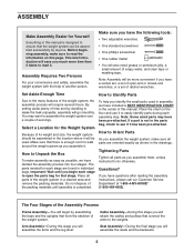
... seats and the backrests. 5 Tightening Parts Tighten all parts as possible, we have divided the assembly process into four stages. Important: Wait until assembly is completed. Cable Assembly-During this stage you will attach the cables and pulleys that the weight system can be more time than it takes to read the information on the...
... seats and the backrests. 5 Tightening Parts Tighten all parts as possible, we have divided the assembly process into four stages. Important: Wait until assembly is completed. Cable Assembly-During this stage you will attach the cables and pulleys that the weight system can be more time than it takes to read the information on the...
English Manual
Page 13
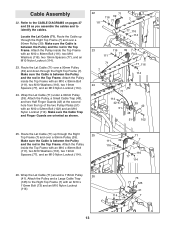
...90mm Pulley (39) and down through the Right Top Frame (7) and over a 90mm Pulley (39). Route the Lat Cable (71) over a 90mm Pulley (39). Wrap the Lat Cable (71) under a 90mm Pulley (39). Cable Assembly 22. Make sure the Cable is between the Pulley and the rod in the Top Frame. Make sure the... Cable Trap and Finger Guards are oriented as you assemble the cables and to the CABLE DIAGRAMS on pages 27 and 28 as ...
...90mm Pulley (39) and down through the Right Top Frame (7) and over a 90mm Pulley (39). Route the Lat Cable (71) over a 90mm Pulley (39). Wrap the Lat Cable (71) under a 90mm Pulley (39). Cable Assembly 22. Make sure the Cable is between the Pulley and the rod in the Top Frame. Make sure the... Cable Trap and Finger Guards are oriented as you assemble the cables and to the CABLE DIAGRAMS on pages 27 and 28 as ...

English Manual
Page 21
... the Upright and Backrest Frame, and turn it clockwise 121 139 until it should be tightened so that only two threads of the Leg Press Cable (69) to the Right 63 Upright (4) with the other Seat (29) and the Left Seat Frame (not shown). 63. Attach the Left Backrest (33) to...) to the 61 "U"-bracket (50) with four M6 x 16mm Screws (85). ing. 117 50 50 69 115 Seat Assembly 62 62. Engage the Knob (121) into the Left Upright (5). 61. Attach the end of the Cable show 115 past the Locknut, as shown in the inset draw- it is tight. 132 21
... the Upright and Backrest Frame, and turn it clockwise 121 139 until it should be tightened so that only two threads of the Leg Press Cable (69) to the Right 63 Upright (4) with the other Seat (29) and the Left Seat Frame (not shown). 63. Attach the Left Backrest (33) to...) to the 61 "U"-bracket (50) with four M6 x 16mm Screws (85). ing. 117 50 50 69 115 Seat Assembly 62 62. Engage the Knob (121) into the Left Upright (5). 61. Attach the end of the Cable show 115 past the Locknut, as shown in the inset draw- it is tight. 132 21
English Manual
Page 27
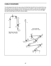
... function properly and damage may occur. Use the diagram to make sure that the cable traps do not touch or bind the cables. 43 1 5 2 6 Right Stack Cable (68) Length: 7 feet 7 inches 9 Press Cable (69) Length: 15 feet 7 inches 6 8 4 7 5 3 2 1 27 If the cables have been assembled correctly. CABLE DIAGRAMS The cable diagrams below show the correct route for each...
... function properly and damage may occur. Use the diagram to make sure that the cable traps do not touch or bind the cables. 43 1 5 2 6 Right Stack Cable (68) Length: 7 feet 7 inches 9 Press Cable (69) Length: 15 feet 7 inches 6 8 4 7 5 3 2 1 27 If the cables have been assembled correctly. CABLE DIAGRAMS The cable diagrams below show the correct route for each...


