

User Manual
Page 1
Serial Number Decal (Under Seat) QUESTIONS? If you . TO AVOID UNNECESSARY DELAYS, PLEASE CALL DIRECT TO OUR TOLL-FREE CUSTOMER HOT LINE. Write the serial number in this manual before using this manual for future reference. Save this equipment. MST CAUTION Read all precautions and instructions in the space above for future reference. CUSTOMER HOT LINE: 1-877-992-5999 Mon.-Fri., 6 a.m.-6 p.m. USER'S MANUAL Visit our website at www.weiderfitness.com new products, prizes, fitness tips, and much more! As a manufacturer, we will provide immediate assistance, free of charge ...
Serial Number Decal (Under Seat) QUESTIONS? If you . TO AVOID UNNECESSARY DELAYS, PLEASE CALL DIRECT TO OUR TOLL-FREE CUSTOMER HOT LINE. Write the serial number in this manual before using this manual for future reference. Save this equipment. MST CAUTION Read all precautions and instructions in the space above for future reference. CUSTOMER HOT LINE: 1-877-992-5999 Mon.-Fri., 6 a.m.-6 p.m. USER'S MANUAL Visit our website at www.weiderfitness.com new products, prizes, fitness tips, and much more! As a manufacturer, we will provide immediate assistance, free of charge ...
User Manual
Page 2
WEIDER is a registered trademark of this manual. Remove the PART IDENTIFICATION CHART and the PART LIST/EXPLODED DRAWING before beginning assembly. TABLE OF CONTENTS IMPORTANT PRECAUTIONS 3 BEFORE YOU BEGIN 4 ASSEMBLY 5 ADJUSTMENTS 22 WEIGHT RESISTANCE CHART 24 MAINTENANCE 25 CABLE DIAGRAMS 26 ORDERING REPLACEMENT PARTS Back Cover LIMITED WARRANTY Back Cover Note: A PART IDENTIFICATION CHART and a PART LIST/EXPLODED DRAWING are attached in the center of ICON IP, Inc. 2
WEIDER is a registered trademark of this manual. Remove the PART IDENTIFICATION CHART and the PART LIST/EXPLODED DRAWING before beginning assembly. TABLE OF CONTENTS IMPORTANT PRECAUTIONS 3 BEFORE YOU BEGIN 4 ASSEMBLY 5 ADJUSTMENTS 22 WEIGHT RESISTANCE CHART 24 MAINTENANCE 25 CABLE DIAGRAMS 26 ORDERING REPLACEMENT PARTS Back Cover LIMITED WARRANTY Back Cover Note: A PART IDENTIFICATION CHART and a PART LIST/EXPLODED DRAWING are attached in the center of ICON IP, Inc. 2
User Manual
Page 3
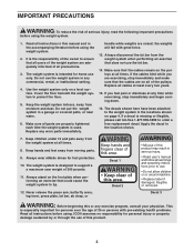
Read all instructions before using. The weight system is designed to the weight system in a garage or covered patio, or near water. 6. Do not use the weight system in the accompanying literature before using the weight system. 1. Do not put the weight system in the locations shown on all times. 8. the weights will fall with pre-existing health problems. Read all instructions in this product. 3 If you are on page 4. The weight system is intended for persons over the age of 35 or persons with great force. 13. Never release the press arm, butterfly arms, leg lever, ...
Read all instructions before using. The weight system is designed to the weight system in a garage or covered patio, or near water. 6. Do not use the weight system in the accompanying literature before using the weight system. 1. Do not put the weight system in the locations shown on all times. 8. the weights will fall with pre-existing health problems. Read all instructions in this product. 3 If you are on page 4. The weight system is intended for persons over the age of 35 or persons with great force. 13. Never release the press arm, butterfly arms, leg lever, ...
User Manual
Page 4
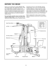
... manual carefully before calling. Width: 64 in . For your goal is WESY26331. To help you to achieve the specific results you for selecting the versatile WEIDER® PRO 3750 weight system. Mountain Time (excluding holidays). Length: 70 in . Butterfly Arms Press Arm Decal1 Leg Lever Leg Press Plate Low Pulley Station Foot Plate...
... manual carefully before calling. Width: 64 in . For your goal is WESY26331. To help you to achieve the specific results you for selecting the versatile WEIDER® PRO 3750 weight system. Mountain Time (excluding holidays). Length: 70 in . Butterfly Arms Press Arm Decal1 Leg Lever Leg Press Plate Low Pulley Station Foot Plate...
User Manual
Page 5
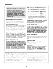
Make sure you have the following tools: • Two (2) adjustable wrenches • One (1) standard screwdriver • One (1) phillips screwdriver • One (1) rubber mallet • You will be assembled successfully by anyone. Note: Assembly will also need grease or petroleum jelly, a small amount of the weight system in a cleared area and remove the packing materials. By setting aside plenty of time and by assembling the base and the uprights that all parts of soapy water, and clear tape or masking tape. How to ensure that stage. Do not dispose of the packing ...
Make sure you have the following tools: • Two (2) adjustable wrenches • One (1) standard screwdriver • One (1) phillips screwdriver • One (1) rubber mallet • You will be assembled successfully by anyone. Note: Assembly will also need grease or petroleum jelly, a small amount of the weight system in a cleared area and remove the packing materials. By setting aside plenty of time and by assembling the base and the uprights that all parts of soapy water, and clear tape or masking tape. How to ensure that stage. Do not dispose of the packing ...
User Manual
Page 6
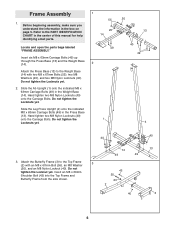
Hand tighten two M8 Nylon Locknuts (40) onto the Carriage Bolts. Do not tighten the Locknut yet. Insert six M8 x 63mm Carriage Bolts (49) up through the Press Base (13) and the Weight Base (14). 2 Attach the Press Base (13) to the Weight Base (14) with an M8 x 67mm Bolt (55), an M8 Washer (20), and an M8 Nylon Locknut (40). Insert an M8 x 69mm Shoulder Bolt (43) into the Top Frame and Butterfly Frame from the side shown. 14 49 49 43 55 20 2 40 40 13 3 6 Do not tighten the Locknuts yet. 2. Before beginning assembly, make sure you understand the information in the ...
Hand tighten two M8 Nylon Locknuts (40) onto the Carriage Bolts. Do not tighten the Locknut yet. Insert six M8 x 63mm Carriage Bolts (49) up through the Press Base (13) and the Weight Base (14). 2 Attach the Press Base (13) to the Weight Base (14) with an M8 x 67mm Bolt (55), an M8 Washer (20), and an M8 Nylon Locknut (40). Insert an M8 x 69mm Shoulder Bolt (43) into the Top Frame and Butterfly Frame from the side shown. 14 49 49 43 55 20 2 40 40 13 3 6 Do not tighten the Locknuts yet. 2. Before beginning assembly, make sure you understand the information in the ...
User Manual
Page 7
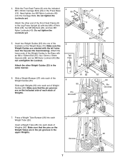
Do Hole 23 not overtighten the Locknut. Slide eight Weights (90) onto each stack of Weights (90). Attach the other Weight Guides (23) in the 40 same manner. 6. Make sure that the pins on the Weight Tubes are in the pin grooves in the Press Base (13). Insert two Weight Guides (23) into each Weight Tube (25). Attach the lower ends of the 5 brackets on the indicated side of each of Weight Guides (23). Press a Weight Tube Bumper (26) into one of the Weight Guides to the Leg Press Upright (4) with two M8 x 67mm Bolts (55), two M8 Washers (20), and two M8 Nylon ...
Do Hole 23 not overtighten the Locknut. Slide eight Weights (90) onto each stack of Weights (90). Attach the other Weight Guides (23) in the 40 same manner. 6. Make sure that the pins on the Weight Tubes are in the pin grooves in the Press Base (13). Insert two Weight Guides (23) into each Weight Tube (25). Attach the lower ends of the 5 brackets on the indicated side of each of Weight Guides (23). Press a Weight Tube Bumper (26) into one of the Weight Guides to the Leg Press Upright (4) with two M8 x 67mm Bolts (55), two M8 Washers (20), and two M8 Nylon ...
User Manual
Page 8
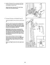
Do not tighten the Locknuts yet. 55 20 55 Attach the Butterfly Frame (3) to the Top Frame (2) in the same manner. Tighten the M8 Nylon Locknuts (40) used in the 8 Top Weights (24) with an M8 x 152mm Bolt (67), two 13mm x 19mm Spacers (69), and an M8 Nylon Locknut (40). Lubricate 23 24 Lubricate 23 9. Attach the upper ends of one set of Weight Guides (23) to the Ab Upright (1) 9 with two M8 x 67mm Bolts (55), two 20 3 M8 Washers (20), and two M8 Nylon Locknuts 2 (40). Attach the upper ends of the other set of Weight Guides (23) to the Leg Press Upright ...
Do not tighten the Locknuts yet. 55 20 55 Attach the Butterfly Frame (3) to the Top Frame (2) in the same manner. Tighten the M8 Nylon Locknuts (40) used in the 8 Top Weights (24) with an M8 x 152mm Bolt (67), two 13mm x 19mm Spacers (69), and an M8 Nylon Locknut (40). Lubricate 23 24 Lubricate 23 9. Attach the upper ends of one set of Weight Guides (23) to the Ab Upright (1) 9 with two M8 x 67mm Bolts (55), two 20 3 M8 Washers (20), and two M8 Nylon Locknuts 2 (40). Attach the upper ends of the other set of Weight Guides (23) to the Leg Press Upright ...
User Manual
Page 9
Attach the Leg Press Plate (11) to the Front 13 Seat Frame (8) with an M8 x 60mm Bolt (62), two M8 Washers (20), and an M8 Nylon Locknut (40). Attach the Leg Press Bumper (53) to the Adjustment Tube (10) with the M5 x 25mm Tap Screw (72). the Leg Press Arm must be able to the Leg Press Arm (9) with the Bolt and an M10 Nylon Locknut (42). Press a 25mm x 22mm Plastic Bushing (54) onto each welded spacer on the side shown. Make sure that the high hole is on the Press Frame (12). Make sure that the Plastic Bushings are oriented as shown. 10 20 40 62 Obtuse 11 Angle 12. ...
Attach the Leg Press Plate (11) to the Front 13 Seat Frame (8) with an M8 x 60mm Bolt (62), two M8 Washers (20), and an M8 Nylon Locknut (40). Attach the Leg Press Bumper (53) to the Adjustment Tube (10) with the M5 x 25mm Tap Screw (72). the Leg Press Arm must be able to the Leg Press Arm (9) with the Bolt and an M10 Nylon Locknut (42). Press a 25mm x 22mm Plastic Bushing (54) onto each welded spacer on the side shown. Make sure that the high hole is on the Press Frame (12). Make sure that the Plastic Bushings are oriented as shown. 10 20 40 62 Obtuse 11 Angle 12. ...
User Manual
Page 10
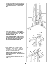
Lubricate both axles on the Butterfly Frame (3). Make sure that the teeth on the Retainers bend toward the Round Outer Cap, as shown in the inset drawing. The Retainers can be removed, you thoroughly understand the step. Make sure that the upper end of the Press 15 Frame (12) with the Right Fly Arm (5). Note: Do not to one side of the Left Fly Arm is behind the indicated bracket on the Butterfly Frame (3). 16 Identify the Right Fly Arm (5) and the Left Fly Arm (6). If they must be assembled only once. Slide the Left Fly Arm (6) onto the indicated axle. Tap two 25mm...
Lubricate both axles on the Butterfly Frame (3). Make sure that the teeth on the Retainers bend toward the Round Outer Cap, as shown in the inset drawing. The Retainers can be removed, you thoroughly understand the step. Make sure that the upper end of the Press 15 Frame (12) with the Right Fly Arm (5). Note: Do not to one side of the Left Fly Arm is behind the indicated bracket on the Butterfly Frame (3). 16 Identify the Right Fly Arm (5) and the Left Fly Arm (6). If they must be assembled only once. Slide the Left Fly Arm (6) onto the indicated axle. Tap two 25mm...
User Manual
Page 11
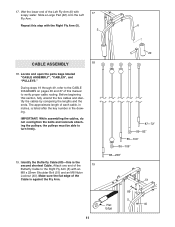
17. the pulleys must be able to the Right Fly Arm (5) with 17 soapy water. Make sure the flat edge of each cable, in inches, is listed after the key number in the drawing. Before beginning this step with the Right Fly Arm (5). 6 5 CABLE ASSEMBLY 18 18. The approximate length of the Cable is the second shortest Cable. Identify the Butterfly Cable (89)-this manual to verify proper cable routing. Locate and open the parts bags labeled "CABLE ASSEMBLY", "CABLES", and "PULLEYS." IMPORTANT: While assembling the cables, do not overtighten the bolts and locknuts attaching ...
17. the pulleys must be able to the Right Fly Arm (5) with 17 soapy water. Make sure the flat edge of each cable, in inches, is listed after the key number in the drawing. Before beginning this step with the Right Fly Arm (5). 6 5 CABLE ASSEMBLY 18 18. The approximate length of the Cable is the second shortest Cable. Identify the Butterfly Cable (89)-this manual to verify proper cable routing. Locate and open the parts bags labeled "CABLE ASSEMBLY", "CABLES", and "PULLEYS." IMPORTANT: While assembling the cables, do not overtighten the bolts and locknuts attaching ...
User Manual
Page 12
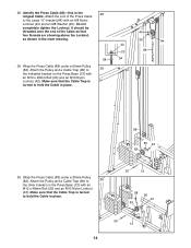
Wrap the Butterfly Cable (89) around a 90mm 20 Pulley (82) as shown. Attach the Pulley and a Cable Trap 21 (80) between the single hole ends of the bracket on the Leg Press Upright (4) with an M8 x 22mm Shoulder Bolt (51) and an M8 Nylon Locknut (40). Attach the Pulley and a Cable 22 Trap (80) to the other side of two Pulley Plates (31) with an M10 x 48mm Bolt (50) and an M10 Nylon Locknut (42). Attach the Pulley and a Cable Trap (80) to the Left Fly Arm (6) with an M10 x 48mm Bolt (50) and an M10 Nylon Locknut (42). Wrap the Butterfly Cable (89) under a 90mm Pulley (82)....
Wrap the Butterfly Cable (89) around a 90mm 20 Pulley (82) as shown. Attach the Pulley and a Cable Trap 21 (80) between the single hole ends of the bracket on the Leg Press Upright (4) with an M8 x 22mm Shoulder Bolt (51) and an M8 Nylon Locknut (40). Attach the Pulley and a Cable 22 Trap (80) to the other side of two Pulley Plates (31) with an M10 x 48mm Bolt (50) and an M10 Nylon Locknut (42). Attach the Pulley and a Cable Trap (80) to the Left Fly Arm (6) with an M10 x 48mm Bolt (50) and an M10 Nylon Locknut (42). Wrap the Butterfly Cable (89) under a 90mm Pulley (82)....
User Manual
Page 13
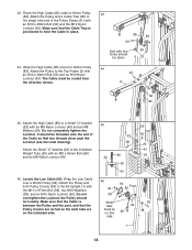
Attach the Rear Cable to the Top Frame with 26 an M10 x 48mm Bolt (50) and an M10 Nylon Locknut (42). See the inset drawing. Flat Edge 25 87 80 82 42 50 84 26. it should be routed from the Top Frame (2). Attach the Pulley to the upper hole in the groove of the Cable is the short- 24 est Cable. Remove the M8 x 69mm Shoulder Bolt (43) from the direction shown. 2 42 40 50 82 87 27. Attach the Pulley and a Cable Trap (80) to the Top Frame (2) with the M8 x 69mm Shoulder Bolt (43) and an M8 Nylon Locknut (40). Wrap the Rear Cable (87) around a 90mm Pulley...
Attach the Rear Cable to the Top Frame with 26 an M10 x 48mm Bolt (50) and an M10 Nylon Locknut (42). See the inset drawing. Flat Edge 25 87 80 82 42 50 84 26. it should be routed from the Top Frame (2). Attach the Pulley to the upper hole in the groove of the Cable is the short- 24 est Cable. Remove the M8 x 69mm Shoulder Bolt (43) from the direction shown. 2 42 40 50 82 87 27. Attach the Pulley and a Cable Trap (80) to the Top Frame (2) with the M8 x 69mm Shoulder Bolt (43) and an M8 Nylon Locknut (40). Wrap the Rear Cable (87) around a 90mm Pulley...
User Manual
Page 14
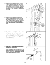
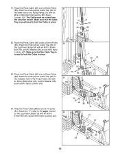
Wrap the Press Cable (88) under a 90mm Pulley (82). Wrap the Press Cable (88) under a 90mm Pulley (82). It should be threaded onto the end of the Press Cable to the Large "U"-bracket (84) with an M8 Nylon Locknut (40) and an M8 Washer (20). Attach the Pulley and a Cable Trap (80) to 29 the indicated bracket on the Press Base (13) with an M10 x 48mm Bolt (50) and an M10 Nylon Locknut (42). Do not completely tighten the Locknut. Make sure that the Cable Trap is turned to hold the Cable in place. 88 80 42 82 30. Make sure that two threads are showing above the...
Wrap the Press Cable (88) under a 90mm Pulley (82). Wrap the Press Cable (88) under a 90mm Pulley (82). It should be threaded onto the end of the Press Cable to the Large "U"-bracket (84) with an M8 Nylon Locknut (40) and an M8 Washer (20). Attach the Pulley and a Cable Trap (80) to 29 the indicated bracket on the Press Base (13) with an M10 x 48mm Bolt (50) and an M10 Nylon Locknut (42). Do not completely tighten the Locknut. Make sure that the Cable Trap is turned to hold the Cable in place. 88 80 42 82 30. Make sure that two threads are showing above the...
User Manual
Page 15
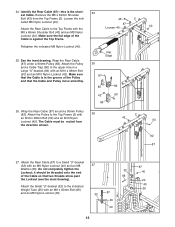
Attach the Pulley and a Cable Trap (80) to the indicated hole in the Pulley Plates (31) with an M10 x 57mm Bolt (91) and an M10 Nylon Locknut (42). 66 38 88 82 80 12 91 81 4 88 42 15 Attach the Pulley and a Cable Trap (80) to the Leg Press Upright (4) with an M10 x 82mm Bolt (66), an M10 Washer (38), and the M10 Nylon Locknut (42). 88 82 76 80 33 4 38 42 42 34. Route the Press Cable (88) over a 90mm Pulley (82). Attach the Pulley and a Cable Trap (80) to the upper bracket 34 on the Leg Press Upright (4) with an M10 x 48mm Bolt (50) and the M10 Nylon Locknut (42)....
Attach the Pulley and a Cable Trap (80) to the indicated hole in the Pulley Plates (31) with an M10 x 57mm Bolt (91) and an M10 Nylon Locknut (42). 66 38 88 82 80 12 91 81 4 88 42 15 Attach the Pulley and a Cable Trap (80) to the Leg Press Upright (4) with an M10 x 82mm Bolt (66), an M10 Washer (38), and the M10 Nylon Locknut (42). 88 82 76 80 33 4 38 42 42 34. Route the Press Cable (88) over a 90mm Pulley (82). Attach the Pulley and a Cable Trap (80) to the upper bracket 34 on the Leg Press Upright (4) with an M10 x 48mm Bolt (50) and the M10 Nylon Locknut (42)....
User Manual
Page 16
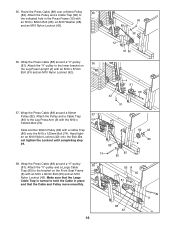
Route the Press Cable (88) over a 90mm Pulley 35 (82). Do not tighten the Locknut until completing step 39. 38. Wrap the Press Cable (88) around a 90mm Pulley (82). Attach the "V"-pulley to the Leg Press Arm (9) with the M10 x 120mm Bolt (74). Hand tighten an M10 Nylon Locknut (42) onto the Bolt. Slide another 90mm Pulley (82) with an M10 x 82mm Bolt (66), an M10 Washer (38), and an M10 Nylon Locknut (42). 66 88 38 12 82 42 80 36. Attach the Pulley and a Cable Trap (80) to the indicated hole in place and that the Large Cable Trap is turned to the bracket on the Leg ...
Route the Press Cable (88) over a 90mm Pulley 35 (82). Do not tighten the Locknut until completing step 39. 38. Wrap the Press Cable (88) around a 90mm Pulley (82). Attach the "V"-pulley to the Leg Press Arm (9) with the M10 x 120mm Bolt (74). Hand tighten an M10 Nylon Locknut (42) onto the Bolt. Slide another 90mm Pulley (82) with an M10 x 82mm Bolt (66), an M10 Washer (38), and an M10 Nylon Locknut (42). 66 88 38 12 82 42 80 36. Attach the Pulley and a Cable Trap (80) to the indicated hole in place and that the Large Cable Trap is turned to the bracket on the Leg ...
User Manual
Page 17
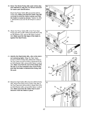
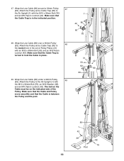
It is the shortest remaining cable. Attach the Press Cable (88) to the Top Frame (2) with an M8 x 69mm Shoulder Bolt (43), 40 an M8 Washer (20), and an M8 Nylon Locknut (40). Attach the Pulley to the Front Seat Frame (8) with an M10 x 92mm Bolt (76), an M10 Washer (38), and an M10 Nylon Locknut (42). Identify the High Cable (85)-this step 39 was attached in place. 76 38 2 80 82 42 85 17 Wrap the High Cable (85) around a 90mm Pulley (82). Wrap the High Cable around a 90mm Pulley 42 (82). Note: The 90mm Pulley (82) used in this is shown removed for ...
It is the shortest remaining cable. Attach the Press Cable (88) to the Top Frame (2) with an M8 x 69mm Shoulder Bolt (43), 40 an M8 Washer (20), and an M8 Nylon Locknut (40). Attach the Pulley to the Front Seat Frame (8) with an M10 x 92mm Bolt (76), an M10 Washer (38), and an M10 Nylon Locknut (42). Identify the High Cable (85)-this step 39 was attached in place. 76 38 2 80 82 42 85 17 Wrap the High Cable (85) around a 90mm Pulley (82). Wrap the High Cable around a 90mm Pulley 42 (82). Note: The 90mm Pulley (82) used in this is shown removed for ...
User Manual
Page 18
43. The Cable must be on the indicated side. 45 32 32 68 85 20 40 85 40 20 40 25 46 42 38 94 82 Post Wide tabs must be routed from the direction shown. 43 85 82 50 End with an M8 Nylon Locknut (40) and an M8 Washer (20). Do not overtighten the Locknut; Attach the High Cable (85) to the indicated Weight Tube (25) with the M10 x 97mm Bolt (95), two M10 Washers (38), and an M10 Nylon Locknut (42). Attach the Small "U"-bracket (32) to a Small "U"-bracket (32) with two 80 holes should be threaded onto the end of the Pulley Plates (31) with an M10 x 48mm Bolt (...
43. The Cable must be on the indicated side. 45 32 32 68 85 20 40 85 40 20 40 25 46 42 38 94 82 Post Wide tabs must be routed from the direction shown. 43 85 82 50 End with an M8 Nylon Locknut (40) and an M8 Washer (20). Do not overtighten the Locknut; Attach the High Cable (85) to the indicated Weight Tube (25) with the M10 x 97mm Bolt (95), two M10 Washers (38), and an M10 Nylon Locknut (42). Attach the Small "U"-bracket (32) to a Small "U"-bracket (32) with two 80 holes should be threaded onto the end of the Pulley Plates (31) with an M10 x 48mm Bolt (...
User Manual
Page 19
Attach the Pulley and a Cable Trap (80) to hold the Cable in the indicated position. 48. Attach the Pulley and a Cable Trap (80) to the Ab Upright (1) with the M10 x 92mm Bolt (76), an M10 Washer (38), and an M10 Nylon Locknut (42). Make sure that the Cable Trap is turned to 48 the lowest hole in the set of the Pulley. Wrap the Low Cable (86) under a 90mm Pulley 49 (82). Wrap the Low Cable (86) around a 90mm Pulley 47 (82). Make sure that the Cable and Pulley move smoothly and that the Cable Trap is between the Pulley and the post. 1 42 86 80 82 76 31 42 50 82 ...
Attach the Pulley and a Cable Trap (80) to hold the Cable in the indicated position. 48. Attach the Pulley and a Cable Trap (80) to the Ab Upright (1) with the M10 x 92mm Bolt (76), an M10 Washer (38), and an M10 Nylon Locknut (42). Make sure that the Cable Trap is turned to 48 the lowest hole in the set of the Pulley. Wrap the Low Cable (86) under a 90mm Pulley 49 (82). Wrap the Low Cable (86) around a 90mm Pulley 47 (82). Make sure that the Cable and Pulley move smoothly and that the Cable Trap is between the Pulley and the post. 1 42 86 80 82 76 31 42 50 82 ...
User Manual
Page 20
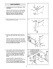
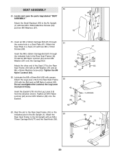
Locate and open the parts bag labeled "SEAT ASSEMBLY." Insert an M6 x 52mm Carriage Bolt (61) through the indicated hole in a Seat Plate (41). Attach the Seat Plate to a Seat (17) with an M6 Washer (37) and an M6 x 52mm Machine Screw (63). Attach the other end of the Seat (17) to the Rear Seat Frame (16) with two M6 x 63mm Machine Screws (64) and two M6 Washers (37). 18 1 37 64 51. Insert the Eyebolt (79) into the Leg Lever (15) from the direction shown. SEAT ASSEMBLY 50 50. Tighten an M10 Nylon Locknut (42) and an M10 Washer (38) onto the Eyebolt. 51 17 61 41 59 16 ...
Locate and open the parts bag labeled "SEAT ASSEMBLY." Insert an M6 x 52mm Carriage Bolt (61) through the indicated hole in a Seat Plate (41). Attach the Seat Plate to a Seat (17) with an M6 Washer (37) and an M6 x 52mm Machine Screw (63). Attach the other end of the Seat (17) to the Rear Seat Frame (16) with two M6 x 63mm Machine Screws (64) and two M6 Washers (37). 18 1 37 64 51. Insert the Eyebolt (79) into the Leg Lever (15) from the direction shown. SEAT ASSEMBLY 50 50. Tighten an M10 Nylon Locknut (42) and an M10 Washer (38) onto the Eyebolt. 51 17 61 41 59 16 ...