

English Manual
Page 2
WEIDER is a registered trademark of this manual. TABLE OF CONTENTS IMPORTANT PRECAUTIONS 3 BEFORE YOU BEGIN 4 ASSEMBLY 5 ADJUSTMENTS 22 WEIGHT RESISTANCE CHART 24 TROUBLESHOOTING 25 CABLE DIAGRAMS 26 ORDERING REPLACEMENT PARTS Back Cover LIMITED WARRANTY Back Cover Note: A PART IDENTIFICATION CHART and a PART LIST/EXPLODED DRAWING are attached in the center of ICON Health & Fitness, Inc. 2 Remove the PART IDENTIFICATION CHART and the PART LIST/EXPLODED DRAWING before beginning assembly.
WEIDER is a registered trademark of this manual. TABLE OF CONTENTS IMPORTANT PRECAUTIONS 3 BEFORE YOU BEGIN 4 ASSEMBLY 5 ADJUSTMENTS 22 WEIGHT RESISTANCE CHART 24 TROUBLESHOOTING 25 CABLE DIAGRAMS 26 ORDERING REPLACEMENT PARTS Back Cover LIMITED WARRANTY Back Cover Note: A PART IDENTIFICATION CHART and a PART LIST/EXPLODED DRAWING are attached in the center of ICON Health & Fitness, Inc. 2 Remove the PART IDENTIFICATION CHART and the PART LIST/EXPLODED DRAWING before beginning assembly.
English Manual
Page 3
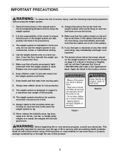
... with great force. Keep hands and fingers clear of this or any commercial, rental, or institutional setting. 4. The weight system should not be used . Use the weight system only on page 4. If a decal is intended for personal injury or property damage sustained by more than one person...bar. 2. Always disconnect the lat bar from moving parts. 8. This is the responsibility of the owner to ensure that all users of the weight system are on the foot plate when performing an exercise that does not use only. It is especially important for foot protection. 9. Decal 2...
... with great force. Keep hands and fingers clear of this or any commercial, rental, or institutional setting. 4. The weight system should not be used . Use the weight system only on page 4. If a decal is intended for personal injury or property damage sustained by more than one person...bar. 2. Always disconnect the lat bar from moving parts. 8. This is the responsibility of the owner to ensure that all users of the weight system are on the foot plate when performing an exercise that does not use only. It is especially important for foot protection. 9. Decal 2...
English Manual
Page 4
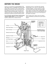
...-3756, Monday through Friday, 6 a.m. The serial number can be found on each side) Weight Stack Squat Arm Backrest Adjustment Knob WARNING DECAL 2 Squat Knee Rest 4 For your cardiovascular system, the PRO 3650 weight system will help us assist you for the location of the body. until 6 p.m. Width:...labeled. The model number is to develop every major muscle group of the decal). If you want. The WEIDER® PRO 3650 weight system offers an impressive array of weight stations designed to tone your body, build dramatic muscle size and strength, or improve your benefit, read ...
...-3756, Monday through Friday, 6 a.m. The serial number can be found on each side) Weight Stack Squat Arm Backrest Adjustment Knob WARNING DECAL 2 Squat Knee Rest 4 For your cardiovascular system, the PRO 3650 weight system will help us assist you for the location of the body. until 6 p.m. Width:...labeled. The model number is to develop every major muscle group of the decal). If you want. The WEIDER® PRO 3650 weight system offers an impressive array of weight stations designed to tone your body, build dramatic muscle size and strength, or improve your benefit, read ...
English Manual
Page 5
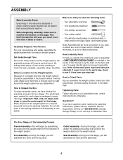
... • One phillips screwdriver • One rubber mallet • You will also need grease or petroleum jelly, a small amount of the weight system. Lay the chart on this stage, you have questions after reading the assembly instructions, please call our Customer Service Department toll-free at ...CHART is packaged in the center of the packing materials until 6 p.m. Note: Assembly will attach the cables and pulleys that connect the weight stations to ensure that there is enough room to Unpack the Box To make the task enjoyable, assembly will require several hours. until assembly...
... • One phillips screwdriver • One rubber mallet • You will also need grease or petroleum jelly, a small amount of the weight system. Lay the chart on this stage, you have questions after reading the assembly instructions, please call our Customer Service Department toll-free at ...CHART is packaged in the center of the packing materials until 6 p.m. Note: Assembly will attach the cables and pulleys that connect the weight stations to ensure that there is enough room to Unpack the Box To make the task enjoyable, assembly will require several hours. until assembly...
English Manual
Page 6
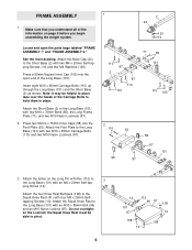
... Inner Caps (58) into the open the parts bags labeled "FRAME ASSEMBLY 1" and "FRAME ASSEMBLY 2." Attach the tether on page 5 before you begin assembling the weight system. 2 24 120 14 Locate and open end of the information on the Long Pin w/Tether (112) to the Long Base (101) with an M4...
... Inner Caps (58) into the open the parts bags labeled "FRAME ASSEMBLY 1" and "FRAME ASSEMBLY 2." Attach the tether on page 5 before you begin assembling the weight system. 2 24 120 14 Locate and open end of the information on the Long Pin w/Tether (112) to the Long Base (101) with an M4...
English Manual
Page 9
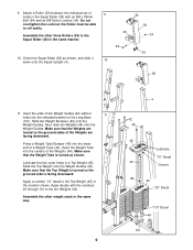
... (34). Slide two Weight Bumpers (49) onto the Weight Guides. Next, slide ten Weights (44) onto the Weight Guides. Insert the Weight Tube into the indicated bracket on the Long Base (101). Make sure that the Weights are turned so the grooved sides of the Weights (44). Press a Weight Tube Bumper (48) ...(38) with the numbers 20 through 110 to the Top Weight (45) in a Top Weight (45). Make sure that the Weight Tube is facing downward. 9. Attach a Roller (39) between the indicated set of a Weight Tube (43). Assemble the other weight stack in the same manner. 39 38 39 34 94 ...
... (34). Slide two Weight Bumpers (49) onto the Weight Guides. Next, slide ten Weights (44) onto the Weight Guides. Insert the Weight Tube into the indicated bracket on the Long Base (101). Make sure that the Weights are turned so the grooved sides of the Weights (44). Press a Weight Tube Bumper (48) ...(38) with the numbers 20 through 110 to the Top Weight (45) in a Top Weight (45). Make sure that the Weight Tube is facing downward. 9. Attach a Roller (39) between the indicated set of a Weight Tube (43). Assemble the other weight stack in the same manner. 39 38 39 34 94 ...
English Manual
Page 10
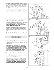
Attach the four Weight Guides (42) to pivot easily. 15. ARM ASSEMBLY 14. the Leg Lever must be able to the Top Frame (6) with two M10 x 70mm Bolts (85), ...
Attach the four Weight Guides (42) to pivot easily. 15. ARM ASSEMBLY 14. the Leg Lever must be able to the Top Frame (6) with two M10 x 70mm Bolts (85), ...
English Manual
Page 12
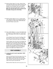
... the Swivel Upright (5). Wrap the Swivel High Cable (74) over a 90mm Pulley (78). Lift the Weight Tube (43) and the Top Weight (45) 22 closest to the Swivel Upright (5). 5 91 87 91 87 89 91 18 18 91 ...89 74 119 20. Insert a Weight Pin (50) into the Weight Tube. Make sure the Cable Trap is turned to the second set of the indicat- Locate the...Tighten an M12 Nut (118) halfway onto the end of the Pulley. 21. Place a 50mm Washer (1) on the Weight Tube is 2930mm 23 long and has an eyelet on the Top Frame (6) with an M10 x 65mm Bolt (18), ...
... the Swivel Upright (5). Wrap the Swivel High Cable (74) over a 90mm Pulley (78). Lift the Weight Tube (43) and the Top Weight (45) 22 closest to the Swivel Upright (5). 5 91 87 91 87 89 91 18 18 91 ...89 74 119 20. Insert a Weight Pin (50) into the Weight Tube. Make sure the Cable Trap is turned to the second set of the indicat- Locate the...Tighten an M12 Nut (118) halfway onto the end of the Pulley. 21. Place a 50mm Washer (1) on the Weight Tube is 2930mm 23 long and has an eyelet on the Top Frame (6) with an M10 x 65mm Bolt (18), ...
English Manual
Page 17
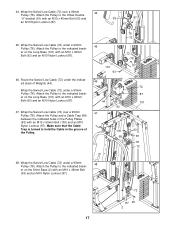
... Swivel Low Cable (72) over a 90mm 44 Pulley (78). 44. Attach the Pulley and a Cable Trap (68) between the indicated holes in the groove of Weights (44). Make sure that the Cable Trap is turned to the indicated brack- Attach the Pulley to hold the Cable in the Pulley Plates (63...
... Swivel Low Cable (72) over a 90mm 44 Pulley (78). 44. Attach the Pulley and a Cable Trap (68) between the indicated holes in the groove of Weights (44). Make sure that the Cable Trap is turned to the indicated brack- Attach the Pulley to hold the Cable in the Pulley Plates (63...
English Manual
Page 19
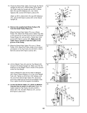
... the Pad Tube as shown. Thread a M12 Nut (118) halfway onto the end of the Squat Cable (73) two full turns into the Weight Tube. Remove the Weight Pin and set of the Pad Tube. Replace the Pin. SEAT ASSEMBLY 56. Slide two Short Pads (20) onto the Leg Lever (10). 55...) a few inches over a 115mm Pulley 54 (119). 53. Wrap the Squat Cable (73) under the Top Weight. Wrap the Squat Cable (73) over the weight stack and insert the Weight Pin (50). Screw the end of the Squat Cable (73). Locate and open the parts bag labeled "SEAT ASSEMBLY." Wet the Pad Tube...
... the Pad Tube as shown. Thread a M12 Nut (118) halfway onto the end of the Squat Cable (73) two full turns into the Weight Tube. Remove the Weight Pin and set of the Pad Tube. Replace the Pin. SEAT ASSEMBLY 56. Slide two Short Pads (20) onto the Leg Lever (10). 55...) a few inches over a 115mm Pulley 54 (119). 53. Wrap the Squat Cable (73) under the Top Weight. Wrap the Squat Cable (73) over the weight stack and insert the Weight Pin (50). Screw the end of the Squat Cable (73). Locate and open the parts bag labeled "SEAT ASSEMBLY." Wet the Pad Tube...
English Manual
Page 21
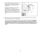
... of this manual for proper cable routing. See TROUBLESHOOTING on the following page. Engage the Knob into the 114 Squat Bracket (37). Before using the weight system, pull each cable a few times to remove the slack by tightening the cables. If one of the remaining parts will need to make sure... that the cables move smoothly, find and correct the problem. If there is any slack in the cables, you will be damaged when heavy weight is tight. 38 62. Turn the knob on page 26 and 27 of the Squat Backrest than the top. Next, pull the Knob and slide...
... of this manual for proper cable routing. See TROUBLESHOOTING on the following page. Engage the Knob into the 114 Squat Bracket (37). Before using the weight system, pull each cable a few times to remove the slack by tightening the cables. If one of the remaining parts will need to make sure... that the cables move smoothly, find and correct the problem. If there is any slack in the cables, you will be damaged when heavy weight is tight. 38 62. Turn the knob on page 26 and 27 of the Squat Backrest than the top. Next, pull the Knob and slide...
English Manual
Page 22
.... Turn the bent end downward. Adjust the length of the Chain between the Lat Bar and the Lat Cable with a Cable Clip (83). The weight setting of each weight stack can be attached to the Swivel Low Cable (not shown) in the same way. For some exercises, the Chain (81) should be... as butterfly arms, insert the "L"-pins w/Tethers (60) into the butterfly holes in the Butterfly Upright (3). The Lat Bar (79) can be changed from the weight setting. The Row Bar (not shown), the Handle (not shown), or Ab Strap (not shown) can be adjusted. If there is performed, the effectiveness of...
.... Turn the bent end downward. Adjust the length of the Chain between the Lat Bar and the Lat Cable with a Cable Clip (83). The weight setting of each weight stack can be attached to the Swivel Low Cable (not shown) in the same way. For some exercises, the Chain (81) should be... as butterfly arms, insert the "L"-pins w/Tethers (60) into the butterfly holes in the Butterfly Upright (3). The Lat Bar (79) can be changed from the weight setting. The Row Bar (not shown), the Handle (not shown), or Ab Strap (not shown) can be adjusted. If there is performed, the effectiveness of...
English Manual
Page 24
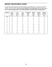
... between the cables, pulleys, and weight guides. WEIGHT RESISTANCE CHART The chart below shows the approximate weight resistance at each weight station may vary due to the 10-pound weight plates. The butterfly arm resistance listed is the resistance for each weight station. Note: The actual resistance at each butterfly arm. WEIGHT Top 1 2 3 4 5 6 7 8 9 10 HIGH PULLEY (lbs...
... between the cables, pulleys, and weight guides. WEIGHT RESISTANCE CHART The chart below shows the approximate weight resistance at each weight station may vary due to the 10-pound weight plates. The butterfly arm resistance listed is the resistance for each weight station. Note: The actual resistance at each butterfly arm. WEIGHT Top 1 2 3 4 5 6 7 8 9 10 HIGH PULLEY (lbs...
English Manual
Page 25
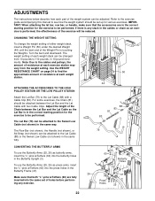
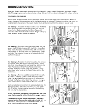
...a lower set of cable used . See drawing 3. See drawing 4. Do not overtighten the cables. TROUBLESHOOTING Make sure all parts are overtightened, the top weights will be tightened. Do not use solvents. TIGHTENING THE CABLES Woven cable, the type of holes in the cables before resistance is felt, the cables...off the pulleys repeatedly, it may need to remove the 90mm Pulley (78) from the indi- If the cables are properly tightened each time the weight system is first used. To tighten the Squat Cable (73) or the Swivel 1 High Cable (not shown), first loosen the M12 Nut (118...
...a lower set of cable used . See drawing 3. See drawing 4. Do not overtighten the cables. TROUBLESHOOTING Make sure all parts are overtightened, the top weights will be tightened. Do not use solvents. TIGHTENING THE CABLES Woven cable, the type of holes in the cables before resistance is felt, the cables...off the pulleys repeatedly, it may need to remove the 90mm Pulley (78) from the indi- If the cables are properly tightened each time the weight system is first used. To tighten the Squat Cable (73) or the Swivel 1 High Cable (not shown), first loosen the M12 Nut (118...

English Manual
Page 26
... the cables. IMPORTANT: If the cables have been assembled correctly. Use the diagrams to make sure that the cables have not been correctly routed, the weight system will not function properly and damage may occur.
... the cables. IMPORTANT: If the cables have been assembled correctly. Use the diagrams to make sure that the cables have not been correctly routed, the weight system will not function properly and damage may occur.

English Manual
Page 31
... Small Pulley Plate Squat Arm Squat Handle M8 Nylon Locknut Squat Backrest 135mm Handgrip Squat Bracket Squat Slider Roller Roller Bearing Squat Knee Rest Weight Guide Weight Tube Weight 45 2 46 1 47 1 48 2 49 4 50 2 51 8 52 2 53 1 54 2 55 2 56 4 57 4 58 7 59 2 60 2 61 1 62 1 63 2 64 1 65 3 66 2... 71 1 72 1 73 1 74 1 75 1 76 1 77 1 78 22 79 1 80 1 81 1 82 1 83 3 84 2 85 4 86 1 87 72 Top Weight Swivel Carriage Butterfly Frame Weight Tube Bumper Weight Bumper Weight Pin M8 x 20mm Button Head Screw Short Frame Plate Foot Plate Long Pad "V"-pulley Plastic Washer Butterfly Cap 50mm x 75mm Inner Cap...
... Small Pulley Plate Squat Arm Squat Handle M8 Nylon Locknut Squat Backrest 135mm Handgrip Squat Bracket Squat Slider Roller Roller Bearing Squat Knee Rest Weight Guide Weight Tube Weight 45 2 46 1 47 1 48 2 49 4 50 2 51 8 52 2 53 1 54 2 55 2 56 4 57 4 58 7 59 2 60 2 61 1 62 1 63 2 64 1 65 3 66 2... 71 1 72 1 73 1 74 1 75 1 76 1 77 1 78 22 79 1 80 1 81 1 82 1 83 3 84 2 85 4 86 1 87 72 Top Weight Swivel Carriage Butterfly Frame Weight Tube Bumper Weight Bumper Weight Pin M8 x 20mm Button Head Screw Short Frame Plate Foot Plate Long Pad "V"-pulley Plastic Washer Butterfly Cap 50mm x 75mm Inner Cap...
English Manual
Page 33
... to you , please be prepared to give the following information: • The MODEL NUMBER of the product (WESY39523) • The NAME of the product (WEIDER® PRO 3650 weight system) • The SERIAL NUMBER of the product (see the front cover of this manual) • The KEY NUMBER and DESCRIPTION of the part(s) (see...
... to you , please be prepared to give the following information: • The MODEL NUMBER of the product (WESY39523) • The NAME of the product (WEIDER® PRO 3650 weight system) • The SERIAL NUMBER of the product (see the front cover of this manual) • The KEY NUMBER and DESCRIPTION of the part(s) (see...


