
English Manual
Page 1
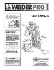
...serial number in this manual before using this manual for future reference. USER'S MANUAL Serial Number Decal (Under Seat) QUESTIONS? As a manufacturer, we will provide immediate assistance, free of charge. MST CAUTION Read all precautions and instructions in the space above for future reference. Patent Pending Visit our website at www.weiderfitness.com new products, prizes, fitness.... Model No. WESY39523 Serial No. If you have questions, or if parts are missing, we are committed to providing complete customer satisfaction. TO AVOID DELAYS, PLEASE CALL DIRECT TO...
...serial number in this manual before using this manual for future reference. USER'S MANUAL Serial Number Decal (Under Seat) QUESTIONS? As a manufacturer, we will provide immediate assistance, free of charge. MST CAUTION Read all precautions and instructions in the space above for future reference. Patent Pending Visit our website at www.weiderfitness.com new products, prizes, fitness.... Model No. WESY39523 Serial No. If you have questions, or if parts are missing, we are committed to providing complete customer satisfaction. TO AVOID DELAYS, PLEASE CALL DIRECT TO...
English Manual
Page 2
WEIDER is a registered trademark of this manual. Remove the PART IDENTIFICATION CHART and the PART LIST/EXPLODED DRAWING before beginning assembly. TABLE OF CONTENTS IMPORTANT PRECAUTIONS 3 BEFORE YOU BEGIN 4 ASSEMBLY 5 ADJUSTMENTS 22 WEIGHT RESISTANCE CHART 24 TROUBLESHOOTING 25 CABLE DIAGRAMS 26 ORDERING REPLACEMENT PARTS Back Cover LIMITED WARRANTY Back Cover Note: A PART IDENTIFICATION CHART and a PART LIST/EXPLODED DRAWING are attached in the center of ICON Health & Fitness, Inc. 2
WEIDER is a registered trademark of this manual. Remove the PART IDENTIFICATION CHART and the PART LIST/EXPLODED DRAWING before beginning assembly. TABLE OF CONTENTS IMPORTANT PRECAUTIONS 3 BEFORE YOU BEGIN 4 ASSEMBLY 5 ADJUSTMENTS 22 WEIGHT RESISTANCE CHART 24 TROUBLESHOOTING 25 CABLE DIAGRAMS 26 ORDERING REPLACEMENT PARTS Back Cover LIMITED WARRANTY Back Cover Note: A PART IDENTIFICATION CHART and a PART LIST/EXPLODED DRAWING are attached in the center of ICON Health & Fitness, Inc. 2
English Manual
Page 3
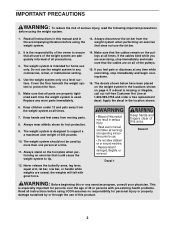
... an exercise that does not use only. If you are exercising, stop immediately and begin cooling down. 16. Replace any exercise program, consult your physician. the weights will fall with pre-existing health problems. Read all instructions in this product. 3 If a decal is especially important for foot protection. 9. Keep hands and fingers clear of the pulleys. 15. Always disconnect the lat bar from moving parts. 8. Decal...
... an exercise that does not use only. If you are exercising, stop immediately and begin cooling down. 16. Replace any exercise program, consult your physician. the weights will fall with pre-existing health problems. Read all instructions in this product. 3 If a decal is especially important for foot protection. 9. Keep hands and fingers clear of the pulleys. 15. Always disconnect the lat bar from moving parts. 8. Decal...
English Manual
Page 4
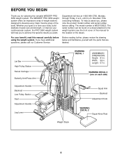
Department toll-free at 1-800-999-3756, Monday through Friday, 6 a.m. The serial number can be found on each side) Weight Stack Squat Arm Backrest Adjustment Knob WARNING DECAL 2 Squat Knee Rest 4 Mountain Time (excluding holidays). Lat Bar High Pulley Station Swivel Carriage Butterfly Arm/Press Arm Adjustment Handle Backrest Low Pulley Station Seat Adjustment Handle Leg Lever WARNING DECAL 1 ASSEMBLED DIMENSIONS: Height: 81 in . WARNING DECAL 2 (one on a decal attached to develop...
Department toll-free at 1-800-999-3756, Monday through Friday, 6 a.m. The serial number can be found on each side) Weight Stack Squat Arm Backrest Adjustment Knob WARNING DECAL 2 Squat Knee Rest 4 Mountain Time (excluding holidays). Lat Bar High Pulley Station Swivel Carriage Butterfly Arm/Press Arm Adjustment Handle Backrest Low Pulley Station Seat Adjustment Handle Leg Lever WARNING DECAL 1 ASSEMBLED DIMENSIONS: Height: 81 in . WARNING DECAL 2 (one on a decal attached to develop...
English Manual
Page 5
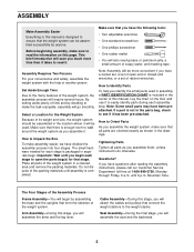
... wrenches, or a set of open the parts bag(s) for each assembly step. Select a Location for the Weight System Because of the Assembly Process Frame Assembly-You will also need grease or petroleum jelly, a small amount of ratchet wrenches. Place all parts are oriented exactly as you assemble the weight system, make the task enjoyable, assembly will attach the cables and pulleys that the weight system can be assembled in the...
... wrenches, or a set of open the parts bag(s) for each assembly step. Select a Location for the Weight System Because of the Assembly Process Frame Assembly-You will also need grease or petroleum jelly, a small amount of ratchet wrenches. Place all parts are oriented exactly as you assemble the weight system, make the task enjoyable, assembly will attach the cables and pulleys that the weight system can be assembled in the...
English Manual
Page 6
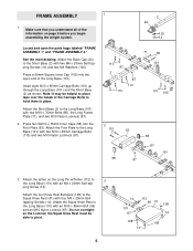
...the Squat Knee Rest (41) with two M10 x 70mm Bolts (85), the Long Frame Plate (71), and two M10 Nylon Locknuts (87). 2. ping Screw (14). Attach the four Knee Rest Bumpers (108) to the Long Base (101) with four M4 x 20mm Selftapping Screws (14). the Squat Knee Rest must be helpful to ...Base (101) with an M10 x 85mm Bolt (96) and an M10 Nylon Locknut (87). Make sure that you begin assembling the weight system. 2 24 120 14 Locate and open end of the information on the Long Pin w/Tether (112) to the Short Base (2) with an M4 x 20mm Self-tap- Attach the Base Cap (24) to 3 the...
...the Squat Knee Rest (41) with two M10 x 70mm Bolts (85), the Long Frame Plate (71), and two M10 Nylon Locknuts (87). 2. ping Screw (14). Attach the four Knee Rest Bumpers (108) to the Long Base (101) with four M4 x 20mm Selftapping Screws (14). the Squat Knee Rest must be helpful to ...Base (101) with an M10 x 85mm Bolt (96) and an M10 Nylon Locknut (87). Make sure that you begin assembling the weight system. 2 24 120 14 Locate and open end of the information on the Long Pin w/Tether (112) to the Short Base (2) with an M4 x 20mm Self-tap- Attach the Base Cap (24) to 3 the...
English Manual
Page 9
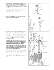
... location shown. Insert the ends of two Weight Guides (42) without 11 holes into the lower end of 9 holes in the same manner. 39 38 39 34 94 39 10. Insert the Weight Tube into the centers of the Weights are facing downward. Attach a Roller (39) between the indicated set of a Weight Tube (43). Make sure that the Top Weight is turned...
... location shown. Insert the ends of two Weight Guides (42) without 11 holes into the lower end of 9 holes in the same manner. 39 38 39 34 94 39 10. Insert the Weight Tube into the centers of the Weights are facing downward. Attach a Roller (39) between the indicated set of a Weight Tube (43). Make sure that the Top Weight is turned...
English Manual
Page 10
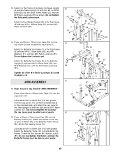
... Top Frame (6) with the Bolt and an M10 Nylon Locknut (87). Attach the Butterfly Frame (47) to the Butterfly Upright (3) with the Bolt and an M10 Nylon Locknut (87). Lubricate an M10 x 80mm Bolt (107) with an M4 x 20mm Self-tapping Screw (14). Do not tighten the Locknuts yet. Open the parts bag labeled "ARM ASSEMBLY." ARM ASSEMBLY 14. Attach the Butterfly Top Frame (7) to...
... Top Frame (6) with the Bolt and an M10 Nylon Locknut (87). Attach the Butterfly Frame (47) to the Butterfly Upright (3) with the Bolt and an M10 Nylon Locknut (87). Lubricate an M10 x 80mm Bolt (107) with an M4 x 20mm Self-tapping Screw (14). Do not tighten the Locknuts yet. Open the parts bag labeled "ARM ASSEMBLY." ARM ASSEMBLY 14. Attach the Butterfly Top Frame (7) to...
English Manual
Page 11
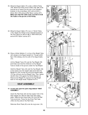
...), and an M10 Nylon Locknut (87) as shown. Lubricate an M10 x 80mm Button Head Bolt (104) and both sides of the Arm. the Butterfly Arm must be able to turn freely. Locate and open the parts bags labeled "CABLE ASSEMBLY" and "PULLEYS." 78 74 30 87 Lubricate the M10 x 165mm Bolt (30) with grease. Locate the Swivel High Cable (74), which is flush with two M10 x 45mm...
...), and an M10 Nylon Locknut (87) as shown. Lubricate an M10 x 80mm Button Head Bolt (104) and both sides of the Arm. the Butterfly Arm must be able to turn freely. Locate and open the parts bags labeled "CABLE ASSEMBLY" and "PULLEYS." 78 74 30 87 Lubricate the M10 x 165mm Bolt (30) with grease. Locate the Swivel High Cable (74), which is flush with two M10 x 45mm...
English Manual
Page 12
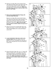
... the Swivel High Cable (74) over a 90mm Pulley (78). Screw the end of the Weight Tube (43). Locate the Swivel Cable (17), which is turned to the second set of holes from the Small Pulley Plates (31). Attach an M10 x 65mm Bolt (18), two M10 Washers (91), and an M10 Nylon Locknut (87) to the Swivel Upright (5). Lift the Weight Tube (43) and...
... the Swivel High Cable (74) over a 90mm Pulley (78). Screw the end of the Weight Tube (43). Locate the Swivel Cable (17), which is turned to the second set of holes from the Small Pulley Plates (31). Attach an M10 x 65mm Bolt (18), two M10 Washers (91), and an M10 Nylon Locknut (87) to the Swivel Upright (5). Lift the Weight Tube (43) and...
English Manual
Page 14
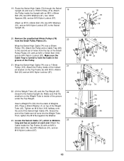
... of holes from the Pulley Plates (63). Remove the preattached 90mm Pulleys (78) 30 from the top of the Pulley. 31. Wrap the Lat Cable (88) around a 90mm Pulley 29 (78). Attach the end of the Lat Cable (88) inside of the Pulley. 30. Make sure the Cable Trap is turned to the indicated bracket on the Left Butterfly Arm (25) with an M10...
... of holes from the Pulley Plates (63). Remove the preattached 90mm Pulleys (78) 30 from the top of the Pulley. 31. Wrap the Lat Cable (88) around a 90mm Pulley 29 (78). Attach the end of the Lat Cable (88) inside of the Pulley. 30. Make sure the Cable Trap is turned to the indicated bracket on the Left Butterfly Arm (25) with an M10...
English Manual
Page 15
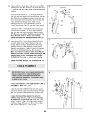
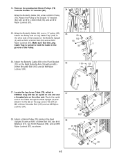
...). 38. Locate the Leg Lever Cable (75), which is turned to the Pivot Bracket 36 (70) on the Leg Lever (10) with an M8 x 20mm Shoulder Bolt (103) and an M8 Nylon Locknut (34). 103 69 70 26 34 37. Route the eyelet end of the Cable through the Seat Upright (9) and attach it to 59 the other end. Attach the Pulley to...
...). 38. Locate the Leg Lever Cable (75), which is turned to the Pivot Bracket 36 (70) on the Leg Lever (10) with an M8 x 20mm Shoulder Bolt (103) and an M8 Nylon Locknut (34). 103 69 70 26 34 37. Route the eyelet end of the Cable through the Seat Upright (9) and attach it to 59 the other end. Attach the Pulley to...
English Manual
Page 19
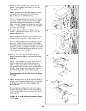
...). Locate and open the parts bag labeled "SEAT ASSEMBLY." Make sure that the small pin on the weight stack. Remove the Weight Pin and set of holes from the top in the Seat Upright (9). Insert the Pad Tube (23) into the square hole in the indicated bracket on top of the Squat Cable (73). Then, tighten the M12 Nut (118) against the 50mm Washer (1). Attach the Pulley...
...). Locate and open the parts bag labeled "SEAT ASSEMBLY." Make sure that the small pin on the weight stack. Remove the Weight Pin and set of holes from the top in the Seat Upright (9). Insert the Pad Tube (23) into the square hole in the indicated bracket on top of the Squat Cable (73). Then, tighten the M12 Nut (118) against the 50mm Washer (1). Attach the Pulley...
English Manual
Page 20
... (8). Do not tighten the Locknuts yet. Finish attaching the Squat Arm (32) to the Seat Bracket (11) with soapy water. 57. Attach the Seat (16) to the Squat Bracket (37) with four M6 x 16mm Screws (114). Press two 20mm x 40mm Inner Caps (116) and a 58 25mm x 40mm Square Inner Cap (117) into the Butterfly Upright (3). Wet one of the...
... (8). Do not tighten the Locknuts yet. Finish attaching the Squat Arm (32) to the Seat Bracket (11) with soapy water. 57. Attach the Seat (16) to the Squat Bracket (37) with four M6 x 16mm Screws (114). Press two 20mm x 40mm Inner Caps (116) and a 58 25mm x 40mm Square Inner Cap (117) into the Butterfly Upright (3). Wet one of the...
English Manual
Page 21
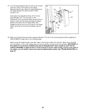
... Bracket (37). Before using the weight system, pull each cable a few times to loosen it is used. See the CABLE DIAGRAMS on page 25. 21 The use of the remaining parts will need to the bottom of this manual for proper cable routing. Turn the knob on the following page. IMPORTANT: If the cables are closer to remove the slack by tightening the cables. If there is any...
... Bracket (37). Before using the weight system, pull each cable a few times to loosen it is used. See the CABLE DIAGRAMS on page 25. 21 The use of the remaining parts will need to the bottom of this manual for proper cable routing. Turn the knob on the following page. IMPORTANT: If the cables are closer to remove the slack by tightening the cables. If there is any...
English Manual
Page 22
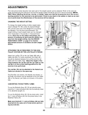
... THE LOW PULLEY STATION Attach the Lat Bar (79) to the cables and pulleys, the amount of resistance at each weight station. ADJUSTMENTS The instructions below describe how each part of the weight system can be attached between the Lat Bar and the Lat Cable so the Lat Bar is in the correct starting position for the exercise to 110 pounds, in 10-pound increments. Refer to the exercise guide accompanying this manual to...
... THE LOW PULLEY STATION Attach the Lat Bar (79) to the cables and pulleys, the amount of resistance at each weight station. ADJUSTMENTS The instructions below describe how each part of the weight system can be attached between the Lat Bar and the Lat Cable so the Lat Bar is in the correct starting position for the exercise to 110 pounds, in 10-pound increments. Refer to the exercise guide accompanying this manual to...
English Manual
Page 24
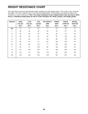
WEIGHT RESISTANCE CHART The chart below shows the approximate weight resistance at each weight station. "Top" refers to the 10-pound weight plates. Note: The actual resistance at each weight station may vary due to differences in individual weight plates as well as friction between the cables, pulleys, and weight guides. The other numbers refer to the 10-pound top weight. WEIGHT Top 1 2 3 4 5 6 7 8 9 10 HIGH PULLEY (lbs.) 14 25 38...
WEIGHT RESISTANCE CHART The chart below shows the approximate weight resistance at each weight station. "Top" refers to the 10-pound weight plates. Note: The actual resistance at each weight station may vary due to differences in individual weight plates as well as friction between the cables, pulleys, and weight guides. The other numbers refer to the 10-pound top weight. WEIGHT Top 1 2 3 4 5 6 7 8 9 10 HIGH PULLEY (lbs.) 14 25 38...
English Manual
Page 25
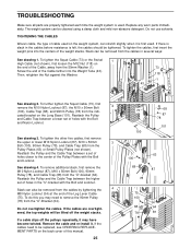
... this manual. 25 73 68 87 78 101 100 63 100 68 87 78 75 100 34 68 64 78 87 If the cables need to be tightened. Replace any worn parts immediately. Reattach the Pulley and Cable Trap between a lower set of holes in the cables before resistance is slack in the "U"-bracket with the Bolt and Locknut. Reattach the Pulley and the Cable...
... this manual. 25 73 68 87 78 101 100 63 100 68 87 78 75 100 34 68 64 78 87 If the cables need to be tightened. Replace any worn parts immediately. Reattach the Pulley and Cable Trap between a lower set of holes in the cables before resistance is slack in the "U"-bracket with the Bolt and Locknut. Reattach the Pulley and the Cable...
English Manual
Page 31
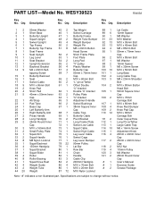
... Button Head Bolt 50mm Square Inner Cap M10 x 70mm Carriage Bolt M10 x 80mm Bolt Knee Rest Bumper Knee Pad Cap M10 x 65mm Carriage Bolt Outer Cap w/Hole Long Pin w/Tether Large Cable Trap M6 x 16mm Screw Adjustment Knob 20mm x 40mm Inner Cap 25mm x 40mm Inner Cap M12 Nut 115mm Pulley M4 Washer 25mm Round Outer Cap User's Manual Exercise Guide Grease Package Note: "#" indicates a non-illustrated part...
... Button Head Bolt 50mm Square Inner Cap M10 x 70mm Carriage Bolt M10 x 80mm Bolt Knee Rest Bumper Knee Pad Cap M10 x 65mm Carriage Bolt Outer Cap w/Hole Long Pin w/Tether Large Cable Trap M6 x 16mm Screw Adjustment Knob 20mm x 40mm Inner Cap 25mm x 40mm Inner Cap M12 Nut 115mm Pulley M4 Washer 25mm Round Outer Cap User's Manual Exercise Guide Grease Package Note: "#" indicates a non-illustrated part...
English Manual
Page 33
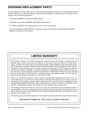
... all other rights which warranty claims are made must be free from the date of this manual) LIMITED WARRANTY ICON Health & Fitness, Inc. (ICON), warrants this manual) • The KEY NUMBER and DESCRIPTION of the part(s) (see the PART LIST and EXPLODED DRAWING attached in the center of purchase. products used as store display models. You may not apply to you , please be prepared to replacing or repairing, at 1-800-999...
... all other rights which warranty claims are made must be free from the date of this manual) LIMITED WARRANTY ICON Health & Fitness, Inc. (ICON), warrants this manual) • The KEY NUMBER and DESCRIPTION of the part(s) (see the PART LIST and EXPLODED DRAWING attached in the center of purchase. products used as store display models. You may not apply to you , please be prepared to replacing or repairing, at 1-800-999...


