
English Manual
Page 2
WEIDER is a registered trademark of this manual. TABLE OF CONTENTS IMPORTANT PRECAUTIONS 3 BEFORE YOU BEGIN 4 ASSEMBLY 5 ADJUSTMENTS 22 WEIGHT RESISTANCE CHART 24 TROUBLESHOOTING 25 CABLE DIAGRAMS 26 ORDERING REPLACEMENT PARTS Back Cover LIMITED WARRANTY Back Cover Note: A PART IDENTIFICATION CHART and a PART LIST/EXPLODED DRAWING are attached in the center of ICON Health & Fitness, Inc. 2 Remove the PART IDENTIFICATION CHART and the PART LIST/EXPLODED DRAWING before beginning assembly.
WEIDER is a registered trademark of this manual. TABLE OF CONTENTS IMPORTANT PRECAUTIONS 3 BEFORE YOU BEGIN 4 ASSEMBLY 5 ADJUSTMENTS 22 WEIGHT RESISTANCE CHART 24 TROUBLESHOOTING 25 CABLE DIAGRAMS 26 ORDERING REPLACEMENT PARTS Back Cover LIMITED WARRANTY Back Cover Note: A PART IDENTIFICATION CHART and a PART LIST/EXPLODED DRAWING are attached in the center of ICON Health & Fitness, Inc. 2 Remove the PART IDENTIFICATION CHART and the PART LIST/EXPLODED DRAWING before beginning assembly.
English Manual
Page 4
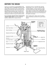
... Bar High Pulley Station Swivel Carriage Butterfly Arm/Press Arm Adjustment Handle Backrest Low Pulley Station Seat Adjustment Handle Leg Lever WARNING DECAL 1 ASSEMBLED DIMENSIONS: Height: 81 in . If you to the weight system (see the front cover of this manual carefully before calling. Width... and serial number before using the weight system. Department toll-free at 1-800-999-3756, Monday through Friday, 6 a.m. The WEIDER® PRO 3650 weight system offers an impressive array of weight stations designed to tone your body, build dramatic muscle size and strength, or improve your...
... Bar High Pulley Station Swivel Carriage Butterfly Arm/Press Arm Adjustment Handle Backrest Low Pulley Station Seat Adjustment Handle Leg Lever WARNING DECAL 1 ASSEMBLED DIMENSIONS: Height: 81 in . If you to the weight system (see the front cover of this manual carefully before calling. Width... and serial number before using the weight system. Department toll-free at 1-800-999-3756, Monday through Friday, 6 a.m. The WEIDER® PRO 3650 weight system offers an impressive array of weight stations designed to tone your body, build dramatic muscle size and strength, or improve your...
English Manual
Page 5
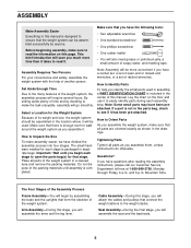
...all parts as shown in the drawings. Lay the chart on this page. Note: Some small parts may have questions after reading the assembly instructions, please call our Customer Service Department toll-free at 1-800-999-3756, Monday through Friday, 6 a.m. This brief introduction will go...ensure that connect the weight stations to easily identify parts during each stage to the many features of soapy water, and masking tape. Arm Assembly-During this stage, you have the following tools: • Two adjustable wrenches • One standard screwdriver • One phillips screwdriver &#...
...all parts as shown in the drawings. Lay the chart on this page. Note: Some small parts may have questions after reading the assembly instructions, please call our Customer Service Department toll-free at 1-800-999-3756, Monday through Friday, 6 a.m. This brief introduction will go...ensure that connect the weight stations to easily identify parts during each stage to the many features of soapy water, and masking tape. Arm Assembly-During this stage, you have the following tools: • Two adjustable wrenches • One standard screwdriver • One phillips screwdriver &#...
English Manual
Page 6
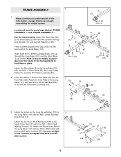
... M4 x 20mm Selftapping Screws (14). See the inset drawing. Press two 50mm x 75mm Inner Caps (58) into the open the parts bags labeled "FRAME ASSEMBLY 1" and "FRAME ASSEMBLY 2." ping Screw (14). Do not overtighten the Locknut; Insert eight M10 x 65mm Carriage Bolts (110) up through the Long Base (101) and the Short... Base (101). Note: It may be able to 3 the Long Base (101) with an M10 x 85mm Bolt (96) and an M10 Nylon Locknut (87). FRAME ASSEMBLY 1 1. Make sure that you understand all of the information on the Long Pin w/Tether (112) to pivot. 6 14 101 87 112 96 41 108 14...
... M4 x 20mm Selftapping Screws (14). See the inset drawing. Press two 50mm x 75mm Inner Caps (58) into the open the parts bags labeled "FRAME ASSEMBLY 1" and "FRAME ASSEMBLY 2." ping Screw (14). Do not overtighten the Locknut; Insert eight M10 x 65mm Carriage Bolts (110) up through the Long Base (101) and the Short... Base (101). Note: It may be able to 3 the Long Base (101) with an M10 x 85mm Bolt (96) and an M10 Nylon Locknut (87). FRAME ASSEMBLY 1 1. Make sure that you understand all of the information on the Long Pin w/Tether (112) to pivot. 6 14 101 87 112 96 41 108 14...
English Manual
Page 9
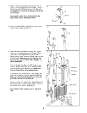
Slide the Top Weight onto the Weight Guides (42). Assemble the other weight stack in the same way. 9 4 42 42 45 Lubricate "10" Decal 43 Groove 48 44 "20" Decal "110" Decal 49 101 Next, ... Top Weight (45) in a Top Weight (45). Make sure that the Weight Tube is facing downward. Slide two Weight Bumpers (49) onto the Weight Guides. Assemble the other three Rollers (39) to the Squat Slider (38) in the Squat Slider (38) with the numbers 20 through 110 to roll easily. Do...
Slide the Top Weight onto the Weight Guides (42). Assemble the other weight stack in the same way. 9 4 42 42 45 Lubricate "10" Decal 43 Groove 48 44 "20" Decal "110" Decal 49 101 Next, ... Top Weight (45) in a Top Weight (45). Make sure that the Weight Tube is facing downward. Slide two Weight Bumpers (49) onto the Weight Guides. Assemble the other three Rollers (39) to the Squat Slider (38) in the Squat Slider (38) with the numbers 20 through 110 to roll easily. Do...
English Manual
Page 10
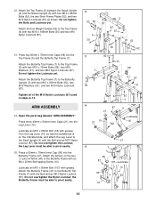
... (91), and two M10 Nylon Locknuts (87). Attach the Top Frame (6) between the Squat Upright (4) and the Swivel Upright (5) with grease. ARM ASSEMBLY 14. Open the parts bag labeled "ARM ASSEMBLY." 12. Press two 50mm x 75mm Inner Caps (58) into the Leg Lever (10). Lubricate an M10 x 80mm Bolt (107) with four...
... (91), and two M10 Nylon Locknuts (87). Attach the Top Frame (6) between the Squat Upright (4) and the Swivel Upright (5) with grease. ARM ASSEMBLY 14. Open the parts bag labeled "ARM ASSEMBLY." 12. Press two 50mm x 75mm Inner Caps (58) into the Leg Lever (10). Lubricate an M10 x 80mm Bolt (107) with four...
English Manual
Page 11
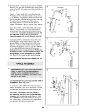
... be able to the Cable Identification 18 Chart on the other end. IMPORTANT: Refer to turn freely. Locate and open the parts bags labeled "CABLE ASSEMBLY" and "PULLEYS." 78 74 30 87 Lubricate the M10 x 165mm Bolt (30) with soapy water. Wrap the Cable around a 90mm Pulley (78). Wet the lower...). 16 26 51 54 Lubricate 100 70 87 21 29 25 28 27 17 104 26 56 91 57 57 91 87 47 25 CABLE ASSEMBLY 18. Do not overtighten the bolts and nuts attaching the pulleys. Locate the Swivel High Cable (74), which is flush with the Bolt, the two...
... be able to the Cable Identification 18 Chart on the other end. IMPORTANT: Refer to turn freely. Locate and open the parts bags labeled "CABLE ASSEMBLY" and "PULLEYS." 78 74 30 87 Lubricate the M10 x 165mm Bolt (30) with soapy water. Wrap the Cable around a 90mm Pulley (78). Wet the lower...). 16 26 51 54 Lubricate 100 70 87 21 29 25 28 27 17 104 26 56 91 57 57 91 87 47 25 CABLE ASSEMBLY 18. Do not overtighten the bolts and nuts attaching the pulleys. Locate the Swivel High Cable (74), which is flush with the Bolt, the two...
English Manual
Page 19
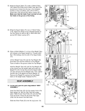
... Tube (43) and the Top Weight (45) a few inches over a 115mm Pulley 54 (119). Replace the Pin. Locate and open the parts bag labeled "SEAT ASSEMBLY." Press the two Knee Pad Caps (109) into the ends of the Weight Tube (43) closest to hold the Cable in the Seat Upright (9). 53... Pad Tube. Remove the Weight Pin and set of holes from the top in the indicated bracket on the Top Frame (6) with soapy water. SEAT ASSEMBLY 56. Lift the Weight Tube (43) and the Top Weight (45) and make sure that the Cable Trap is inside of the Pulley. 54. Insert...
... Tube (43) and the Top Weight (45) a few inches over a 115mm Pulley 54 (119). Replace the Pin. Locate and open the parts bag labeled "SEAT ASSEMBLY." Press the two Knee Pad Caps (109) into the ends of the Weight Tube (43) closest to hold the Cable in the Seat Upright (9). 53... Pad Tube. Remove the Weight Pin and set of holes from the top in the indicated bracket on the Top Frame (6) with soapy water. SEAT ASSEMBLY 56. Lift the Weight Tube (43) and the Top Weight (45) and make sure that the Cable Trap is inside of the Pulley. 54. Insert...

English Manual
Page 26
... CABLE DIAGRAMS The cable identification chart below shows the ends of each cable and the lengths of the cables. IMPORTANT: If the cables have been assembled correctly. The cable diagrams on this page and the following page show the routes of the cables.
... CABLE DIAGRAMS The cable identification chart below shows the ends of each cable and the lengths of the cables. IMPORTANT: If the cables have been assembled correctly. The cable diagrams on this page and the following page show the routes of the cables.


