
English Manual
Page 1
Serial Number Decal (under seat) QUESTIONS? WESY9975.0 Serial No. CALL TOLL-FREE: 1-877-992-5999 Mon.-Fri., 6 a.m.-6 p.m. As a manufacturer, we are committed to providing complete customer satisfaction. Save this equipment. If you have questions, or if a part is damaged or missing, PLEASE CONTACT OUR CUSTOMER SERVICE DEPARTMENT DIRECTLY. MST ON THE WEB: www.weiderservice.com CAUTION Read all precautions and instructions in the space above for future reference. USER'S MANUAL Visit our website at www.weiderfitness.com new products, prizes, fitness tips, and much more! Model ...
Serial Number Decal (under seat) QUESTIONS? WESY9975.0 Serial No. CALL TOLL-FREE: 1-877-992-5999 Mon.-Fri., 6 a.m.-6 p.m. As a manufacturer, we are committed to providing complete customer satisfaction. Save this equipment. If you have questions, or if a part is damaged or missing, PLEASE CONTACT OUR CUSTOMER SERVICE DEPARTMENT DIRECTLY. MST ON THE WEB: www.weiderservice.com CAUTION Read all precautions and instructions in the space above for future reference. USER'S MANUAL Visit our website at www.weiderfitness.com new products, prizes, fitness tips, and much more! Model ...
English Manual
Page 2
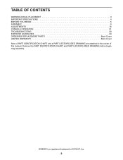
TABLE OF CONTENTS WARNING DECAL PLACEMENT 3 IMPORTANT PRECAUTIONS 4 BEFORE YOU BEGIN 5 ASSEMBLY 6 ADJUSTMENTS 16 CONSOLE OPERATION 21 TROUBLESHOOTING 23 EXERCISE GUIDELINES 24 ORDERING REPLACEMENT PARTS Back Cover LIMITED WARRANTY Back Cover Note: A PART IDENTIFICATION CHART and a PART LIST/EXPLODED DRAWING are attached in the center of ICON IP, Inc. 2 WEIDER is a registered trademark of this manual. Remove the PART IDENTIFICATION CHART and PART LIST/EXPLODED DRAWING before beginning assembly.
TABLE OF CONTENTS WARNING DECAL PLACEMENT 3 IMPORTANT PRECAUTIONS 4 BEFORE YOU BEGIN 5 ASSEMBLY 6 ADJUSTMENTS 16 CONSOLE OPERATION 21 TROUBLESHOOTING 23 EXERCISE GUIDELINES 24 ORDERING REPLACEMENT PARTS Back Cover LIMITED WARRANTY Back Cover Note: A PART IDENTIFICATION CHART and a PART LIST/EXPLODED DRAWING are attached in the center of ICON IP, Inc. 2 WEIDER is a registered trademark of this manual. Remove the PART IDENTIFICATION CHART and PART LIST/EXPLODED DRAWING before beginning assembly.

English Manual
Page 3
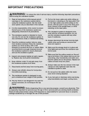
Keep hands and fingers clear of this area. 3 Apply the decal in the location shown. WARNING DECAL PLACEMENT The decals shown here have been placed on the front cover of this manual and order a free replacement decal. If a decal is missing or illegible, please call the toll-free telephone number on the resistance system.
Keep hands and fingers clear of this area. 3 Apply the decal in the location shown. WARNING DECAL PLACEMENT The decals shown here have been placed on the front cover of this manual and order a free replacement decal. If a decal is missing or illegible, please call the toll-free telephone number on the resistance system.
English Manual
Page 4
Inspect and properly tighten all times. 7. The top frame is used with the included resistance. Make sure the storage knob is in this or any worn parts immediately. 6. Place the resistance system on the pulleys at all cables at all parts regularly. Make sure that there is being adjusted. 18. Keep children under 12 and pets away from the high cables when performing an exercise that all precautions. 3. Pull on the lower cable only while sitting on the bench or standing on the top frame. 11. Do not use the resistance system with a mat beneath it . 14. Make sure ...
Inspect and properly tighten all times. 7. The top frame is used with the included resistance. Make sure the storage knob is in this or any worn parts immediately. 6. Place the resistance system on the pulleys at all cables at all parts regularly. Make sure that there is being adjusted. 18. Keep children under 12 and pets away from the high cables when performing an exercise that all precautions. 3. Pull on the lower cable only while sitting on the bench or standing on the top frame. 11. Do not use the resistance system with a mat beneath it . 14. Make sure ...
English Manual
Page 5
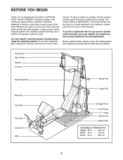
... number can be found on a decal attached to develop every major muscle group of the body. To avoid a registration fee for selecting the innovative PLATINUM PLUS 1000 BY WEIDER® resistance system. BEFORE YOU BEGIN Thank you for any service needed under warranty, you must register the weight system at www.weiderservice.com/registration...
... number can be found on a decal attached to develop every major muscle group of the body. To avoid a registration fee for selecting the innovative PLATINUM PLUS 1000 BY WEIDER® resistance system. BEFORE YOU BEGIN Thank you for any service needed under warranty, you must register the weight system at www.weiderservice.com/registration...
English Manual
Page 6
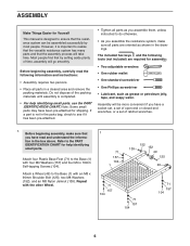
However, it has been pre-attached. • Tighten all parts as you assemble them, unless instructed to do otherwise. • As you have a socket set, a set of open-end or closed-end wrenches, or a set of the packing materials until assembly is completed. • For help identifying small parts. Most people find that the assembly process will be more convenient if you assemble the resistance system, make sure that the resistance system can be assembled successfully by setting aside plenty of time, assembly will go smoothly. Assembly will take time. Before beginning ...
However, it has been pre-attached. • Tighten all parts as you assemble them, unless instructed to do otherwise. • As you have a socket set, a set of open-end or closed-end wrenches, or a set of the packing materials until assembly is completed. • For help identifying small parts. Most people find that the assembly process will be more convenient if you assemble the resistance system, make sure that the resistance system can be assembled successfully by setting aside plenty of time, assembly will go smoothly. Assembly will take time. Before beginning ...

English Manual
Page 7
2. Connect the Upright Base (2) to the Base with two M10 x 67mm Bolts (111) and two M10 Nylon Locknuts (112). Untie the loose end of the Rope (70) through a Rope Cover (169) and a Link (167) as shown. Hand tighten two M14 Nylon Locknuts (127) onto the Bolts. 3. Route the loose end of the Rope and route it through the Left Arm Frame (8) and a Swivel Arm (29). Insert two M10 x 65mm Carriage Bolts (103) up through the Right Arm Frame (171) and the Upright Base (2). Place a piece of the Rope (70) is connected to hold them in the Rope Cover is under the connected end of Rope ...
2. Connect the Upright Base (2) to the Base with two M10 x 67mm Bolts (111) and two M10 Nylon Locknuts (112). Untie the loose end of the Rope (70) through a Rope Cover (169) and a Link (167) as shown. Hand tighten two M14 Nylon Locknuts (127) onto the Bolts. 3. Route the loose end of the Rope and route it through the Left Arm Frame (8) and a Swivel Arm (29). Insert two M10 x 65mm Carriage Bolts (103) up through the Right Arm Frame (171) and the Upright Base (2). Place a piece of the Rope (70) is connected to hold them in the Rope Cover is under the connected end of Rope ...
English Manual
Page 8
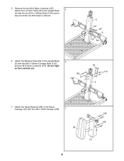
Remove the two M14 Nylon Locknuts (127). 5 Attach the Left Arm Frame (8) to the Upright Base (2) with two M10 x 65mm Carriage Bolts (103) and two M10 Nylon Locknuts (112). en the Locknuts yet. 103 59 112 2 7. 5. Do not tight- Attach the Backing Plate (59) to the Squat Carriage (10) with four M6 x 16mm Screws (108). 7 28 8 108 108 10 Attach the Squat Backrest (28) to the Upright Base 6 (2) with the two M14 x 155mm Bolts (107) used in step 2 and the two M14 Nylon Locknuts. 2 107 127 8 107 127 6.
Remove the two M14 Nylon Locknuts (127). 5 Attach the Left Arm Frame (8) to the Upright Base (2) with two M10 x 65mm Carriage Bolts (103) and two M10 Nylon Locknuts (112). en the Locknuts yet. 103 59 112 2 7. 5. Do not tight- Attach the Backing Plate (59) to the Squat Carriage (10) with four M6 x 16mm Screws (108). 7 28 8 108 108 10 Attach the Squat Backrest (28) to the Upright Base 6 (2) with the two M14 x 155mm Bolts (107) used in step 2 and the two M14 Nylon Locknuts. 2 107 127 8 107 127 6.
English Manual
Page 9
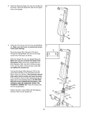
Make sure you do not pinch the Upper Wire Harnesses (172). IF THE CONNECTOR IS NOT INSERTED PROPERLY, THE CONSOLE MAY BE DAMAGED WHEN THE POWER IS TURNED ON. Press the Front Cover (31) onto the Upright Base 9 (2). Do not tighten the Screws yet. Connect the Upper Wire Harness (172) to the Lower Wire Harness (173) extending from the Mech Frame (not shown). Tighten two M4 x 16mm White ZP Self-tapping Screws (159) into place. Make sure the Cover is oriented as shown. Secure the Upright with two M10 Washers (129), two M10 x 20mm Screws (113), and two M10 x 25mm Screws (105). The ...
Make sure you do not pinch the Upper Wire Harnesses (172). IF THE CONNECTOR IS NOT INSERTED PROPERLY, THE CONSOLE MAY BE DAMAGED WHEN THE POWER IS TURNED ON. Press the Front Cover (31) onto the Upright Base 9 (2). Do not tighten the Screws yet. Connect the Upper Wire Harness (172) to the Lower Wire Harness (173) extending from the Mech Frame (not shown). Tighten two M4 x 16mm White ZP Self-tapping Screws (159) into place. Make sure the Cover is oriented as shown. Secure the Upright with two M10 Washers (129), two M10 x 20mm Screws (113), and two M10 x 25mm Screws (105). The ...
English Manual
Page 10
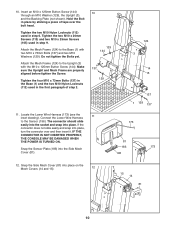
Tighten the two M10 Nylon Locknuts (112) used in step 6. IF THE CONNECTOR IS NOT INSERTED PROPERLY, THE CONSOLE MAY BE DAMAGED WHEN THE POWER IS TURNED ON. Snap the Sensor Plate (183) into place on the Mech Covers (14 and 15). 12 15 14 81 10 Insert an M10 x 125mm Button Screw (144) through an M10 Washer (129), the Upright (3), and the Backing Plate (not shown). Tighten the two M10 x 20mm Screws (113) and two M10 x 25mm Screws (105) used in step 9. Tighten the four M10 x 73mm Bolts (137) in the Base (1) and the two M10 Nylon Locknuts (112) used in place by sticking a piece of...
Tighten the two M10 Nylon Locknuts (112) used in step 6. IF THE CONNECTOR IS NOT INSERTED PROPERLY, THE CONSOLE MAY BE DAMAGED WHEN THE POWER IS TURNED ON. Snap the Sensor Plate (183) into place on the Mech Covers (14 and 15). 12 15 14 81 10 Insert an M10 x 125mm Button Screw (144) through an M10 Washer (129), the Upright (3), and the Backing Plate (not shown). Tighten the two M10 x 20mm Screws (113) and two M10 x 25mm Screws (105) used in step 9. Tighten the four M10 x 73mm Bolts (137) in the Base (1) and the two M10 Nylon Locknuts (112) used in place by sticking a piece of...
English Manual
Page 11
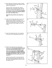
13. Slide the Foam Pad onto the Squat Arm. 137 Grease Grease an M10 x 73mm Bolt (137). SOLE MAY BE DAMAGED WHEN THE POWER IS TURNED ON. Push the excess wire into the Upright, over and then insert it over the Top Frame. 20 Mark 3 46 117 129 15. Attach the Top Frame to the Upright (3) with two M4 x 80mm Self-tapping Screws (145), two M4 x 65mm Self-tapping Screws (158), and four M4 Washers (157). 158 157 172 145 3 157 11 TOR IS NOT INSERTED PROPERLY, THE CON- Do not overtighten the Locknut; Press the Plastic Cap (46) into the Upright (3). 21 Attach the ...
13. Slide the Foam Pad onto the Squat Arm. 137 Grease Grease an M10 x 73mm Bolt (137). SOLE MAY BE DAMAGED WHEN THE POWER IS TURNED ON. Push the excess wire into the Upright, over and then insert it over the Top Frame. 20 Mark 3 46 117 129 15. Attach the Top Frame to the Upright (3) with two M4 x 80mm Self-tapping Screws (145), two M4 x 65mm Self-tapping Screws (158), and four M4 Washers (157). 158 157 172 145 3 157 11 TOR IS NOT INSERTED PROPERLY, THE CON- Do not overtighten the Locknut; Press the Plastic Cap (46) into the Upright (3). 21 Attach the ...

English Manual
Page 12
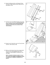
Do not overtighten the Locknut; Orient the Seat (25) as shown. Note: The front of the Front Leg Foot is taller 38 12 Tighten the Storage Knob (44) into the 112 Attach at this hole 2 Upright Base (2) and the Rail (5). 5 Holes 19 18. Attach the Rail to the Rail (5) with an M10 x 106mm Bolt (19) and an M10 Nylon Locknut (112). Press the Front Leg Foot (38) onto the Front Leg 19 (4). 17. the Rail must be able to 18 the Seat Carriage (16) with the holes on the side 17 shown. Attach the Front Leg (4) to the Upright Base (2) 44 with four M8 x 20mm Screws (95) and four M8...
Do not overtighten the Locknut; Orient the Seat (25) as shown. Note: The front of the Front Leg Foot is taller 38 12 Tighten the Storage Knob (44) into the 112 Attach at this hole 2 Upright Base (2) and the Rail (5). 5 Holes 19 18. Attach the Rail to the Rail (5) with an M10 x 106mm Bolt (19) and an M10 Nylon Locknut (112). Press the Front Leg Foot (38) onto the Front Leg 19 (4). 17. the Rail must be able to 18 the Seat Carriage (16) with the holes on the side 17 shown. Attach the Front Leg (4) to the Upright Base (2) 44 with four M8 x 20mm Screws (95) and four M8...

English Manual
Page 13
Make sure the parts are pressed against the bottom of the Rail and properly tighten the indicated M8 Nylon Jamnut (139). Make sure that the wide sides of all six Seat Wheels (74) are oriented as it will go, and set the Seat Carriage (16) on the Seat (25), hold the bottom Seat Wheels firmly against the Rail (5). Attach the Leg Lever (13) to the bottom holes in the Seat Carriage (16) with a Leg Lever Pin (91) and a Cotter Pin (90). 22 123 74 122 74 Wide Side 123 74 74 5 74 74 139 138 90 91 13 4 13 While a second person presses down on the Bench Rail (5). 20 119 Loosely ...
Make sure the parts are pressed against the bottom of the Rail and properly tighten the indicated M8 Nylon Jamnut (139). Make sure that the wide sides of all six Seat Wheels (74) are oriented as it will go, and set the Seat Carriage (16) on the Seat (25), hold the bottom Seat Wheels firmly against the Rail (5). Attach the Leg Lever (13) to the bottom holes in the Seat Carriage (16) with a Leg Lever Pin (91) and a Cotter Pin (90). 22 123 74 122 74 Wide Side 123 74 74 5 74 74 139 138 90 91 13 4 13 While a second person presses down on the Bench Rail (5). 20 119 Loosely ...

English Manual
Page 14
Attach a 90mm Pulley (92) inside the Leg Lever (13) with two M4 x 16mm Self-tapping Screws (104). Insert the two Short Pad Tubes (32) into the Leg Lever (13). Attach a Bumper (168) to the Backrest Frame (17) with an M10 x 92mm Bolt (116), two M10 Washers (129), two 25mm Spacers (130), and an M10 Nylon Locknut (112). 23 90 13 72 91 112 130 129 4 92 72 129 130 116 24. Attach the Right Pinch Guard (42) to the Backrest Frame (17) with a Leg Lever Pin (91) and a Cotter Pin (90). Slide two Large Foam Pads (37) onto each Short Pad Tube. Repeat this step with two M4 x 9mm ...
Attach a 90mm Pulley (92) inside the Leg Lever (13) with two M4 x 16mm Self-tapping Screws (104). Insert the two Short Pad Tubes (32) into the Leg Lever (13). Attach a Bumper (168) to the Backrest Frame (17) with an M10 x 92mm Bolt (116), two M10 Washers (129), two 25mm Spacers (130), and an M10 Nylon Locknut (112). 23 90 13 72 91 112 130 129 4 92 72 129 130 116 24. Attach the Right Pinch Guard (42) to the Backrest Frame (17) with a Leg Lever Pin (91) and a Cotter Pin (90). Slide two Large Foam Pads (37) onto each Short Pad Tube. Repeat this step with two M4 x 9mm ...
English Manual
Page 15
26. Hold the Backrest Frame vertically over the Seat Carriage and 17 slide the rod into the 27 slot in ADJUSTMENTS, beginning on the next page. Attach the Curl Pad (26) to the Backrest Frame (17) with 28 two M6 x 16mm Screws (108). 29. Make sure that all parts have been properly tightened. Attach the Backrest (24) to the Curl Post (12) with four M6 x 38mm Screws (128) and four 26 M6 Washers (126). 24 27. Before using the resistance system, turn on the console and change the resistance setting as shown in CONSOLE OPERATION on the Backrest Frame (17) into the slot,...
26. Hold the Backrest Frame vertically over the Seat Carriage and 17 slide the rod into the 27 slot in ADJUSTMENTS, beginning on the next page. Attach the Curl Pad (26) to the Backrest Frame (17) with 28 two M6 x 16mm Screws (108). 29. Make sure that all parts have been properly tightened. Attach the Backrest (24) to the Curl Post (12) with four M6 x 38mm Screws (128) and four 26 M6 Washers (126). 24 27. Before using the resistance system, turn on the console and change the resistance setting as shown in CONSOLE OPERATION on the Backrest Frame (17) into the slot,...
English Manual
Page 16
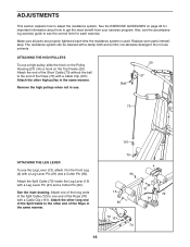
Make sure all parts are properly tightened each exercise. ATTACHING THE HIGH PULLEYS To use solvents. Attach the other end of the Rope in the same manner. 70 90 13 90 72 161 70 16 4 91 72 91 Attach one end of the Rope (70) with a Cable Clip (161). ADJUSTMENTS This section explains how to one of the long ends of the Split Cable (72) to adjust the resistance system. See the EXERCISE GUIDELINES on the Top Frame (20). The resistance system can be cleaned with a Leg Lever Pin (91) and a Cotter Pin (90). Attach the other long end of the Split Cable to the other high pulley in use. ...
Make sure all parts are properly tightened each exercise. ATTACHING THE HIGH PULLEYS To use solvents. Attach the other end of the Rope in the same manner. 70 90 13 90 72 161 70 16 4 91 72 91 Attach one end of the Rope (70) with a Cable Clip (161). ADJUSTMENTS This section explains how to one of the long ends of the Split Cable (72) to adjust the resistance system. See the EXERCISE GUIDELINES on the Top Frame (20). The resistance system can be cleaned with a Leg Lever Pin (91) and a Cotter Pin (90). Attach the other long end of the Split Cable to the other high pulley in use. ...

English Manual
Page 17
Secure the Curl Post with a Cable Clip (161). 161 The Long Handles (not shown) and the Ankle Strap (not shown) can be attached to the Short Cables (73) or the Rope (not shown) with Cable Clips (161). Remove the Curl Pad (26) from the resistance system when performing an exercise that does not require it. 26 12 45 4 ATTACHING THE CURL BAR To use the Curl Bar (43), first attach the leg lever to the front leg (see ATTACHING THE HIGH PULLEYS on the previous page). Attach the Curl Bar to a Short Cable 73 (73) with the Curl Knob (45). Attach the Hip Strap (not shown) to the ...
Secure the Curl Post with a Cable Clip (161). 161 The Long Handles (not shown) and the Ankle Strap (not shown) can be attached to the Short Cables (73) or the Rope (not shown) with Cable Clips (161). Remove the Curl Pad (26) from the resistance system when performing an exercise that does not require it. 26 12 45 4 ATTACHING THE CURL BAR To use the Curl Bar (43), first attach the leg lever to the front leg (see ATTACHING THE HIGH PULLEYS on the previous page). Attach the Curl Bar to a Short Cable 73 (73) with the Curl Knob (45). Attach the Hip Strap (not shown) to the ...

English Manual
Page 18
The Squat Carriage should not be used in a level position or an inclined position. To use the Backrest (24) in an inclined position, secure the Seat Carriage (16) at the adjustment hole in the Rail (5) closest to the Front Leg (not shown) (see ADJUSTING THE SEAT on the next page). Rest the Backrest against the Upright Base (2) or the Upright (3). Note: To use the squat station, first remove the backrest 18 (see ADJUSTING THE BACKREST below). ADJUSTING THE SQUAT ARM To adjust a Squat Arm (18), pull the Arm to the desired position. 18 18 ATTACHING THE SQUAT STATION 10 To use ...
The Squat Carriage should not be used in a level position or an inclined position. To use the Backrest (24) in an inclined position, secure the Seat Carriage (16) at the adjustment hole in the Rail (5) closest to the Front Leg (not shown) (see ADJUSTING THE SEAT on the next page). Rest the Backrest against the Upright Base (2) or the Upright (3). Note: To use the squat station, first remove the backrest 18 (see ADJUSTING THE BACKREST below). ADJUSTING THE SQUAT ARM To adjust a Squat Arm (18), pull the Arm to the desired position. 18 18 ATTACHING THE SQUAT STATION 10 To use ...

English Manual
Page 19
To move the Seat, pull the Seat Knob (138) out as far as it will increase your resistance system will go , and turn the Seat Knob so that the pin rests at the end of the "L"shaped slot (see the inset drawing). 25 16 5 Adjustment Hole ATTACHING THE POWER PAK Set the Threaded Spacer (191) into an adjustment hole in the Rail. Insert the Pin (193) through the Side Mech Cover (81), the Top Endcaps (186, 187), and the Mech Frame (124). The resistance system can be secured at a lower resistance level again by removing the MAX PACK. 138 "L"-Slot 16 Pin 138 193 81 124 187 186 54 191 ...
To move the Seat, pull the Seat Knob (138) out as far as it will increase your resistance system will go , and turn the Seat Knob so that the pin rests at the end of the "L"shaped slot (see the inset drawing). 25 16 5 Adjustment Hole ATTACHING THE POWER PAK Set the Threaded Spacer (191) into an adjustment hole in the Rail. Insert the Pin (193) through the Side Mech Cover (81), the Top Endcaps (186, 187), and the Mech Frame (124). The resistance system can be secured at a lower resistance level again by removing the MAX PACK. 138 "L"-Slot 16 Pin 138 193 81 124 187 186 54 191 ...
English Manual
Page 20
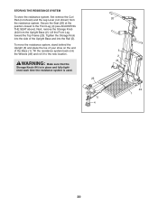
Tighten the Storage Knob into the Rail (5). STORING THE RESISTANCE SYSTEM To store the resistance system, first remove the Curl Pad (not shown) and the Leg Lever (not shown) from the Upright Base (2). Secure the Seat (25) at the position closest to the new location. Lift the Front Leg toward the Top Frame (20). To move the resistance system, stand behind the Upright (3) and place the toe of your shoe on the end of the Upright Base and into the side of the Base (1). WARNING: Make sure that the Storage Knob (44) is in place and fully tightened each time the resistance system is ...
Tighten the Storage Knob into the Rail (5). STORING THE RESISTANCE SYSTEM To store the resistance system, first remove the Curl Pad (not shown) and the Leg Lever (not shown) from the Upright Base (2). Secure the Seat (25) at the position closest to the new location. Lift the Front Leg toward the Top Frame (20). To move the resistance system, stand behind the Upright (3) and place the toe of your shoe on the end of the Upright Base and into the side of the Base (1). WARNING: Make sure that the Storage Knob (44) is in place and fully tightened each time the resistance system is ...