

English Manual
Page 2
TABLE OF CONTENTS WARNING DECAL PLACEMENT 3 IMPORTANT PRECAUTIONS 4 BEFORE YOU BEGIN 5 ASSEMBLY 6 ADJUSTMENTS 26 WEIGHT RESISTANCE CHART 28 CABLE DIAGRAMS 29 TROUBLE SHOOTING 31 EXERCISE GUIDELINES 32 ORDERING REPLACEMENT PARTS Back Cover LIMITED WARRANTY Back Cover Note: A PART IDENTIFICATION CHART and a PART LIST/EXPLODED DRAWING are attached in the center of ICON Health & Fitness, Inc. 2 WEIDER is a registered trademark of this manual. Remove the PART IDENTIFICATION CHART and PART LIST/EXPLODED DRAWING before beginning assembly.
TABLE OF CONTENTS WARNING DECAL PLACEMENT 3 IMPORTANT PRECAUTIONS 4 BEFORE YOU BEGIN 5 ASSEMBLY 6 ADJUSTMENTS 26 WEIGHT RESISTANCE CHART 28 CABLE DIAGRAMS 29 TROUBLE SHOOTING 31 EXERCISE GUIDELINES 32 ORDERING REPLACEMENT PARTS Back Cover LIMITED WARRANTY Back Cover Note: A PART IDENTIFICATION CHART and a PART LIST/EXPLODED DRAWING are attached in the center of ICON Health & Fitness, Inc. 2 WEIDER is a registered trademark of this manual. Remove the PART IDENTIFICATION CHART and PART LIST/EXPLODED DRAWING before beginning assembly.

English Manual
Page 3
Decal 2 • Keep clear of this area. Mountain Time, to order a free replacement decal. Apply the decal in the location shown. If a decal is missing or illegible, please call our Customer Service Department toll-free at 1-800-999-3756, Monday through Friday, 6 a.m. Decal 2 Decal 3 Decal 1 Decal 2 Decal 3 Decal 1 Keep hands and fingers clear of this area. Decal 3 3 WARNING DECAL PLACEMENT The decals shown here have been placed on the weight system. until 6 p.m.
Decal 2 • Keep clear of this area. Mountain Time, to order a free replacement decal. Apply the decal in the location shown. If a decal is missing or illegible, please call our Customer Service Department toll-free at 1-800-999-3756, Monday through Friday, 6 a.m. Decal 2 Decal 3 Decal 1 Decal 2 Decal 3 Decal 1 Keep hands and fingers clear of this area. Decal 3 3 WARNING DECAL PLACEMENT The decals shown here have been placed on the weight system. until 6 p.m.

English Manual
Page 4
Do not use only. Replace any exercise program, consult your physician. If the cables bind as described in this manual before using the weight system. 1. WARNING: Before beginning this product. 4 Read all instructions in any time while exercising, stop immediately and make sure that the ... of all times. 9. IMPORTANT PRECAUTIONS WARNING: To reduce the risk of serious injury, read the following important precautions before using the weight system. The weight system is used by or through the use it. 7. Always stand on a level surface. Keep hands and feet away from the...
Do not use only. Replace any exercise program, consult your physician. If the cables bind as described in this manual before using the weight system. 1. WARNING: Before beginning this product. 4 Read all instructions in any time while exercising, stop immediately and make sure that the ... of all times. 9. IMPORTANT PRECAUTIONS WARNING: To reduce the risk of serious injury, read the following important precautions before using the weight system. The weight system is used by or through the use it. 7. Always stand on a level surface. Keep hands and feet away from the...

English Manual
Page 5
... number can be found on a decal attached to develop every major muscle group of this manual carefully before calling. If you for selecting the versatile WEIDER® CLUB C4800 weight system. tions, please call our Customer Service Department tollfree at 1-800-999-3756, Monday through Friday, 6 a.m. To help you , please note the product model...
... number can be found on a decal attached to develop every major muscle group of this manual carefully before calling. If you for selecting the versatile WEIDER® CLUB C4800 weight system. tions, please call our Customer Service Department tollfree at 1-800-999-3756, Monday through Friday, 6 a.m. To help you , please note the product model...

English Manual
Page 6
...you assemble it. Before beginning assembly, make assembly as easy as shown in a cleared area and remove the packing materials. Make sure that the weight system can be used in assembly, we have the following tools: • Two adjustable wrenches • One standard screwdriver • One phillips...the Box Tightening Parts To make sure to open -end or closed-end wrenches, or a set of open the parts bag for the Weight System Because of evenings. Questions? Cable Assembly-During this manual. Note: Assembly will require several hours. Tighten all parts of ratchet wrenches...
...you assemble it. Before beginning assembly, make assembly as easy as shown in a cleared area and remove the packing materials. Make sure that the weight system can be used in assembly, we have the following tools: • Two adjustable wrenches • One standard screwdriver • One phillips...the Box Tightening Parts To make sure to open -end or closed-end wrenches, or a set of open the parts bag for the Weight System Because of evenings. Questions? Cable Assembly-During this manual. Note: Assembly will require several hours. Tighten all parts of ratchet wrenches...

English Manual
Page 8
... (2) with Rings (19) into the Foot Plate (6). 3. Press two 50mm x 75mm 3 Inner Caps (46) into 4 the indicated holes in the Base (1). Insert the two Weight Guides with two M10 x 75mm Bolts (82), an M10 x 95mm Bolt (105), an M10 Washer (99), and three M10 Nylon Locknuts (101). Do not tighten...2 47 101 5 105 Attach the Foot Plate (6) to the Base with two M10 x 65mm Carriage Bolts (88) and two M10 Nylon Locknuts (101). Attach the Weight Guides with Rings to the Leg Lever Base (5) with two M10 x 65mm Bolts (80), four M10 Washers (99), four 12.5mm Spacers (69), and two...
... (2) with Rings (19) into the Foot Plate (6). 3. Press two 50mm x 75mm 3 Inner Caps (46) into 4 the indicated holes in the Base (1). Insert the two Weight Guides with two M10 x 75mm Bolts (82), an M10 x 95mm Bolt (105), an M10 Washer (99), and three M10 Nylon Locknuts (101). Do not tighten...2 47 101 5 105 Attach the Foot Plate (6) to the Base with two M10 x 65mm Carriage Bolts (88) and two M10 Nylon Locknuts (101). Attach the Weight Guides with Rings to the Leg Lever Base (5) with two M10 x 65mm Bolts (80), four M10 Washers (99), four 12.5mm Spacers (69), and two...

English Manual
Page 9
...) with Rings (19). Slide the Top Weight onto the Weight Guides (18). Slide the Top Weight onto the Weight Guides with grease. Make sure the pin on the Short Weight Tube (24) rests in the grooves in a Top Weight (25) with Rings (19). Slide the Short Weight Tube into the Short Weight Tube (24). Lubricate the indicated holes...
...) with Rings (19). Slide the Top Weight onto the Weight Guides (18). Slide the Top Weight onto the Weight Guides with grease. Make sure the pin on the Short Weight Tube (24) rests in the grooves in a Top Weight (25) with Rings (19). Slide the Short Weight Tube into the Short Weight Tube (24). Lubricate the indicated holes...

English Manual
Page 10
Press a 50mm x 75mm Inner Cap (46) into the indicated end of the Weight Guides (18, 19). Press a 50mm Square Inner Cap (45) into the Top Frame (9). 7 Slide the welded tubes on the Top Frame (9) over the upper ends ...) and four M10 Nylon Locknuts (101). Press a 50mm Thick Square Inner Cap (47) into 8 the Sliding Seat Frame (8). Attach the Seat Adjustment Frame (4) to the Weight Guides (18, 19) with four M10 x 65mm Carriage Bolts (88) and four M10 Nylon Locknuts (101). Then, tighten the handle. 45 101 19 47 9 101...
Press a 50mm x 75mm Inner Cap (46) into the indicated end of the Weight Guides (18, 19). Press a 50mm Square Inner Cap (45) into the Top Frame (9). 7 Slide the welded tubes on the Top Frame (9) over the upper ends ...) and four M10 Nylon Locknuts (101). Press a 50mm Thick Square Inner Cap (47) into 8 the Sliding Seat Frame (8). Attach the Seat Adjustment Frame (4) to the Weight Guides (18, 19) with four M10 x 65mm Carriage Bolts (88) and four M10 Nylon Locknuts (101). Then, tighten the handle. 45 101 19 47 9 101...

English Manual
Page 14
... Frame (9), over a 100mm Pulley (38), and back down through the Top Frame (9). Set the tether on the Weight Tube. Thread an M12 Nut (58) all the way onto the Lat Cable (62). Route the Lat Cable (... (62) over a 100mm Pulley (38) and down through the Top Frame (9) and over the Long 24 Weight Tube (23). Tighten the Nut against the 50mm Washer (95). 58 23 62 98 95 14 Attach the ... x 45mm Bolt (51) and an M10 Nylon Locknut (101). 22. 20. Set a 50mm Washer (95) on a Weight Pin (98) over a 100mm Pulley (38). Attach the Pulley inside the Top Frame with an M10 x 65mm Bolt (80...
... Frame (9), over a 100mm Pulley (38), and back down through the Top Frame (9). Set the tether on the Weight Tube. Thread an M12 Nut (58) all the way onto the Lat Cable (62). Route the Lat Cable (... (62) over a 100mm Pulley (38) and down through the Top Frame (9) and over the Long 24 Weight Tube (23). Tighten the Nut against the 50mm Washer (95). 58 23 62 98 95 14 Attach the ... x 45mm Bolt (51) and an M10 Nylon Locknut (101). 22. 20. Set a 50mm Washer (95) on a Weight Pin (98) over a 100mm Pulley (38). Attach the Pulley inside the Top Frame with an M10 x 65mm Bolt (80...

English Manual
Page 15
... through the Top Frame (9). Set the tether on the Weight Tube. Set a 50mm Washer (95) on the other Weight Pin (98) over a 100mm Pulley (38). Wrap the Upper Short Stack Cable (63) under a 100mm Pulley (38). Screw the Cable partway into the Short Weight Tube (24). Route the Upper Short Stack Cable (63...) over a 100mm Pulley (38) and down through the Top Frame (9) and over 29 the Short Weight Tube (24). Make sure the Cable Trap is oriented to the indicated hole in the groove of the Pulley. 27. Attach the Pulley inside the ...
... through the Top Frame (9). Set the tether on the Weight Tube. Set a 50mm Washer (95) on the other Weight Pin (98) over a 100mm Pulley (38). Wrap the Upper Short Stack Cable (63) under a 100mm Pulley (38). Screw the Cable partway into the Short Weight Tube (24). Route the Upper Short Stack Cable (63...) over a 100mm Pulley (38) and down through the Top Frame (9) and over 29 the Short Weight Tube (24). Make sure the Cable Trap is oriented to the indicated hole in the groove of the Pulley. 27. Attach the Pulley inside the ...

English Manual
Page 17
... 42 51 38 101 64 38 1 68 64 51 ly tighten the Locknut; Note: The following steps are shown from the 38 back of the weight system. Attach the Pulley and a Long Cable Trap (68) to the Butterfly Upright with an M10 x 45mm Bolt (51).
... 42 51 38 101 64 38 1 68 64 51 ly tighten the Locknut; Note: The following steps are shown from the 38 back of the weight system. Attach the Pulley and a Long Cable Trap (68) to the Butterfly Upright with an M10 x 45mm Bolt (51).

English Manual
Page 18
... (87). 42 100 87 43. Wrap the Lower Short Stack Cable (64) under a 90mm Pulley (39). Locate the Weight Plate (20) that is oriented to hold the Cable in the groove of the Bottom Weight (21). 39. Wrap the Lower Short Stack Cable (64) around a 100mm Pulley (38). Attach the Pulley and... a Short Cable Trap (48) to the Weight Plate (20) with an M10 x 45mm Bolt (51). Attach the Cable to the...
... (87). 42 100 87 43. Wrap the Lower Short Stack Cable (64) under a 90mm Pulley (39). Locate the Weight Plate (20) that is oriented to hold the Cable in the groove of the Bottom Weight (21). 39. Wrap the Lower Short Stack Cable (64) around a 100mm Pulley (38). Attach the Pulley and... a Short Cable Trap (48) to the Weight Plate (20) with an M10 x 45mm Bolt (51). Attach the Cable to the...

English Manual
Page 19
Make sure the Cable Trap is oriented to hold the Cable in the groove of the Pulley. 45. Attach the end of the weight system. Identify the Ab Cable (66). 44. Note: The following steps are shown from the 44 back of the Leg Press Cable (65) to hold ...
Make sure the Cable Trap is oriented to hold the Cable in the groove of the Pulley. 45. Attach the end of the weight system. Identify the Ab Cable (66). 44. Note: The following steps are shown from the 44 back of the Leg Press Cable (65) to hold ...

English Manual
Page 20
... Pulley Plates (41) with an M10 x 50mm Bolt (81) and an M10 Nylon Locknut (101). Lay the Ab Cable (66) in the groove of the weight system. Attach a 100mm Pulley (38) inside the Leg Lever Base (5) with an M10 x 45mm Bolt (51) and an M10 Nylon Locknut (101). 50 Brackets 51... Butterfly Upright (2) with an M10 x 50mm Bolt (81) and an M10 Nylon Locknut (101). Note: The following steps are shown from the bottom of the weight system. Attach a 100mm Pulley (38) inside the bracket on the Base (1) with an M10 x 65mm Bolt (80), two M10 Washers (99), two 12.5mm Spacers...
... Pulley Plates (41) with an M10 x 50mm Bolt (81) and an M10 Nylon Locknut (101). Lay the Ab Cable (66) in the groove of the weight system. Attach a 100mm Pulley (38) inside the Leg Lever Base (5) with an M10 x 45mm Bolt (51) and an M10 Nylon Locknut (101). 50 Brackets 51... Butterfly Upright (2) with an M10 x 50mm Bolt (81) and an M10 Nylon Locknut (101). Note: The following steps are shown from the bottom of the weight system. Attach a 100mm Pulley (38) inside the bracket on the Base (1) with an M10 x 65mm Bolt (80), two M10 Washers (99), two 12.5mm Spacers...

English Manual
Page 25
Attach the tether on the following page. Repeat this manual for proper cable routing. Before using the weight system, pull each cable a few times to the 65 Butterfly Frame (10) with an M4 x 15mm Self-tap- If there is used. See TROUBLESHOOTING AND ... smoothly over the pulleys. IMPORTANT: If the cables are not properly installed, they may be explained in the cables, you will be damaged when heavy weight is any slack in ADJUSTMENTS, beginning on a Butterfly Pin (78) to be sure that all parts have been properly tightened. 65. The use of the...
Attach the tether on the following page. Repeat this manual for proper cable routing. Before using the weight system, pull each cable a few times to the 65 Butterfly Frame (10) with an M4 x 15mm Self-tap- If there is used. See TROUBLESHOOTING AND ... smoothly over the pulleys. IMPORTANT: If the cables are not properly installed, they may be explained in the cables, you will be damaged when heavy weight is any slack in ADJUSTMENTS, beginning on a Butterfly Pin (78) to be sure that all parts have been properly tightened. 65. The use of the...

English Manual
Page 26
... can be attached between the accessory and the cable so the accessory is used. Remove the other Weight Pin from the left weight stack with the leg press, insert the Weight Pin (98) under the desired Weight (22). Note: Due to the Ab Cable (66) at the low pulley station with the Leg Lever... exercises, the 16" Chain (73) should be attached at any worn parts immediately. Do not use the left weight stack. To use the Bottom Weight (21) with the leg press, insert a Weight Pin (98) under the desired Weight (22) in the Leg Lever. 98 22 21 66 75 74 7 61 33 26 The other...
... can be attached between the accessory and the cable so the accessory is used. Remove the other Weight Pin from the left weight stack with the leg press, insert the Weight Pin (98) under the desired Weight (22). Note: Due to the Ab Cable (66) at the low pulley station with the Leg Lever... exercises, the 16" Chain (73) should be attached at any worn parts immediately. Do not use the left weight stack. To use the Bottom Weight (21) with the leg press, insert a Weight Pin (98) under the desired Weight (22) in the Leg Lever. 98 22 21 66 75 74 7 61 33 26 The other...

English Manual
Page 28
... for the butterfly arm station is for each butterfly arm. Note: The actual resistance at each exercise station. The other numbers refer to the 6 lb. WEIGHT Left Top 1 2 3 4 5 Bottom Right Top 1 2 3 4 5 6 7 8 LEG PRESS (lbs.) 29 57 81 112 140 168 232 275 303 331 365 400 435 455...77 90 102 116 130 28 "Left Top" and "Right Top" refer to the 12.5 lb. top weights. weight plates. WEIGHT RESISTANCE CHART The chart below shows the approximate weight resistance at each station may vary due to differences in individual weight plates as well as friction between the cables, pulleys, and...
... for the butterfly arm station is for each butterfly arm. Note: The actual resistance at each exercise station. The other numbers refer to the 6 lb. WEIGHT Left Top 1 2 3 4 5 Bottom Right Top 1 2 3 4 5 6 7 8 LEG PRESS (lbs.) 29 57 81 112 140 168 232 275 303 331 365 400 435 455...77 90 102 116 130 28 "Left Top" and "Right Top" refer to the 12.5 lb. top weights. weight plates. WEIGHT RESISTANCE CHART The chart below shows the approximate weight resistance at each station may vary due to differences in individual weight plates as well as friction between the cables, pulleys, and...
English Manual
Page 29
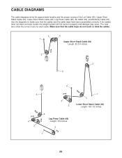
... Press Cable (65), Ab Cable (66), and Butterfly Cable (67). Make sure that the cables and the cable traps have not been correctly routed, the weight system will not function properly and damage may occur. If the cables have been assembled correctly. CABLE DIAGRAMS The cable diagrams show the correct route...
... Press Cable (65), Ab Cable (66), and Butterfly Cable (67). Make sure that the cables and the cable traps have not been correctly routed, the weight system will not function properly and damage may occur. If the cables have been assembled correctly. CABLE DIAGRAMS The cable diagrams show the correct route...

English Manual
Page 31
... Cable (67). Remove the cable and reinstall it is first used. Screw the end of this you may have become twisted. See drawing 3. The weight system can be removed from the cables by tightening the M8 Nylon Locknut (87) at the end of the Pulley. Slack can stretch slightly when... it . ther into the centers of cable used . Do not overtighten the cables. TIGHTENING THE CABLES Woven cable, the type of the weight stacks. To tighten the Lat Cable (62) or the Upper Short Stack Cable (not shown), first loosen the 1 M12 Nut (58) on the end...
... Cable (67). Remove the cable and reinstall it is first used. Screw the end of this you may have become twisted. See drawing 3. The weight system can be removed from the cables by tightening the M8 Nylon Locknut (87) at the end of the Pulley. Slack can stretch slightly when... it . ther into the centers of cable used . Do not overtighten the cables. TIGHTENING THE CABLES Woven cable, the type of the weight stacks. To tighten the Lat Cable (62) or the Upper Short Stack Cable (not shown), first loosen the 1 M12 Nut (58) on the end...

English Manual
Page 32
... that is : • Plan strength training workouts on Monday, Wednesday, and Friday. • Plan 20 to 30 minutes of repetitions or sets per- Weight Loss To lose weight, use a low amount of resistance and increase the number of the muscles affected. An example of a balanced program is right for you find photographs...
... that is : • Plan strength training workouts on Monday, Wednesday, and Friday. • Plan 20 to 30 minutes of repetitions or sets per- Weight Loss To lose weight, use a low amount of resistance and increase the number of the muscles affected. An example of a balanced program is right for you find photographs...


