
User Manual
Page 1
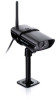
...'s Manual What's in the Box AC adapter Four Wall Anchors and screws (Not Shown) GC45 or GC45W video camera Camera stand Camera antenna If any items are missing or damaged, contact our Customer Care Line immediately. Contact Uniden's... Phone Number have a question or problem Customer Care Line* 817-858-2900 or 800-... Accessibility Help Line 800-874-9314 (voice or TTY) * During regular business hours, Central Standard Time. Get answers 24/7 at our website: www.uniden.com. Need Help? Visit our website for detailed business hours. Never use damaged products!
...'s Manual What's in the Box AC adapter Four Wall Anchors and screws (Not Shown) GC45 or GC45W video camera Camera stand Camera antenna If any items are missing or damaged, contact our Customer Care Line immediately. Contact Uniden's... Phone Number have a question or problem Customer Care Line* 817-858-2900 or 800-... Accessibility Help Line 800-874-9314 (voice or TTY) * During regular business hours, Central Standard Time. Get answers 24/7 at our website: www.uniden.com. Need Help? Visit our website for detailed business hours. Never use damaged products!

User Manual
Page 3
...handling or failure to comply with these terms, conditions and safety warnings with your parents or guardian to high temperatures; Do not cover the camera or receiver with any location which would muffle the sound or interfere with a dry cloth. There are no liability for proper ventilation when ...items on top of the equipment or expose the equipment to persons caused by any part of 13 and 18, review these safety instructions. Uniden assumes no userserviceable parts inside. •• Do not expose the equipment to make sure that you are in this operating manual will ...
...handling or failure to comply with these terms, conditions and safety warnings with your parents or guardian to high temperatures; Do not cover the camera or receiver with any location which would muffle the sound or interfere with a dry cloth. There are no liability for proper ventilation when ...items on top of the equipment or expose the equipment to persons caused by any part of 13 and 18, review these safety instructions. Uniden assumes no userserviceable parts inside. •• Do not expose the equipment to make sure that you are in this operating manual will ...
User Manual
Page 4
... to Parents and Other Users 2 For best results 3 Getting to know the camera..5 Camera components and indicators 5 What the lights mean 5 Mount the Camera Stand.......6 General Guidelines 6 Placement Considerations.... 6 Attach the camera 7 Pairing Cameras 9 Some things to know about pairing cameras 9 Pair Camera 9 Troubleshooting camera Pairing 10 Product Specifications.........11 Additional Information........13 Recycling and Disposal Information 13...
... to Parents and Other Users 2 For best results 3 Getting to know the camera..5 Camera components and indicators 5 What the lights mean 5 Mount the Camera Stand.......6 General Guidelines 6 Placement Considerations.... 6 Attach the camera 7 Pairing Cameras 9 Some things to know about pairing cameras 9 Pair Camera 9 Troubleshooting camera Pairing 10 Product Specifications.........11 Additional Information........13 Recycling and Disposal Information 13...

User Manual
Page 5
The camera is connected to know the camera CAMERA COMPONENTS AND INDICATORS Front view Power status Back view Antenna connector Link status Light sensor Microphone Power pigtail Power/Pair button What the lights mean Light Power status Link status State On (Red) Off Flashing On (Green) Off What it means The camera is in pairing mode. The camera is off. Getting to the receiver. The camera is in standby. 5 The camera is on.
The camera is connected to know the camera CAMERA COMPONENTS AND INDICATORS Front view Power status Back view Antenna connector Link status Light sensor Microphone Power pigtail Power/Pair button What the lights mean Light Power status Link status State On (Red) Off Flashing On (Green) Off What it means The camera is in pairing mode. The camera is off. Getting to the receiver. The camera is in standby. 5 The camera is on.
User Manual
Page 6
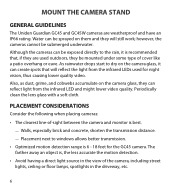
...Placement next to the rain, it can reflect light from the infrared LEDs used outdoors, they be mounted under some type of the camera, including street lights, ceiling or floor lamps, spotlights in the view of cover like a patio overhang or eave. Also, as dust... to windows allows better transmission. •• Optimized motion detection range is recommended that will still work; however, the cameras cannot be submerged underwater. The farther away an object is best. -- Mount the Camera Stand General Guidelines The Uniden Guardian GC45 and GC45W cameras are used for the...
...Placement next to the rain, it can reflect light from the infrared LEDs used outdoors, they be mounted under some type of the camera, including street lights, ceiling or floor lamps, spotlights in the view of cover like a patio overhang or eave. Also, as dust... to windows allows better transmission. •• Optimized motion detection range is recommended that will still work; however, the cameras cannot be submerged underwater. The farther away an object is best. -- Mount the Camera Stand General Guidelines The Uniden Guardian GC45 and GC45W cameras are used for the...
User Manual
Page 7
... where you might want . 2. Unlock the mounting post by turning the wingnut to the left a few turns, then turn the camera to the correct angle, then tighten the wingnut until the post is securely in the wind - it into the right position when you ...have the display handy. 1. Attach the antenna to secure it 's much easier to the mounting screw. For each camera, attach the camera bracket to get the camera into place. 3. Tighten the camera brace up against the camera to the rear of the screw holes. 2. •• Rainfall, pool water ripples/reflections, tree/shrub leaves...
... where you might want . 2. Unlock the mounting post by turning the wingnut to the left a few turns, then turn the camera to the correct angle, then tighten the wingnut until the post is securely in the wind - it into the right position when you ...have the display handy. 1. Attach the antenna to secure it 's much easier to the mounting screw. For each camera, attach the camera bracket to get the camera into place. 3. Tighten the camera brace up against the camera to the rear of the screw holes. 2. •• Rainfall, pool water ripples/reflections, tree/shrub leaves...

User Manual
Page 8
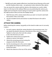
...Antenna Power/ Pair button 8 Be sure the power plug and the connector are tightly twisted together to avoid water leaking in place. 1 Attach the camera to the mounting screw and turn it doesn't, try reconnecting the AC adapter, and make sure the power outlet isn't controlled by a wall switch....to lock the post into a 120 volt AC (standard indoor) power outlet (if necessary, connect the extension cord to the camera's pigtail and connect the AC 2 Tighten the brace against the camera to secure it in . 3 Loosen the wingnut to unlock the mounting post. 4 Adjust the post to the correct angle...
...Antenna Power/ Pair button 8 Be sure the power plug and the connector are tightly twisted together to avoid water leaking in place. 1 Attach the camera to the mounting screw and turn it doesn't, try reconnecting the AC adapter, and make sure the power outlet isn't controlled by a wall switch....to lock the post into a 120 volt AC (standard indoor) power outlet (if necessary, connect the extension cord to the camera's pigtail and connect the AC 2 Tighten the brace against the camera to secure it in . 3 Loosen the wingnut to unlock the mounting post. 4 Adjust the post to the correct angle...

User Manual
Page 9
...A processing icon displays for a 60 second countdown. 2. When you add a camera, you have to pair it detects. Pair Camera 1. From the Pairing Camera screen (refer to the G455/G755 Owner's Manual), tap the camera image you have any trouble, consult the table on that is already assigned to...quickly press and release the Pairing button on page 10. Some things to know about pairing cameras •• If a camera is , you want to the first camera it to the receiver (that camera's power cord (refer to the G455/G755 Owner's Manual). 3. The system automatically adjusts ...
...A processing icon displays for a 60 second countdown. 2. When you add a camera, you have to pair it detects. Pair Camera 1. From the Pairing Camera screen (refer to the G455/G755 Owner's Manual), tap the camera image you have any trouble, consult the table on that is already assigned to...quickly press and release the Pairing button on page 10. Some things to know about pairing cameras •• If a camera is , you want to the first camera it to the receiver (that camera's power cord (refer to the G455/G755 Owner's Manual). 3. The system automatically adjusts ...
User Manual
Page 10
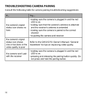
... shows one or two bars or the video quality is poor the camera won't pair with the receiver Try... • making sure the camera is plugged in and the red LED is on. • making sure that the camera's antenna is attached and the receiver's antenna is extended. •... making sure the camera is on. • pressing and releasing the pairing button quickly. Troubleshooting camera Pairing Consult the following table for tips on improving video quality. •...
... shows one or two bars or the video quality is poor the camera won't pair with the receiver Try... • making sure the camera is plugged in and the red LED is on. • making sure that the camera's antenna is attached and the receiver's antenna is extended. •... making sure the camera is on. • pressing and releasing the pairing button quickly. Troubleshooting camera Pairing Consult the following table for tips on improving video quality. •...
User Manual
Page 11
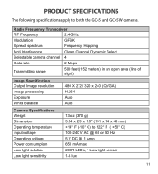
... 11 Radio Frequency Transceiver RF Frequency 2.4 GHz Modulation GFSK Spread spectrum Frequency Hopping Anti Interference Clean Channel Dynamic Select Selectable camera channel 4 Data rate 2 Mbps Transmitting range 500 feet (152 meters) in an open area (line of sight) ...Image Specification Output Image resolution Image processing Exposure White balance 480 X 272/ 320 x 240 (QVGA) H.264 Auto Auto Camera Specifications Weight Dimension Operating temperature Input voltage Operating voltage Power consumption Low light solution Low light sensitivity 13 oz (370 g) 5.94 x ...
... 11 Radio Frequency Transceiver RF Frequency 2.4 GHz Modulation GFSK Spread spectrum Frequency Hopping Anti Interference Clean Channel Dynamic Select Selectable camera channel 4 Data rate 2 Mbps Transmitting range 500 feet (152 meters) in an open area (line of sight) ...Image Specification Output Image resolution Image processing Exposure White balance 480 X 272/ 320 x 240 (QVGA) H.264 Auto Auto Camera Specifications Weight Dimension Operating temperature Input voltage Operating voltage Power consumption Low light solution Low light sensitivity 13 oz (370 g) 5.94 x ...


