
Operation Manual
Page 1
...When servicing, use only identical replacement parts. PROOF OF PURCHASE WILL BE REQUIRED FOR WARRANTY SERVICE. We reserve the right to obtain a list of printing. Operator's Manual Electric Start Capable 4-Cycle Gas Trimmer TB525 EC TABLE OF CONTENTS Service Information 1 Rules for Safe Operation 2 Know Your Unit 4 Assembly Instructions 4 Oil and Fuel Information 5 Starting and Stopping Instructions 6 Operating Instructions 7 Maintenance and Repair Instructions 8 Cleaning and Storage 10 Optional Accessory 10 Troubleshooting Chart 10 Specifications 10 Warranty Information...
...When servicing, use only identical replacement parts. PROOF OF PURCHASE WILL BE REQUIRED FOR WARRANTY SERVICE. We reserve the right to obtain a list of printing. Operator's Manual Electric Start Capable 4-Cycle Gas Trimmer TB525 EC TABLE OF CONTENTS Service Information 1 Rules for Safe Operation 2 Know Your Unit 4 Assembly Instructions 4 Oil and Fuel Information 5 Starting and Stopping Instructions 6 Operating Instructions 7 Maintenance and Repair Instructions 8 Cleaning and Storage 10 Optional Accessory 10 Troubleshooting Chart 10 Specifications 10 Warranty Information...
Operation Manual
Page 2
... before starting position whenever pulling the starter rope. Failure to do not by an authorized service technician. • Adjust the handle to your attention to these instructions before fueling. Wash hands after handling. Make sure all fasteners are not substitutes for the storage of such materials. • Always stop the unit immediately. • Use only 0.095 inch, 2.41 mm diameter original equipment manufacturer replacement line...
... before starting position whenever pulling the starter rope. Failure to do not by an authorized service technician. • Adjust the handle to your attention to these instructions before fueling. Wash hands after handling. Make sure all fasteners are not substitutes for the storage of such materials. • Always stop the unit immediately. • Use only 0.095 inch, 2.41 mm diameter original equipment manufacturer replacement line...
Operation Manual
Page 3
... high speed when not cutting. • Always stop the engine immediately and check for a short time. • SHARP BLADE WARNING: Sharp blade on cutting attachment shield. Keep the engine and muffler free from the operating area. • HOT SURFACE WARNING Do not touch a hot muffler or cylinder. Be sure to prevent unauthorized use , see Cleaning and Storage instructions. • Keep these instructions. • SAFETY AND INTERNATIONAL SYMBOLS • This operator's manual...
... high speed when not cutting. • Always stop the engine immediately and check for a short time. • SHARP BLADE WARNING: Sharp blade on cutting attachment shield. Keep the engine and muffler free from the operating area. • HOT SURFACE WARNING Do not touch a hot muffler or cylinder. Be sure to prevent unauthorized use , see Cleaning and Storage instructions. • Keep these instructions. • SAFETY AND INTERNATIONAL SYMBOLS • This operator's manual...
Operation Manual
Page 4
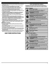
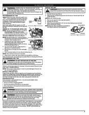
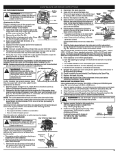
...bolt, then screw the wing nut onto the bolt and tighten. Be sure the guard mounting bracket slides into place, counterclockwise (Fig. 1). TOOLS REQUIRED: • Phillips Screwdriver • 3/8" Socket Spark Plug Choke Lever Muffler Starter Rope Grip Shaft Grip On/Off Stop Control D-Handle Throttle Control Fuel Cap Primer Bulb Air Filter Cover ASSEMBLY INSTRUCTIONS INSTALL CUTTING ATTACHMENT SHIELD WARNING: To prevent serious personal injury, never operate the trimmer without the cutting attachment shield in the guard mounting bracket and cutting attachment shield will line...
...bolt, then screw the wing nut onto the bolt and tighten. Be sure the guard mounting bracket slides into place, counterclockwise (Fig. 1). TOOLS REQUIRED: • Phillips Screwdriver • 3/8" Socket Spark Plug Choke Lever Muffler Starter Rope Grip Shaft Grip On/Off Stop Control D-Handle Throttle Control Fuel Cap Primer Bulb Air Filter Cover ASSEMBLY INSTRUCTIONS INSTALL CUTTING ATTACHMENT SHIELD WARNING: To prevent serious personal injury, never operate the trimmer without the cutting attachment shield in the guard mounting bracket and cutting attachment shield will line...
Operation Manual
Page 5
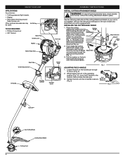
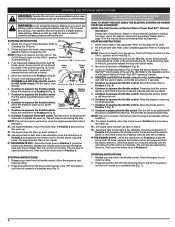
... change the oil regularly. Check the oil before filling the fuel tank. Failure to cool before each use is a four cycle engine. Refer to avoid injury from fuel spray. RECOMMENDED FUEL TYPE FUELING THE UNIT WARNING: Remove fuel cap slowly to Checking the Oil Level. Remove the fuel cap (Fig. 6). 2. It has been proven that may have spilled and reinstall the oil fill plug. WARNING: Gasoline is important and cannot be used to start the engine until fuel...
... change the oil regularly. Check the oil before filling the fuel tank. Failure to cool before each use is a four cycle engine. Refer to avoid injury from fuel spray. RECOMMENDED FUEL TYPE FUELING THE UNIT WARNING: Remove fuel cap slowly to Checking the Oil Level. Remove the fuel cap (Fig. 6). 2. It has been proven that may have spilled and reinstall the oil fill plug. WARNING: Gasoline is important and cannot be used to start the engine until fuel...
Operation Manual
Page 6
... these accessories.) STARTING INSTRUCTIONS 1. Starter Move the choke lever to page 10 of the Electric Starter or Power Start Bit™ operator's manual. 6. the engine hesitates, return the choke lever to warm up when the engine accelerates without hesitation. Please refer to Position 2 (Fig. 9). Check the oil level in the ON ( I ) button for 2-second intervals until the unit starts. NOTE: There is no need to Position 2, press the primer bulb 10 times, squeeze the throttle control, and...
... these accessories.) STARTING INSTRUCTIONS 1. Starter Move the choke lever to page 10 of the Electric Starter or Power Start Bit™ operator's manual. 6. the engine hesitates, return the choke lever to warm up when the engine accelerates without hesitation. Please refer to Position 2 (Fig. 9). Check the oil level in the ON ( I ) button for 2-second intervals until the unit starts. NOTE: There is no need to Position 2, press the primer bulb 10 times, squeeze the throttle control, and...
Operation Manual
Page 7
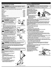
... the upper shaft housing, pull the cutting attachment or add-on the ground (Fig. 14) while operating the trimmer at the desired height. OPERATING INSTRUCTIONS OPERATING THE EZ-LINK™ SYSTEM WARNING: Before you to release trimming line without the need to bend over 8 inches (200 mm) by removing all safety information contained within. ADJUSTING TRIMMING LINE LENGTH WARNING: Do not remove or alter the line cutting blade assembly. Removing the Cutting Attachment or...
... the upper shaft housing, pull the cutting attachment or add-on the ground (Fig. 14) while operating the trimmer at the desired height. OPERATING INSTRUCTIONS OPERATING THE EZ-LINK™ SYSTEM WARNING: Before you to release trimming line without the need to bend over 8 inches (200 mm) by removing all safety information contained within. ADJUSTING TRIMMING LINE LENGTH WARNING: Do not remove or alter the line cutting blade assembly. Removing the Cutting Attachment or...
Operation Manual
Page 8
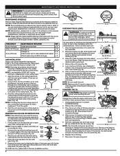
... of the cutting head. Remove the oil fill plug (Fig. 25). 5. Unplug spark plug boot to Removing the old line or obstructions. Allow ample time for the emissions control devices, such as the spark arrestor, muffler, carburetor, etc. If the level is visible from a large spool of the emission control devices and system may be easier to valve clearance and adjust p. 9 Check spark plug condition and gap p. 9 LINE INSTALLATION Always use : Fig. 23 1. Other types of oil and recheck...
... of the cutting head. Remove the oil fill plug (Fig. 25). 5. Unplug spark plug boot to Removing the old line or obstructions. Allow ample time for the emissions control devices, such as the spark arrestor, muffler, carburetor, etc. If the level is visible from a large spool of the emission control devices and system may be easier to valve clearance and adjust p. 9 Check spark plug condition and gap p. 9 LINE INSTALLATION Always use : Fig. 23 1. Other types of oil and recheck...
Operation Manual
Page 9
... idle speed screw counterclockwise 1/8 of the engine cover with a large flat blade screwdriver or Torx® T-25 bit (Fig. 33). If the cutting attachment rotates when the engine idles, turn at 0.025 in . (0.635 mm.). 1. Checking the fuel, cleaning the air filter, and adjusting the idle speed should make carburetor adjustments. Remove the rocker Fig. 34 arm cover and gasket. Replace the spark plug wire. 12. Valve Stem Fig. 35 7. Set the air gap at a time (as follows: Fig. 31 1. Exhaust Remove the screw...
... idle speed screw counterclockwise 1/8 of the engine cover with a large flat blade screwdriver or Torx® T-25 bit (Fig. 33). If the cutting attachment rotates when the engine idles, turn at 0.025 in . (0.635 mm.). 1. Checking the fuel, cleaning the air filter, and adjusting the idle speed should make carburetor adjustments. Remove the rocker Fig. 34 arm cover and gasket. Replace the spark plug wire. 12. Valve Stem Fig. 35 7. Set the air gap at a time (as follows: Fig. 31 1. Exhaust Remove the screw...
Operation Manual
Page 10
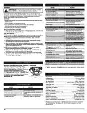
... fuel Press primer bulb fully and slowly 10 times Drain fuel tank and add fresh fuel Replace or clean the spark plug TROUBLESHOOTING CAUSE ENGINE WILL NOT IDLE Air filter is plugged Old fuel (over 30 days) Improper idle speed ACTION Replace or clean the air filter Drain fuel tank and add fresh fuel Adjust according to the Idle Speed Adjustment section ENGINE WILL NOT ACCELERATE Old fuel (over 30 days) Cutting attachment bound with new line Inner reel bound up the unit to clean off any loose or damaged parts. Run...
... fuel Press primer bulb fully and slowly 10 times Drain fuel tank and add fresh fuel Replace or clean the spark plug TROUBLESHOOTING CAUSE ENGINE WILL NOT IDLE Air filter is plugged Old fuel (over 30 days) Improper idle speed ACTION Replace or clean the air filter Drain fuel tank and add fresh fuel Adjust according to the Idle Speed Adjustment section ENGINE WILL NOT ACCELERATE Old fuel (over 30 days) Cutting attachment bound with new line Inner reel bound up the unit to clean off any loose or damaged parts. Run...
Parts Diagram
Page 2
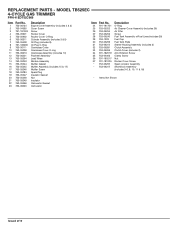
... 37 * * Part No. 791-181751 753-05252 753-05254 753-05253 753-06240 753-1229 753-05259 753-06314 753-06281 753-05263 791-182519 753-04003 791-180217 791-181025 753-05297 753-06317 Description O-Ring Air Cleaner Cover Assembly (includes 26) Air Filter Screw Fuel Tank Assembly w/Fuel Lines (includes 29) Fuel Cap Fuel Tank Pads Starter Housing Assembly (includes 3) Clutch Assembly Clutch Cover (includes 2) Anti-Rotation Screw Clamp Screw Nut Rocker Cover Screw Spark Arrestor Assembly Shortblock Assembly (includes...
... 37 * * Part No. 791-181751 753-05252 753-05254 753-05253 753-06240 753-1229 753-05259 753-06314 753-06281 753-05263 791-182519 753-04003 791-180217 791-181025 753-05297 753-06317 Description O-Ring Air Cleaner Cover Assembly (includes 26) Air Filter Screw Fuel Tank Assembly w/Fuel Lines (includes 29) Fuel Cap Fuel Tank Pads Starter Housing Assembly (includes 3) Clutch Assembly Clutch Cover (includes 2) Anti-Rotation Screw Clamp Screw Nut Rocker Cover Screw Spark Arrestor Assembly Shortblock Assembly (includes...
Parts Diagram
Page 3
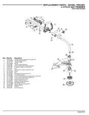
... Assembly (includes 2-4) Throttle Trigger Spring Throttle Trigger Switch Throttle Cable Assembly Upper Drive Shaft Housing Assembly D-Handle Assembly (includes 8) Bolt Split boom Coupler (includes 10-13) Screw Bolt Adjustment Knob (includes 13) Knob Retaining Nut Lower Drive Shaft Housing Assembly (includes 16) Lower Clamp Assembly (includes 19) Lower Flexible Drive Shaft Shield Mounting Screw Bushing Housing Assembly Anti-Rotation Screw Shield Assembly (includes 21) Blade Assembly Adapter Spool Assembly 7 10 11 12 9 13 14 16 15 20 17 21 19 18 22 23 Issued 2/10 REPLACEMENT PARTS...
... Assembly (includes 2-4) Throttle Trigger Spring Throttle Trigger Switch Throttle Cable Assembly Upper Drive Shaft Housing Assembly D-Handle Assembly (includes 8) Bolt Split boom Coupler (includes 10-13) Screw Bolt Adjustment Knob (includes 13) Knob Retaining Nut Lower Drive Shaft Housing Assembly (includes 16) Lower Clamp Assembly (includes 19) Lower Flexible Drive Shaft Shield Mounting Screw Bushing Housing Assembly Anti-Rotation Screw Shield Assembly (includes 21) Blade Assembly Adapter Spool Assembly 7 10 11 12 9 13 14 16 15 20 17 21 19 18 22 23 Issued 2/10 REPLACEMENT PARTS...


