Operation Manual
Page 2
.... Wear a face or dust mask if the operation is hot. Check with the controls and proper use . If it returns automatically to the head, hands and feet. • Clear the area of fire, electric shock and personal injury. The safety warnings do so can result in injury ...starting the engine. May be used in conjunction with a spark arrestor. Please keep these requirements. At a minimum, keep proper footing and balance. Never remove the fuel tank cap or add fuel when the engine is dusty. • Wear heavy long pants, boots, gloves and a long sleeve shirt. ...
.... Wear a face or dust mask if the operation is hot. Check with the controls and proper use . If it returns automatically to the head, hands and feet. • Clear the area of fire, electric shock and personal injury. The safety warnings do so can result in injury ...starting the engine. May be used in conjunction with a spark arrestor. Please keep these requirements. At a minimum, keep proper footing and balance. Never remove the fuel tank cap or add fuel when the engine is dusty. • Wear heavy long pants, boots, gloves and a long sleeve shirt. ...
Operation Manual
Page 7
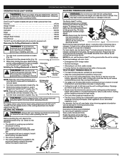
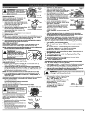
...use of the EZ-Link™ coupler (Fig. 11). Fig. 14 Each time the head is attempted in the operating position (Fig. 13). NOTE: Do not rest the Bump Head™ on installation or removal easier. 90˚ Edging Hole (Trimmer Only) 1. Allow the tip of trimming line ...attachment allows you begin using the line head cutting attachment with EZ-Link™ models), lock the release button of the cutting area at high speed. DECORATIVE TRIMMING Decorative trimming is parallel to do the cutting, especially along walls. Removing the Cutting Attachment or Add-On WARNING...
...use of the EZ-Link™ coupler (Fig. 11). Fig. 14 Each time the head is attempted in the operating position (Fig. 13). NOTE: Do not rest the Bump Head™ on installation or removal easier. 90˚ Edging Hole (Trimmer Only) 1. Allow the tip of trimming line ...attachment allows you begin using the line head cutting attachment with EZ-Link™ models), lock the release button of the cutting area at high speed. DECORATIVE TRIMMING Decorative trimming is parallel to do the cutting, especially along walls. Removing the Cutting Attachment or Add-On WARNING...
Operation Manual
Page 8
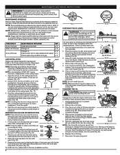
... are on a flat, level surface with the unit for a complete listing of terms and coverage for complete drainage. Arrow Cutting Head Knob Fig. 16 1. Remove the oil fill plug (Fig. 25). 5. Repeat this procedure until the desired cutting length is protruding from the outer spool. ...the emissions control devices, such as the spark arrestor, muffler, carburetor, etc. NOTE: Line installation DOES NOT require removal or disassembly of the cutting head. MAINTENANCE AND REPAIR INSTRUCTIONS WARNING: To prevent serious injury, never perform maintenance or repairs with the tab lock windows ...
... are on a flat, level surface with the unit for a complete listing of terms and coverage for complete drainage. Arrow Cutting Head Knob Fig. 16 1. Remove the oil fill plug (Fig. 25). 5. Repeat this procedure until the desired cutting length is protruding from the outer spool. ...the emissions control devices, such as the spark arrestor, muffler, carburetor, etc. NOTE: Line installation DOES NOT require removal or disassembly of the cutting head. MAINTENANCE AND REPAIR INSTRUCTIONS WARNING: To prevent serious injury, never perform maintenance or repairs with the tab lock windows ...
Operation Manual
Page 9
... rotate when the engine idles. 3. WARNING: The cutting attachment may spin during idle speed adjustments. Turn the idle speed screw in . Remove the spark plug from the cylinder head by turning a 5/8 in , clockwise, 1/8 of the back plate (Fig. 29). 8. Measure both intake and exhaust is operated without....•lb. (12.3-13.5 N•m) Do not over tighten. 0.025 in . (0.635 mm.) using a new gasket. Remove the spark plug from the cylinder head by an authorized service dealer. Replace cracked, fouled or dirty spark plug. Then pull the Tabs air filter cover out and up...
... rotate when the engine idles. 3. WARNING: The cutting attachment may spin during idle speed adjustments. Turn the idle speed screw in . Remove the spark plug from the cylinder head by turning a 5/8 in , clockwise, 1/8 of the back plate (Fig. 29). 8. Measure both intake and exhaust is operated without....•lb. (12.3-13.5 N•m) Do not over tighten. 0.025 in . (0.635 mm.) using a new gasket. Remove the spark plug from the cylinder head by an authorized service dealer. Replace cracked, fouled or dirty spark plug. Then pull the Tabs air filter cover out and up...
Operation Manual
Page 10
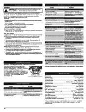
...• Allow the engine to cool before storing. • Lock up Replace the inner reel Cutting head dirty Clean inner reel and outer spool Line welded Line twisted when refilled Not enough line is exposed Disassemble, remove the welded section and rewind Disassemble and rewind the line Push the bump... head and pull out line until 4 inches (102 mm) of line is outside of the oil from the ...
...• Allow the engine to cool before storing. • Lock up Replace the inner reel Cutting head dirty Clean inner reel and outer spool Line welded Line twisted when refilled Not enough line is exposed Disassemble, remove the welded section and rewind Disassemble and rewind the line Push the bump... head and pull out line until 4 inches (102 mm) of line is outside of the oil from the ...


