
User's Guide for Satellite M500 Series
Page 58
...'s power on the base of the computer. You can be hot. Slot B is in Sleep or Hibernation mode, data will need a small Phillips screwdriver for this model Slot A is the bottom slot. 58 Getting Started Adding memory (optional) Installing a memory module Memory modules can install one memory module is to room temperature before they have cooled. Allow the module(s) to cool to be installed, it . If you install or remove a memory module, turn off the computer using the Start menu...
...'s power on the base of the computer. You can be hot. Slot B is in Sleep or Hibernation mode, data will need a small Phillips screwdriver for this model Slot A is the bottom slot. 58 Getting Started Adding memory (optional) Installing a memory module Memory modules can install one memory module is to room temperature before they have cooled. Allow the module(s) to cool to be installed, it . If you install or remove a memory module, turn off the computer using the Start menu...

User's Guide for Satellite M500 Series
Page 63
... computer to remove a memory module with the computer turned on. Getting Started Adding memory (optional) 63 14 Replace the memory module slot cover and secure it correctly as described in "Checking total memory" on page 65. In either of the above cases, the Sleep configuration will be saved. You can verify that the computer has recognized it using the screws. 15 Re-insert the main battery. Do...
... computer to remove a memory module with the computer turned on. Getting Started Adding memory (optional) 63 14 Replace the memory module slot cover and secure it correctly as described in "Checking total memory" on page 65. In either of the above cases, the Sleep configuration will be saved. You can verify that the computer has recognized it using the screws. 15 Re-insert the main battery. Do...

User's Guide for Satellite M500 Series
Page 65
... heading under Memory (RAM). For more information on inserting the main battery, see "Inserting a charged battery" on page 58), To do this: 1 Click Start, Control Panel, System and Maintenance, and then System. If the computer does not recognize the memory configuration, turn off the computer and remove the memory module slot cover (complete steps 1-8 in "Installing a memory module" on page 131. 6 Turn the computer right side up. 7 Reconnect the cables. 8 Restart the...
... heading under Memory (RAM). For more information on inserting the main battery, see "Inserting a charged battery" on page 58), To do this: 1 Click Start, Control Panel, System and Maintenance, and then System. If the computer does not recognize the memory configuration, turn off the computer and remove the memory module slot cover (complete steps 1-8 in "Installing a memory module" on page 131. 6 Turn the computer right side up. 7 Reconnect the cables. 8 Restart the...

User's Guide for Satellite M500 Series
Page 82
... can allow you need to install new software. 2 Connect the monitor's video cable to the RGB (monitor) port on the side of its capabilities which allows devices to work together over an HDMI cable. For more detailed HDMI-CEC information visit pcsupport.toshiba.com. 82 Getting Started Using external display devices Connecting to a TV using the Fn+F5 key. ❖ Switch the video output (HDMI or LCD) when executing certain desktop icons. ❖ Enable/Disable the HDMI-CEC function on the computer...
... can allow you need to install new software. 2 Connect the monitor's video cable to the RGB (monitor) port on the side of its capabilities which allows devices to work together over an HDMI cable. For more detailed HDMI-CEC information visit pcsupport.toshiba.com. 82 Getting Started Using external display devices Connecting to a TV using the Fn+F5 key. ❖ Switch the video output (HDMI or LCD) when executing certain desktop icons. ❖ Enable/Disable the HDMI-CEC function on the computer...
User's Guide for Satellite M500 Series
Page 161
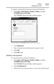
...power-on password function: 1 Click Start, All Programs, Toshiba, Utilities, and then TOSHIBA Password Utility. Deleting a user password To cancel the power-on password functions: 1 Click Start, All Programs, Toshiba, Utilities, and then TOSHIBA Password Utility. The TOSHIBA Password Utility window appears. (Sample Image) TOSHIBA Password Utility window 2 Click Registered. 3 Enter your password, and then enter it again to verify. 4 Click OK. 5 Click OK to remove the user password. The TOSHIBA Password Utility window appears. 2 Click Not Registered. 3 Follow the on-screen instructions...
...power-on password function: 1 Click Start, All Programs, Toshiba, Utilities, and then TOSHIBA Password Utility. Deleting a user password To cancel the power-on password functions: 1 Click Start, All Programs, Toshiba, Utilities, and then TOSHIBA Password Utility. The TOSHIBA Password Utility window appears. (Sample Image) TOSHIBA Password Utility window 2 Click Registered. 3 Enter your password, and then enter it again to verify. 4 Click OK. 5 Click OK to remove the user password. The TOSHIBA Password Utility window appears. 2 Click Not Registered. 3 Follow the on-screen instructions...
User's Guide for Satellite M500 Series
Page 182
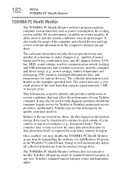
... collected information includes device operation time and number of actuations or status changes (e.g.: number of power button and Fn key combination uses, and AC adaptor, battery, LCD, fan, HDD, sound volume, wireless communication switch, docking and USB information), date of your Toshiba computer. Subject to the use restrictions above, the data logged on the computer's internal storage drive. Once enabled, you may use , and also computer and device usage (e.g.: power settings, battery temperature and recharging, CPU, memory, backlight illumination time...
... collected information includes device operation time and number of actuations or status changes (e.g.: number of power button and Fn key combination uses, and AC adaptor, battery, LCD, fan, HDD, sound volume, wireless communication switch, docking and USB information), date of your Toshiba computer. Subject to the use restrictions above, the data logged on the computer's internal storage drive. Once enabled, you may use , and also computer and device usage (e.g.: power settings, battery temperature and recharging, CPU, memory, backlight illumination time...
User's Guide for Satellite M500 Series
Page 193
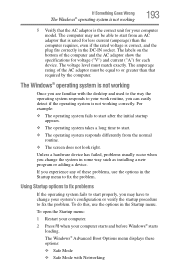
... fix problems If the operating system fails to start properly, you may not be equal to your work routine, you are familiar with Networking To do this, use the options in the Startup menu to change the system in the Startup menu. The amperage rating of the computer and the AC adaptor show the specifications for voltage ("V") and current ("A") for each device. The Windows® Advanced Boot Options menu displays...
... fix problems If the operating system fails to start properly, you may not be equal to your work routine, you are familiar with Networking To do this, use the options in the Startup menu to change the system in the Startup menu. The amperage rating of the computer and the AC adaptor show the specifications for voltage ("V") and current ("A") for each device. The Windows® Advanced Boot Options menu displays...

User's Guide for Satellite M500 Series
Page 197
... memory module installed, the error is worthwhile checking for the error again. This tab also provides options for the computer to work. For more information about Device Manager, refer to Windows® online Help. If Something Goes Wrong Resolving a hardware conflict 197 ❖ The Resources tab, which lists resources assigned to the monitor, optional external optical drive, optional external diskette drive, and other power-using resources. ❖ The Driver tab, which displays the drivers...
... memory module installed, the error is worthwhile checking for the error again. This tab also provides options for the computer to work. For more information about Device Manager, refer to Windows® online Help. If Something Goes Wrong Resolving a hardware conflict 197 ❖ The Resources tab, which lists resources assigned to the monitor, optional external optical drive, optional external diskette drive, and other power-using resources. ❖ The Driver tab, which displays the drivers...

User's Guide for Satellite M500 Series
Page 200
... adjusting the contrast and brightness controls on . The screen reactivates and allows you have plugged the external keyboard in the lower-right part of the Start menu. If you are using the built-in screen. If this , press Fn and F5 simultaneously (once). HINT: Holding the Fn key and pressing the F5 key several times will restart and recognize the device. Display problems Here are using an external monitor...
... adjusting the contrast and brightness controls on . The screen reactivates and allows you have plugged the external keyboard in the lower-right part of the Start menu. If you are using the built-in screen. If this , press Fn and F5 simultaneously (once). HINT: Holding the Fn key and pressing the F5 key several times will restart and recognize the device. Display problems Here are using an external monitor...

User's Guide for Satellite M500 Series
Page 252
... Disk Defragmenter 203 disk drive corrupted/damaged data files 203 missing files/trouble accessing a drive 202 running slow 203 display does not look normal/flickers 201 external monitor not working 201 display device connecting 81 external 81 display output settings 83 display panel opening 54 display problems screen is blank 200 display, external adjusting 84 disposal information 33 disposing of used batteries 133 double-click 80 DVD using 109 DVD player general problems 210 DVD-ROM or multi-function drive inserting discs 112 removing 112 E eject button optical drive...
... Disk Defragmenter 203 disk drive corrupted/damaged data files 203 missing files/trouble accessing a drive 202 running slow 203 display does not look normal/flickers 201 external monitor not working 201 display device connecting 81 external 81 display output settings 83 display panel opening 54 display problems screen is blank 200 display, external adjusting 84 disposal information 33 disposing of used batteries 133 double-click 80 DVD using 109 DVD player general problems 210 DVD-ROM or multi-function drive inserting discs 112 removing 112 E eject button optical drive...

User's Guide for Satellite M500 Series
Page 253
... HDMI™ Out Port 81 headphones using 145 Help and Support Windows® operating system 195 Hibernation mode 86 configuring 90 hot key 229 starting again from 92 hot key backlight 235 disabling or enabling TouchPad™ 233 disabling or enabling wireless devices 232 display brightness 231 Hibernation mode 229 keyboard overlays 235 Lock (Instant security) 226 Output (Display switch) 230 power plan 227 Sleep mode 228 volume mute 225 Zoom (Display resolution) 234 zooming in 235 zooming out 235 Hot Key Cards 220 Hot key functions 224 hot key power...
... HDMI™ Out Port 81 headphones using 145 Help and Support Windows® operating system 195 Hibernation mode 86 configuring 90 hot key 229 starting again from 92 hot key backlight 235 disabling or enabling TouchPad™ 233 disabling or enabling wireless devices 232 display brightness 231 Hibernation mode 229 keyboard overlays 235 Lock (Instant security) 226 Output (Display switch) 230 power plan 227 Sleep mode 228 volume mute 225 Zoom (Display resolution) 234 zooming in 235 zooming out 235 Hot Key Cards 220 Hot key functions 224 hot key power...

User's Guide for Satellite M500 Series
Page 254
... Internet Service Providers ISPs 142 J jack RJ-11 141 K keyboard character keys 100 function keys 101 hot keys 235 not working 191 overlay keys 102 special Windows® keys 101 troubleshooting 199 unexpected characters 199 using 100 keyboard, external 84 keyboard, full-size 100 L light AC power 51 drive in-use indicator 110, 113 lock computer, using 96 M main battery changing 129 installing 129, 131 removing 129 safety precautions 132 manual eject hole optical drive 110, 113 memory adding 57 problem solving 197 removing memory module slot cover...
... Internet Service Providers ISPs 142 J jack RJ-11 141 K keyboard character keys 100 function keys 101 hot keys 235 not working 191 overlay keys 102 special Windows® keys 101 troubleshooting 199 unexpected characters 199 using 100 keyboard, external 84 keyboard, full-size 100 L light AC power 51 drive in-use indicator 110, 113 lock computer, using 96 M main battery changing 129 installing 129, 131 removing 129 safety precautions 132 manual eject hole optical drive 110, 113 memory adding 57 problem solving 197 removing memory module slot cover...
User's Guide for Satellite M500 Series
Page 257
... TOSHIBA PC Health Monitor 182 TOSHIBA SD™ Memory Card Format Utility 165 TOSHIBA Service Station 180 TOSHIBA Zooming Utility 172 TouchPad™ control buttons 80 ON/OFF button 80 primary button 80 secondary button 80 using 79 traveling tips 135 troubleshooting DVD player general problems 210 external keyboard 199 keyboard 199 optical drive 203 turning on the computer 55 turning on the power 55 U USB Sleep and Charge cannot use 216 USB Sleep and Charge Utility 169 USB Wakeup function does not work 216 USB-compatible printer 84 user password, disabling 161 user password, setting...
... TOSHIBA PC Health Monitor 182 TOSHIBA SD™ Memory Card Format Utility 165 TOSHIBA Service Station 180 TOSHIBA Zooming Utility 172 TouchPad™ control buttons 80 ON/OFF button 80 primary button 80 secondary button 80 using 79 traveling tips 135 troubleshooting DVD player general problems 210 external keyboard 199 keyboard 199 optical drive 203 turning on the computer 55 turning on the power 55 U USB Sleep and Charge cannot use 216 USB Sleep and Charge Utility 169 USB Wakeup function does not work 216 USB-compatible printer 84 user password, disabling 161 user password, setting...

Maintenance Manual
Page 3
... battery to perform hardware service maintenance for the Toshiba Personal Computer PORTÉGÉ M500. Improper repair of the computer may result in property damage, if the safety instruction is not fully fastened, it could come loose, creating a danger of a hazard that relates to use only the same model battery or an equivalent battery recommended by Toshiba. Preface This maintenance manual describes how to explode. CAUTION: "Caution" indicates...
... battery to perform hardware service maintenance for the Toshiba Personal Computer PORTÉGÉ M500. Improper repair of the computer may result in property damage, if the safety instruction is not fully fastened, it could come loose, creating a danger of a hazard that relates to use only the same model battery or an equivalent battery recommended by Toshiba. Preface This maintenance manual describes how to explode. CAUTION: "Caution" indicates...

Maintenance Manual
Page 16
...; USB FDD A 3.5-inch USB FDD accommodates 2HD (1.44MB) or 2DD (720KB) disks. ‰ Optical Drive DVD-ROM&CD-R/RW drive or DVD Super Multi drive (double layer) can be installed. ‰ Display LCD : Built-in Microsoft® Windows® 2000/XP. Memory modules can be installed to -use 84(US)/85(UK)-key keyboard provides a numeric keypad overlay for fast numeric data entry or for cursor and page control. It supports software...
...; USB FDD A 3.5-inch USB FDD accommodates 2HD (1.44MB) or 2DD (720KB) disks. ‰ Optical Drive DVD-ROM&CD-R/RW drive or DVD Super Multi drive (double layer) can be installed. ‰ Display LCD : Built-in Microsoft® Windows® 2000/XP. Memory modules can be installed to -use 84(US)/85(UK)-key keyboard provides a numeric keypad overlay for fast numeric data entry or for cursor and page control. It supports software...
Maintenance Manual
Page 63
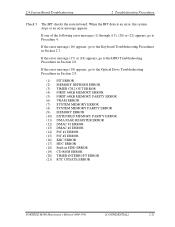
... the Optical Drive Troubleshooting Procedures in Section 2.9. (1) PIT ERROR (2) MEMORY REFRESH ERROR (3) TIMER CH.2 OUT ERROR (4) FIRST 64KB MEMORY ERROR (5) FIRST 64KB MEMORY PARITY ERROR (6) VRAM ERROR (7) SYSTEM MEMORY ERROR (8) SYSTEM MEMORY PARITY ERROR (9) MEMORY ERROR (10) EXTENDED MEMORY PARITY ERROR (11) DMA PAGE REGISTER ERROR (12) DMAC #1 ERROR (13) DMAC #2 ERROR (14) PIC #1 ERROR (15) PIC #2 ERROR (16) KBC ERROR (17) HDC ERROR (18) Built-in HDD ERROR (19) CD-ROM ERROR (20) TIMER INTERRUPT ERROR (21) RTC UPDATE ERROR PORTÉGÉ M500 Maintenance Manual (960...
... the Optical Drive Troubleshooting Procedures in Section 2.9. (1) PIT ERROR (2) MEMORY REFRESH ERROR (3) TIMER CH.2 OUT ERROR (4) FIRST 64KB MEMORY ERROR (5) FIRST 64KB MEMORY PARITY ERROR (6) VRAM ERROR (7) SYSTEM MEMORY ERROR (8) SYSTEM MEMORY PARITY ERROR (9) MEMORY ERROR (10) EXTENDED MEMORY PARITY ERROR (11) DMA PAGE REGISTER ERROR (12) DMAC #1 ERROR (13) DMAC #2 ERROR (14) PIC #1 ERROR (15) PIC #2 ERROR (16) KBC ERROR (17) HDC ERROR (18) Built-in HDD ERROR (19) CD-ROM ERROR (20) TIMER INTERRUPT ERROR (21) RTC UPDATE ERROR PORTÉGÉ M500 Maintenance Manual (960...

Maintenance Manual
Page 155
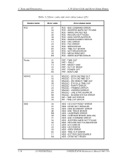
... ERROR HUB - SET ADDRESS ERROR HUB - GET STATUS ERROR HUB - OVER CURRENT ERROR USB - THORMISTOR ERROR(2) ROM - GET DESCR.ERROR (FIRST) USB - GET DESCR.ERROR (Whole) HUB - SET CONFIGURATION ERROR HUB - SET FEATURE ERROR(RESET) HUB - CLEAR FEATURE2 ERROR USB - SENSING ERROR(AC-ADAPT) ROM - THORMISTOR ERROR(3) RAM - CACHE MEMORY ERROR USB - GET DESCR.ERROR(SECOND) VRAM SIZE NOT SUPPORT PORTÉGÉ M500 Maintenance Manual (960-559) [CONFIDENTIAL] 3-35 Table 3-2 Error codes and error status names (1/3) Device name (Common) System Memory Keyboard Display Error code...
... ERROR HUB - SET ADDRESS ERROR HUB - GET STATUS ERROR HUB - OVER CURRENT ERROR USB - THORMISTOR ERROR(2) ROM - GET DESCR.ERROR (FIRST) USB - GET DESCR.ERROR (Whole) HUB - SET CONFIGURATION ERROR HUB - SET FEATURE ERROR(RESET) HUB - CLEAR FEATURE2 ERROR USB - SENSING ERROR(AC-ADAPT) ROM - THORMISTOR ERROR(3) RAM - CACHE MEMORY ERROR USB - GET DESCR.ERROR(SECOND) VRAM SIZE NOT SUPPORT PORTÉGÉ M500 Maintenance Manual (960-559) [CONFIDENTIAL] 3-35 Table 3-2 Error codes and error status names (1/3) Device name (Common) System Memory Keyboard Display Error code...
Maintenance Manual
Page 156
... 02 04 08 10 20 40 80 88 05 06 05 07 09 0B BB 08 01 02 04 10 20 40 80 11 AA Error status name FDD - DMA BOUNDARY ERROR FDD - DRIVE NOT READY 3-36 [CONFIDENTIAL] PORTÉGÉ M500 Maintenance Manual (960-559) POWER OFF PRT - ADDRESS MARK NOT FOUND HDD - WRITE BUFFER ERROR PRT - TIME OUT ERROR HDD -
... 02 04 08 10 20 40 80 88 05 06 05 07 09 0B BB 08 01 02 04 10 20 40 80 11 AA Error status name FDD - DMA BOUNDARY ERROR FDD - DRIVE NOT READY 3-36 [CONFIDENTIAL] PORTÉGÉ M500 Maintenance Manual (960-559) POWER OFF PRT - ADDRESS MARK NOT FOUND HDD - WRITE BUFFER ERROR PRT - TIME OUT ERROR HDD -

Maintenance Manual
Page 251
... release them. 3. To remove the memory module, make sure the computer is in boot mode and powered off when you remove or insert a memory module. Never press hard or bend the memory module. Press two latches outward to remove. M2.5×3S S-THIN HEAD Memory cover Latch Memory module A Latch Memory module B Figure 4-10 Removing the memory module PORTÉGÉ M500 Maintenance Manual (960-559) [CONFIDENTIAL] 4-21 4.8 Memory module 4 Replacement Procedures 4.8 Memory module Removing the Memory module CAUTION: The power must be turned off , follow the...
... release them. 3. To remove the memory module, make sure the computer is in boot mode and powered off when you remove or insert a memory module. Never press hard or bend the memory module. Press two latches outward to remove. M2.5×3S S-THIN HEAD Memory cover Latch Memory module A Latch Memory module B Figure 4-10 Removing the memory module PORTÉGÉ M500 Maintenance Manual (960-559) [CONFIDENTIAL] 4-21 4.8 Memory module 4 Replacement Procedures 4.8 Memory module Removing the Memory module CAUTION: The power must be turned off , follow the...
Maintenance Manual
Page 276
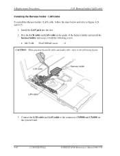
... ×1 CAUTION: When passing the LCD cable and LAN cable, refer to the connectors CN5000 and CN4100 on the system board. 4-46 [CONFIDENTIAL] PORTÉGÉ M500 Maintenance Manual (960-559) LCD cable Harness holder LAN cable 3. Connect the LCD cable and LAN cable to the following figure. Install the LAN jack into the slot. 2. 4 Replacement Procedures 4.18 Harness holder / LAN cable Installing the Harness holder / LAN cable To install the Harness holder / LAN cable, follow the steps below and refer...
... ×1 CAUTION: When passing the LCD cable and LAN cable, refer to the connectors CN5000 and CN4100 on the system board. 4-46 [CONFIDENTIAL] PORTÉGÉ M500 Maintenance Manual (960-559) LCD cable Harness holder LAN cable 3. Connect the LCD cable and LAN cable to the following figure. Install the LAN jack into the slot. 2. 4 Replacement Procedures 4.18 Harness holder / LAN cable Installing the Harness holder / LAN cable To install the Harness holder / LAN cable, follow the steps below and refer...


