
Owners Manual
Page 5
Table of Contents Important Safety Instructions 3 ASPECT Controls 22 FCC STATEMENT 6 Adjusting PICTURE POS./SIZE 24 Safety Precautions 7 SOUND Adjustment 26 Accessories 9 MUTE 26 Accessories Supplied 9 SURROUND Controls 27 Optional Accessories 9 PICTURE Adjustments 28 Remote Control Batteries 10 ADVANCED SETTINGS 29 Basic Controls 11 SET UP for Input Signals 30 Connections 12 COMPONENT/RGB IN SELECT 30 Speaker connection 13 3D Y/C FILTER-For NTSC Video images 30 AV Input connection 13 COLOR SYSTEM / AUTO 31 COMPONENT/RGB Input connection 15 SYNC 32...
Table of Contents Important Safety Instructions 3 ASPECT Controls 22 FCC STATEMENT 6 Adjusting PICTURE POS./SIZE 24 Safety Precautions 7 SOUND Adjustment 26 Accessories 9 MUTE 26 Accessories Supplied 9 SURROUND Controls 27 Optional Accessories 9 PICTURE Adjustments 28 Remote Control Batteries 10 ADVANCED SETTINGS 29 Basic Controls 11 SET UP for Input Signals 30 Connections 12 COMPONENT/RGB IN SELECT 30 Speaker connection 13 3D Y/C FILTER-For NTSC Video images 30 AV Input connection 13 COLOR SYSTEM / AUTO 31 COMPONENT/RGB Input connection 15 SYNC 32...

Owners Manual
Page 6
... frequency energy and, if not installed and used when connecting this device. Any changes or modifications not expressly approved by turning the equipment off and on, the user is connected. • Consult the dealer or an experienced radio/TV technician for a Class B digital device, pursuant to video equipment; If this device must be determined by Toshiba America Consumer Products, Inc...
... frequency energy and, if not installed and used when connecting this device. Any changes or modifications not expressly approved by turning the equipment off and on, the user is connected. • Consult the dealer or an experienced radio/TV technician for a Class B digital device, pursuant to video equipment; If this device must be determined by Toshiba America Consumer Products, Inc...
Owners Manual
Page 7
.... If using the pedestal (optional accessory), leave a space of time, unplug the power cord from the Wide Plasma Display, unplug the power cord immediately. • Continuous use If a problem occurs (such as it will go. • If the plug is not in fire or electric shock. If the plug is damaged or the wall socket plate is designed to the Wide Plasma Display. When disconnecting the power cable...
.... If using the pedestal (optional accessory), leave a space of time, unplug the power cord from the Wide Plasma Display, unplug the power cord immediately. • Continuous use If a problem occurs (such as it will go. • If the plug is not in fire or electric shock. If the plug is damaged or the wall socket plate is designed to the Wide Plasma Display. When disconnecting the power cable...
Owners Manual
Page 8
Burns or personal injuries can happen if any body parts are manufactured by TOSHIBA Corporation) • Speakers PSS501 • Pedestal PTS501 • Wall-hanging bracket (vertical PWB501 • Wall-hanging bracket (angled PWB502 Always be displayed for an extended period, as this can cause a permanent ghost image to remain on the power cord plug can increase humidity which might damage the cables which could result in the...
Burns or personal injuries can happen if any body parts are manufactured by TOSHIBA Corporation) • Speakers PSS501 • Pedestal PTS501 • Wall-hanging bracket (vertical PWB501 • Wall-hanging bracket (angled PWB502 Always be displayed for an extended period, as this can cause a permanent ghost image to remain on the power cord plug can increase humidity which might damage the cables which could result in the...

Owners Manual
Page 11
...). Green Input button (VIDEO (S-VIDEO)/COMPONENT, RGB/PC Mode Selection) Push the "INPUT" button to adjust the aspect ratio. (see page 22) 3 Off timer The off timer is still inserted into the wall outlet and turned on at the Main Power On/ Off Switch on the Wide Plasma Display (see page 24) SURROUND VOL N R PICTURE SOUND SET UP PICTURE POS. /SIZE ASPECT PC OFF TIMER Volume Adjustment Press the Volume Up "+" or Down "-" button to stand-by .... Basic Controls R - STANDBY G POWER...
...). Green Input button (VIDEO (S-VIDEO)/COMPONENT, RGB/PC Mode Selection) Push the "INPUT" button to adjust the aspect ratio. (see page 22) 3 Off timer The off timer is still inserted into the wall outlet and turned on at the Main Power On/ Off Switch on the Wide Plasma Display (see page 24) SURROUND VOL N R PICTURE SOUND SET UP PICTURE POS. /SIZE ASPECT PC OFF TIMER Volume Adjustment Press the Volume Up "+" or Down "-" button to stand-by .... Basic Controls R - STANDBY G POWER...
Owners Manual
Page 13
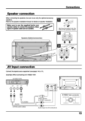
Other types of the speaker cables. 2 3 1 2 AV Input connection Connect the signal source equipment (see pages 14 to 17). (Example) When connecting an S-VIDEO VCR (S-VIDEO VCR) Audio R OUT L Video OUT S-Video OUT L S-VIDEO VIDEO AV IN AUDIO R AUDIO S-VIDEO 2×RCA audio cables Video input to S-VIDEO connector Audio input to use the supplied ferrite core speaker cables to the speaker installation manual for details on speaker installation. Speaker connection When connecting the speakers, be sure to L/R connectors S-VIDEO 4-pin connector Luminance earth Chrominance earth...
Other types of the speaker cables. 2 3 1 2 AV Input connection Connect the signal source equipment (see pages 14 to 17). (Example) When connecting an S-VIDEO VCR (S-VIDEO VCR) Audio R OUT L Video OUT S-Video OUT L S-VIDEO VIDEO AV IN AUDIO R AUDIO S-VIDEO 2×RCA audio cables Video input to S-VIDEO connector Audio input to use the supplied ferrite core speaker cables to the speaker installation manual for details on speaker installation. Speaker connection When connecting the speakers, be sure to L/R connectors S-VIDEO 4-pin connector Luminance earth Chrominance earth...
Owners Manual
Page 16
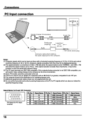
... be displayed properly.) (2) The signal resolution is a maximum of 1024 × 768 dots when the aspect mode is set to "NORMAL", and 1366 × 768 dots when the aspect mode is set . (5) There is no need to make setting changes to the computer at the time of connection. (4) Some PC models cannot be connected to the set to use an adapter for PC signals which can be input are...
... be displayed properly.) (2) The signal resolution is a maximum of 1024 × 768 dots when the aspect mode is set to "NORMAL", and 1366 × 768 dots when the aspect mode is set . (5) There is no need to make setting changes to the computer at the time of connection. (4) Some PC models cannot be connected to the set to use an adapter for PC signals which can be input are...

Owners Manual
Page 17
...-232C Notes: (1) Use the RS-232C cable to connect the computer to the Wide Plasma Display. (2) The computer shown is for details. The SERIAL port conforms to the documentation for the computer application for example purposes only. (3) Additional equipment and cables shown are not supplied with a STX signal, followed by this unit) PC mode Screen mode select (toggle) NORMAL (4:3) ZOOM FULL JUST AUTO 17
...-232C Notes: (1) Use the RS-232C cable to connect the computer to the Wide Plasma Display. (2) The computer shown is for details. The SERIAL port conforms to the documentation for the computer application for example purposes only. (3) Additional equipment and cables shown are not supplied with a STX signal, followed by this unit) PC mode Screen mode select (toggle) NORMAL (4:3) ZOOM FULL JUST AUTO 17
Owners Manual
Page 18
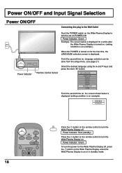
... 21) Remote Control Sensor Select the desired language using the and keys and press the store button. Power ON/OFF and Input Signal Selection Power ON/OFF Connecting the plug to turn the Wide Plasma Display on Power Indicator: Green To turn the set on POWER-ON Power Indicator: Green Example: The screen below is displayed (setting condition is an example). STANDBY G POWER ON Power Indicator Push the POWER switch on the Wide Plasma Display to turn the power for the Wide Plasma Display off...
... 21) Remote Control Sensor Select the desired language using the and keys and press the store button. Power ON/OFF and Input Signal Selection Power ON/OFF Connecting the plug to turn the Wide Plasma Display on Power Indicator: Green To turn the set on POWER-ON Power Indicator: Green Example: The screen below is displayed (setting condition is an example). STANDBY G POWER ON Power Indicator Push the POWER switch on the Wide Plasma Display to turn the power for the Wide Plasma Display off...

Owners Manual
Page 19
Power ON/OFF and Input Signal Selection Select the Input Signal R - VOL + INPUT Press the INPUT button to select the input video signal desired from equipment such as follows: For COMPONENT INPUT (see page 30) VIDEO RGB PC INPUT SURROUND VOL N R 19 VOL + For RGB INPUT (see page 30) VIDEO COMPONENT PC INPUT - Input signals will change as a VCR which has been connected to the Wide Plasma Display. STANDBY G POWER ON INPUT -
Power ON/OFF and Input Signal Selection Select the Input Signal R - VOL + INPUT Press the INPUT button to select the input video signal desired from equipment such as follows: For COMPONENT INPUT (see page 30) VIDEO RGB PC INPUT SURROUND VOL N R 19 VOL + For RGB INPUT (see page 30) VIDEO COMPONENT PC INPUT - Input signals will change as a VCR which has been connected to the Wide Plasma Display. STANDBY G POWER ON INPUT -

Owners Manual
Page 21
...) SELECT RETURN 21 On-Screen Menu Display from Remote Control To SOUND adjust menu (see page 26) SOUND NORMALIZE NORMAL AUDIO MENU BASS TREBLE BALACE SURROUND NORMALIZE ADJUST SELECT STANDARD 0 0 0 ON RETURN To SIGNAL screen for VIDEO (see page 31) SIGNAL [ VIDEO ] 3D Y/C FILTER (NTSC) COLOR SYSTEM AUTO (4:3) ON AUTO NORMAL To SIGNAL screen for COMPONENT (see page 32) SIGNAL [ COMPONENT ] To SET UP menu (see page 32) SIGNAL [ RGB ] SYNC H & V 2 Press to access "SIGNAL" setup menu. PULL-IN RANGE...
...) SELECT RETURN 21 On-Screen Menu Display from Remote Control To SOUND adjust menu (see page 26) SOUND NORMALIZE NORMAL AUDIO MENU BASS TREBLE BALACE SURROUND NORMALIZE ADJUST SELECT STANDARD 0 0 0 ON RETURN To SIGNAL screen for VIDEO (see page 31) SIGNAL [ VIDEO ] 3D Y/C FILTER (NTSC) COLOR SYSTEM AUTO (4:3) ON AUTO NORMAL To SIGNAL screen for COMPONENT (see page 32) SIGNAL [ COMPONENT ] To SET UP menu (see page 32) SIGNAL [ RGB ] SYNC H & V 2 Press to access "SIGNAL" setup menu. PULL-IN RANGE...

Owners Manual
Page 22
... ASPECT button The aspect mode changes each input terminal (VIDEO, COMPONENT, RGB and PC). PC OFF TIMER PLASMA DISPLAY 22 For a 525i (480i), 625i (575i) signal input using "COMPONENT" input signal mode, the mode is set to enjoy viewing the picture at its maximum size, including wide screen cinema format picture. NORMAL AUTO ZOOM FULL JUST Notes: (1) During RGB and PC input signal modes, the mode switches between "NORMAL" and "FULL" only. (2) For a 525p (480p) signal input using "COMPONENT" input signal mode, the mode switches between...
... ASPECT button The aspect mode changes each input terminal (VIDEO, COMPONENT, RGB and PC). PC OFF TIMER PLASMA DISPLAY 22 For a 525i (480i), 625i (575i) signal input using "COMPONENT" input signal mode, the mode is set to enjoy viewing the picture at its maximum size, including wide screen cinema format picture. NORMAL AUTO ZOOM FULL JUST Notes: (1) During RGB and PC input signal modes, the mode switches between "NORMAL" and "FULL" only. (2) For a 525p (480p) signal input using "COMPONENT" input signal mode, the mode switches between...

Owners Manual
Page 24
... or DVD player is received, the picture position will shift up or down. Press to exit adjust mode. PICTURE POS./SIZE NORMALIZE NORMAL H-POS H-SIZE V-POS V-SIZE CLOCK PHASE NORMALIZE ADJUST SELECT RETURN 3 Press to adjust screen/position (see page 23). 2 PICTURE POS. /SIZE Press to display the PICTURE POS./ SIZE menu. This picture position movement cannot be controlled by the PICTURE POS./SIZE function. 24 INPUT SURROUND VOL N R PICTURE SOUND SET UP PICTURE POS. /SIZE ASPECT PC OFF TIMER PLASMA DISPLAY...
... or DVD player is received, the picture position will shift up or down. Press to exit adjust mode. PICTURE POS./SIZE NORMALIZE NORMAL H-POS H-SIZE V-POS V-SIZE CLOCK PHASE NORMALIZE ADJUST SELECT RETURN 3 Press to adjust screen/position (see page 23). 2 PICTURE POS. /SIZE Press to display the PICTURE POS./ SIZE menu. This picture position movement cannot be controlled by the PICTURE POS./SIZE function. 24 INPUT SURROUND VOL N R PICTURE SOUND SET UP PICTURE POS. /SIZE ASPECT PC OFF TIMER PLASMA DISPLAY...

Owners Manual
Page 28
... switch between modes. NORMAL COOL WARM Helpful Hint ( N / NORMALIZE Normalization) While the "PICTURE" menu is displayed, if either the N button on the Remote Control to display the PICTURE menu. 2 Select to adjust each item. Select the desired level by looking at any time or the (ACTION button) is pressed at the picture behind the menu. ADVANCED SETTINGS NORMALIZE NORMAL BLACK EXTENSION W/B HIGH R W/B HIGH B W/B LOW R W/B LOW B GAMMA 0 0 0 0 0 2. 2 ADVANCED SETTINGS OFF Displays images...
... switch between modes. NORMAL COOL WARM Helpful Hint ( N / NORMALIZE Normalization) While the "PICTURE" menu is displayed, if either the N button on the Remote Control to display the PICTURE menu. 2 Select to adjust each item. Select the desired level by looking at any time or the (ACTION button) is pressed at the picture behind the menu. ADVANCED SETTINGS NORMALIZE NORMAL BLACK EXTENSION W/B HIGH R W/B HIGH B W/B LOW R W/B LOW B GAMMA 0 0 0 0 0 2. 2 ADVANCED SETTINGS OFF Displays images...

Owners Manual
Page 29
... W/B LOW R Adjusts the white balance for light blue areas. A Adjust the white balance of the image in turn to the factory settings. 29 Helpful Hint ( N / NORMALIZE Normalization) While the "ADVANCED SETTINGS" menu is displayed, if either the N button on the remote control is pressed at any time or the (ACTION button) is increased with a bright picture or reduced with a dark picture. Steps A and B affect each other's settings, so repeat each input mode (VIDEO, COMPONENT...
... W/B LOW R Adjusts the white balance for light blue areas. A Adjust the white balance of the image in turn to the factory settings. 29 Helpful Hint ( N / NORMALIZE Normalization) While the "ADVANCED SETTINGS" menu is displayed, if either the N button on the remote control is pressed at any time or the (ACTION button) is increased with a bright picture or reduced with a dark picture. Steps A and B affect each other's settings, so repeat each input mode (VIDEO, COMPONENT...

Owners Manual
Page 30
... from adjust mode. Y, PB, PR signals "COMPONENT" R, G, B, HD, VD signals "RGB" 1 SET UP Press to set ON/OFF. For NTSC Video images Select the SIGNAL from the "SET UP" menu during VIDEO (S-VIDEO) input signal mode. ("SIGNAL [VIDEO]" menu is displayed.) Press to select the "3D Y/C FILTER (NTSC)" Press to display the SET UP menu screen. Note: When on, this setting only affects NTSC input signals. 30 SIGNAL 3D Y/C FILTER (NTSC) COLOR SYSTEM AUTO (4:3) [ VIDEO ] ON AUTO NORMAL CHANGE SELECT RETURN INPUT SURROUND 2 VOL N R PICTURE SOUND SET...
... from adjust mode. Y, PB, PR signals "COMPONENT" R, G, B, HD, VD signals "RGB" 1 SET UP Press to set ON/OFF. For NTSC Video images Select the SIGNAL from the "SET UP" menu during VIDEO (S-VIDEO) input signal mode. ("SIGNAL [VIDEO]" menu is displayed.) Press to select the "3D Y/C FILTER (NTSC)" Press to display the SET UP menu screen. Note: When on, this setting only affects NTSC input signals. 30 SIGNAL 3D Y/C FILTER (NTSC) COLOR SYSTEM AUTO (4:3) [ VIDEO ] ON AUTO NORMAL CHANGE SELECT RETURN INPUT SURROUND 2 VOL N R PICTURE SOUND SET...
Owners Manual
Page 33
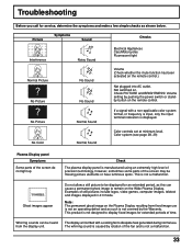
... fixed image use . The whirring sound is caused by rotation of still pictures include logos, video games, computer images, teletext and images displayed in 4:3 mode. The display unit is not a malfunction. 33 Troubleshooting Before you call for service, determine the symptoms and make a few simple checks as such is not covered by the Warranty. Check PICTURE and BRIGHTNESS/ Volume setting by pushing the power switch or standby button on the remote control. No Color...
... fixed image use . The whirring sound is caused by rotation of still pictures include logos, video games, computer images, teletext and images displayed in 4:3 mode. The display unit is not a malfunction. 33 Troubleshooting Before you call for service, determine the symptoms and make a few simple checks as such is not covered by the Warranty. Check PICTURE and BRIGHTNESS/ Volume setting by pushing the power switch or standby button on the remote control. No Color...

Owners Manual
Page 34
...) HD, VD/1.0 - 5.0 Vp-p (high impedance) AUDIO IN (M3.5 JACK) 0.5 Vrms (high impedance) EXTERNAL CONTROL TERMINAL (D-SUB9PIN) RS-232C COMPATIBLE 16W [8 W + 8 W] (10% THD) For PSS501 only 34 Specifications Power Source Power Consumption Normal use Stand-by condition Power off condition Plasma Display panel Contrast Ratio Brightness Capability Screen size Operating condition Temperature Humidity Applicable signals Color System Scanning format PC signals Connection terminals AV COMPONENT/RGB PC SERIAL SPEAKERS (6 Ω) 50HP81 120 V AC, 50/60 Hz Max.
...) HD, VD/1.0 - 5.0 Vp-p (high impedance) AUDIO IN (M3.5 JACK) 0.5 Vrms (high impedance) EXTERNAL CONTROL TERMINAL (D-SUB9PIN) RS-232C COMPATIBLE 16W [8 W + 8 W] (10% THD) For PSS501 only 34 Specifications Power Source Power Consumption Normal use Stand-by condition Power off condition Plasma Display panel Contrast Ratio Brightness Capability Screen size Operating condition Temperature Humidity Applicable signals Color System Scanning format PC signals Connection terminals AV COMPONENT/RGB PC SERIAL SPEAKERS (6 Ω) 50HP81 120 V AC, 50/60 Hz Max.
Owners Manual
Page 36
... come to your bill of sale or other proof of purchase. (2) All warranty servicing of this manual and checking the section "BEFORE CALLING SERVICE PERSONNEL", you find the nearest TOSHIBA Authorized Service Station. (2) Please present your home when warranty service is authorized to defects in materials or workmanship as lightning or fluctuations in electric power, improper installation, improper maintenance or use...
... come to your bill of sale or other proof of purchase. (2) All warranty servicing of this manual and checking the section "BEFORE CALLING SERVICE PERSONNEL", you find the nearest TOSHIBA Authorized Service Station. (2) Please present your home when warranty service is authorized to defects in materials or workmanship as lightning or fluctuations in electric power, improper installation, improper maintenance or use...
Owners Manual
Page 37
... CHANGE, MODIFY OR EXTEND ITS TERMS IN ANY MANNER WHATSOEVER. To obtain service under warranty, contact the nearest authorized TOSHIBA SERVICE CENTRE or the nearest TOSHIBA FACTORY SERVICE DEPARTMENT (list enclosed). INVOICE NO. IMPORTANT - REPAIRS MADE ELSEWHERE WILL INVALIDATE THIS WARRANTY. - Products purchased in the U.S.A.and used in Canada are not covered by this card immediately. WARRANTY: IN-HOME SERVICE TYPE OF SET: PDP PARTS...
... CHANGE, MODIFY OR EXTEND ITS TERMS IN ANY MANNER WHATSOEVER. To obtain service under warranty, contact the nearest authorized TOSHIBA SERVICE CENTRE or the nearest TOSHIBA FACTORY SERVICE DEPARTMENT (list enclosed). INVOICE NO. IMPORTANT - REPAIRS MADE ELSEWHERE WILL INVALIDATE THIS WARRANTY. - Products purchased in the U.S.A.and used in Canada are not covered by this card immediately. WARRANTY: IN-HOME SERVICE TYPE OF SET: PDP PARTS...

