Owner's Manual - English
Page 2
Television Stand Model 50HM66 ST5066 56HM66 ST5666 Welcome to Toshiba Thank you turn the TV off . This is a function of the Quick Restart™ feature and is not a sign of malfunction. page 20). 8) The yellow and blue LED lights at right). 4) The TV's display is a trademark of Cable ...the LEDs are viewing, it is possible, although unlikely, that the TV loses and regains power within a few minutes. This is normal and is for several cooling fans to get the most innovative DLP™ projection TVs on again within a few minutes; however, an occasional pixel (dot...
Television Stand Model 50HM66 ST5066 56HM66 ST5666 Welcome to Toshiba Thank you turn the TV off . This is a function of the Quick Restart™ feature and is not a sign of malfunction. page 20). 8) The yellow and blue LED lights at right). 4) The TV's display is a trademark of Cable ...the LEDs are viewing, it is possible, although unlikely, that the TV loses and regains power within a few minutes. This is normal and is for several cooling fans to get the most innovative DLP™ projection TVs on again within a few minutes; however, an occasional pixel (dot...
Owner's Manual - English
Page 21
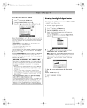
...The fans continue to the Terrestrial menu: Highlight Done and press T. page 47). This is a property of DLP™ TV lamp technology and is NOT a sign of the Quick Restart Shutdown mode and is a function of malfunction. Open the Terrestrial menu, highlight Signal Meter, and press T. This is not a TV ... ENTER Select CH RTN Back EXIT Exit 4 Press BbC c to appear on-screen in the Signal Meter screen may be lit solid) until the TV is on again within a few minutes; Signal Meter Signal Locked 0 Antenna Physical Digital Channel Virtual Digital Channel Done Peak 0 1 4 4/1 To ...
...The fans continue to the Terrestrial menu: Highlight Done and press T. page 47). This is a property of DLP™ TV lamp technology and is NOT a sign of the Quick Restart Shutdown mode and is a function of malfunction. Open the Terrestrial menu, highlight Signal Meter, and press T. This is not a TV ... ENTER Select CH RTN Back EXIT Exit 4 Press BbC c to appear on-screen in the Signal Meter screen may be lit solid) until the TV is on again within a few minutes; Signal Meter Signal Locked 0 Antenna Physical Digital Channel Virtual Digital Channel Done Peak 0 1 4 4/1 To ...
Owner's Manual - English
Page 46
... unit replacement and care" in Chapter 8 to appear on-screen. Check to make sure all slots and openings in again and turn ON the TV. Voice announce - - - "Fan stopped." - - click "Home Entertainment," and then click "Support." 46 HM66 (E/F) Web 213:276 LED Indication 1) Blue is ON (solid).... Solutions at 1-800-631-3811. • In Canada, locate the nearest Toshiba authorized service depot by directing your web browser to restart itself eight times (see item #4). Fan stopped (POD). This is a property of DLP TV lamp technology and is NOT a sign of malfunction. "Lamp not working properly...
... unit replacement and care" in Chapter 8 to appear on-screen. Check to make sure all slots and openings in again and turn ON the TV. Voice announce - - - "Fan stopped." - - click "Home Entertainment," and then click "Support." 46 HM66 (E/F) Web 213:276 LED Indication 1) Blue is ON (solid).... Solutions at 1-800-631-3811. • In Canada, locate the nearest Toshiba authorized service depot by directing your web browser to restart itself eight times (see item #4). Fan stopped (POD). This is a property of DLP TV lamp technology and is NOT a sign of malfunction. "Lamp not working properly...
Service Manual
Page 5
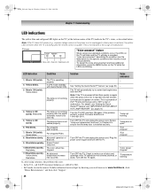
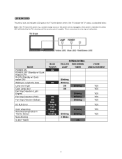
... Detection (Light Engine) Fan Stop Detection (POD) Fan Stop Detection (Ballast) IIC BUS Error Color wheel stop Abnormal temperature in Thermo Sensor Seine Booting SLEEP TIMER BLUE POWER ON ON ON ON Slow blinking Fast blinking Fast blinking 50HM66/56HM66 YELLOW RED/GREEN LAMP TIMER VOICE ANNOUNCEMENT Blinking... 3 Blinks ON 4 LED BLINK CODES The yellow, blue, and red/green LED lights on the TV (at the bottom center of the TV) indicate the TV's status, as described below: Note: If the TV loses A/C power (e.g., a power outage occurs or the power cord is unplugged), when power is restored...
... Detection (Light Engine) Fan Stop Detection (POD) Fan Stop Detection (Ballast) IIC BUS Error Color wheel stop Abnormal temperature in Thermo Sensor Seine Booting SLEEP TIMER BLUE POWER ON ON ON ON Slow blinking Fast blinking Fast blinking 50HM66/56HM66 YELLOW RED/GREEN LAMP TIMER VOICE ANNOUNCEMENT Blinking... 3 Blinks ON 4 LED BLINK CODES The yellow, blue, and red/green LED lights on the TV (at the bottom center of the TV) indicate the TV's status, as described below: Note: If the TV loses A/C power (e.g., a power outage occurs or the power cord is unplugged), when power is restored...

Service Manual
Page 11
Remove the door SW unit by following steps 1 - 7 in reverse. Remove the light engine. Reassemble the light engine by unscrewing as shown below. 6. Remove screws 1, 2, and 3 securing the lamp fan cover and remove the lamp fan cover. 10 Lamp Fan Replacement 1. 5. Disconnect the ballast cable and remove the ballast unit from the retaining clips 1 - 4. 7.
Remove the door SW unit by following steps 1 - 7 in reverse. Remove the light engine. Reassemble the light engine by unscrewing as shown below. 6. Remove screws 1, 2, and 3 securing the lamp fan cover and remove the lamp fan cover. 10 Lamp Fan Replacement 1. 5. Disconnect the ballast cable and remove the ballast unit from the retaining clips 1 - 4. 7.

Service Manual
Page 12
Remove the Ballast Fan cable (1) and Lamp Fan cable (2). 3. Remove the 4 rubber corners from the old lamp fan and place them on the new lamp fan. 5. Remove the 2 screws securing the Lamp fan and remove the lamp fan. 4. Assemble the new fan to the light engine by following steps 1 - 4 in reverse. 11 2.
Remove the Ballast Fan cable (1) and Lamp Fan cable (2). 3. Remove the 4 rubber corners from the old lamp fan and place them on the new lamp fan. 5. Remove the 2 screws securing the Lamp fan and remove the lamp fan. 4. Assemble the new fan to the light engine by following steps 1 - 4 in reverse. 11 2.

Service Manual
Page 13
Remove the DMD Fan cable. 2. Remove the DMD Fan casing by removing screws 1, 2, and 3. 3. DMD Fan Replacement 1. Remove the 2 screws securing the LVDS connector. 12
Remove the DMD Fan cable. 2. Remove the DMD Fan casing by removing screws 1, 2, and 3. 3. DMD Fan Replacement 1. Remove the 2 screws securing the LVDS connector. 12

Service Manual
Page 14
4. Remove the DMD shield case by following steps 1 - 5 in reverse. Remove the retaining pins from the fan. 13 Assemble the new DMD fan by removing screws 1 and 2. 5. Ballast Fan Replacement 1. Remove the DMD Fan by removing screws 1 and 2. 6.
4. Remove the DMD shield case by following steps 1 - 5 in reverse. Remove the retaining pins from the fan. 13 Assemble the new DMD fan by removing screws 1 and 2. 5. Ballast Fan Replacement 1. Remove the DMD Fan by removing screws 1 and 2. 6.

Service Manual
Page 15
2. Disconnect the thermostat lead wires. 14 Thermostat Breaker Replacement 1. Fix the Ballast Fan with two pins. Replace the Ballast Fan. 3.
2. Disconnect the thermostat lead wires. 14 Thermostat Breaker Replacement 1. Fix the Ballast Fan with two pins. Replace the Ballast Fan. 3.
Service Manual
Page 17
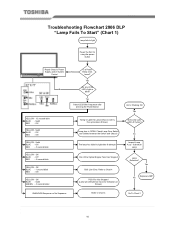
... Switch and Cables between the Switch and Chassis The lamp has failed to Chart 4 Unit is OPEN. Yes Replace LAMP No Go To Chart 2 2007 Toshiba America Consumer Products, LLC. Off YELLOW - Off BLUE - Solid RED - Off YELLOW - Solid GREEN - .5 second blinks UNKNOWN Sequence or No Sequence Trying to light... light after pressing the Power Button YELLOW - 1/2 second blink BLUE - Off RED - .5 second blink YELLOW - Off YELLOW - Yes Do any of the Optical Engine Fans Has Stopped BUS Line Error. Off BLUE - No Inspect Lamp Assy / Substitute Lamp Lamp Defective? Off RED -
... Switch and Cables between the Switch and Chassis The lamp has failed to Chart 4 Unit is OPEN. Yes Replace LAMP No Go To Chart 2 2007 Toshiba America Consumer Products, LLC. Off YELLOW - Off BLUE - Solid RED - Off YELLOW - Solid GREEN - .5 second blinks UNKNOWN Sequence or No Sequence Trying to light... light after pressing the Power Button YELLOW - 1/2 second blink BLUE - Off RED - .5 second blink YELLOW - Off YELLOW - Yes Do any of the Optical Engine Fans Has Stopped BUS Line Error. Off BLUE - No Inspect Lamp Assy / Substitute Lamp Lamp Defective? Off RED -

Service Manual
Page 20
... PB90 Pin 4? Yes V1.0 Yes No 3.3vdc at PB80B Pin 19 and 20? No Change TV-Micro PCB Yes Change Regulator PCB P822B PB90 CS110 PB504 Back AV & Regulator PCB ” 2007 Toshiba America Consumer Products, LLC. Power Does Not Cycle Troubleshooting Flowchart 2006 DLP "Dead / Does not ...Power Supply Yes Yes Location PCB PB504 Back AV CS110 Back AV P823B Regulator P822B Regulator PB90 Regulator PB80B Regulator Yes Are the Optic Engine Fans Running? Page 5 of PB90? Yes 9 Volts at Capacitor CS110(+) No 6 Volts at P823B Pin 6? Yes Change Digital PCB Is ...
... PB90 Pin 4? Yes V1.0 Yes No 3.3vdc at PB80B Pin 19 and 20? No Change TV-Micro PCB Yes Change Regulator PCB P822B PB90 CS110 PB504 Back AV & Regulator PCB ” 2007 Toshiba America Consumer Products, LLC. Power Does Not Cycle Troubleshooting Flowchart 2006 DLP "Dead / Does not ...Power Supply Yes Yes Location PCB PB504 Back AV CS110 Back AV P823B Regulator P822B Regulator PB90 Regulator PB80B Regulator Yes Are the Optic Engine Fans Running? Page 5 of PB90? Yes 9 Volts at Capacitor CS110(+) No 6 Volts at P823B Pin 6? Yes Change Digital PCB Is ...


