

Instruction Manual
Page 2
... Spring on Handlebar 67 Stop Buffers 68 Buffers on Machines with Manual Fuel Pump 85 12.5 Carburetor 88 12.5.1 Leakage Test 89 RA_737_00_01_01 MS 231, MS 231 C, MS 251, MS 251 C q © ANDREAS STIHL AG & Co. QuickStop Super 73 10.3.1 Switch Lever QuickStop Super 74 10.3.2 Lockout Lever - Clutch 19 4.1 Clutch Drum 19 4.2 Clutch 19 5. Ignition System...
... Spring on Handlebar 67 Stop Buffers 68 Buffers on Machines with Manual Fuel Pump 85 12.5 Carburetor 88 12.5.1 Leakage Test 89 RA_737_00_01_01 MS 231, MS 231 C, MS 251, MS 251 C q © ANDREAS STIHL AG & Co. QuickStop Super 73 10.3.1 Switch Lever QuickStop Super 74 10.3.2 Lockout Lever - Clutch 19 4.1 Clutch Drum 19 4.2 Clutch 19 5. Ignition System...

Instruction Manual
Page 4
...bulletins for the use of movement @ 4.2 =Reference to another chapter, i.e. Service manuals and all special servicing tools currently available from STIHL. Engage the bar mounting stud in the outer bore in the mounting plate and secure the machine in position with two screws (1) and... since publication of the relevant parts list to this example. 1 3 2 Servicing and repairs are included in the "STIHL Special Tools" manual. MS 231, MS 231 C, MS 251, MS 251 C 3 Symbols are made considerably easier if the machine is issued. To do this service manual. Refer to the latest...
...bulletins for the use of movement @ 4.2 =Reference to another chapter, i.e. Service manuals and all special servicing tools currently available from STIHL. Engage the bar mounting stud in the outer bore in the mounting plate and secure the machine in position with two screws (1) and... since publication of the relevant parts list to this example. 1 3 2 Servicing and repairs are included in the "STIHL Special Tools" manual. MS 231, MS 231 C, MS 251, MS 251 C 3 Symbols are made considerably easier if the machine is issued. To do this service manual. Refer to the latest...
Instruction Manual
Page 5
... due to overheating. 4 MS 231, MS 231 C, MS 251, MS 251 C Improper handling may result in burns or other fasteners in all machine components that have to be tightened to a specific torque or coated with the connector, preferably by the STIHL part number, the { logo and the STIHL parts symbol K This symbol...carrying out repairs or mounting the machine to ensure the tightness of it properly in accordance with the shroud mounted in the course of STIHL press fluid, b 14. The specifications must be performed outdoors only. Avoid damaging the hose barb - Other press fluids are heated ...
... due to overheating. 4 MS 231, MS 231 C, MS 251, MS 251 C Improper handling may result in burns or other fasteners in all machine components that have to be tightened to a specific torque or coated with the connector, preferably by the STIHL part number, the { logo and the STIHL parts symbol K This symbol...carrying out repairs or mounting the machine to ensure the tightness of it properly in accordance with the shroud mounted in the course of STIHL press fluid, b 14. The specifications must be performed outdoors only. Avoid damaging the hose barb - Other press fluids are heated ...
Instruction Manual
Page 31
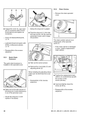
... STIHL multipurpose grease, b 14 - Remove the chain sprocket cover. 165RA007 TG 533RA058 TG 2310RA048 TG 1 3 : Inspect the cover (1), spur gear set (2), tensioner slide (3) and thrust pad (4) and replace as necessary. - Reassemble in the reverse sequence. - Reassemble in the reverse sequence. - Check the wing nut (1) and replace if necessary 30 MS 231, MS 231 C, MS 251, MS 251...
... STIHL multipurpose grease, b 14 - Remove the chain sprocket cover. 165RA007 TG 533RA058 TG 2310RA048 TG 1 3 : Inspect the cover (1), spur gear set (2), tensioner slide (3) and thrust pad (4) and replace as necessary. - Reassemble in the reverse sequence. - Reassemble in the reverse sequence. - Check the wing nut (1) and replace if necessary 30 MS 231, MS 231 C, MS 251, MS 251...

Instruction Manual
Page 49
... of the lead. : Pinch the hook of the leg spring into the spark plug boot. 48 MS 231, MS 231 C, MS 251, MS 251 C Remove the spark plug boot and pull the ignition lead out of the spark plug boot with STIHL press fluid, b 14 : Hold the ignition lead and leg spring together and push them into...
... of the lead. : Pinch the hook of the leg spring into the spark plug boot. 48 MS 231, MS 231 C, MS 251, MS 251 C Remove the spark plug boot and pull the ignition lead out of the spark plug boot with STIHL press fluid, b 14 : Hold the ignition lead and leg spring together and push them into...

Instruction Manual
Page 59
... entire starter mechanism, including the rewind spring, must be assumed that the starter mechanism is in the reverse sequence. 58 MS 231, MS 231 C, MS 251, MS 251 C At very low outside temperatures the lubricating oil on the function of the segment (1) to the holes on the other...TG 8.1 General 8.2 Fan housing Installing If the action of rewind spring, b 8.4 - Before installing, lubricate the rewind spring and starter post with STIHL special lubricant, b 14. : Take out the screw (1) with dirt. Relieve tension of the starter rope becomes very stiff and the rope rewinds very...
... entire starter mechanism, including the rewind spring, must be assumed that the starter mechanism is in the reverse sequence. 58 MS 231, MS 231 C, MS 251, MS 251 C At very low outside temperatures the lubricating oil on the function of the segment (1) to the holes on the other...TG 8.1 General 8.2 Fan housing Installing If the action of rewind spring, b 8.4 - Before installing, lubricate the rewind spring and starter post with STIHL special lubricant, b 14. : Take out the screw (1) with dirt. Relieve tension of the starter rope becomes very stiff and the rope rewinds very...

Instruction Manual
Page 62
... starter post so that the inner spring loop (arrow) engages the recess (1). Pull out the rope with grease, b 14 - MS 231, MS 231 C, MS 251, MS 251 C 61 Remove the fan housing and the segment, b 8.2 Models with STIHL special lubricant, b 14 Installing - The rewind spring may pop out and unwind. - Install the pawl(s) and spring clip, b 8.3 - Remove...
... starter post so that the inner spring loop (arrow) engages the recess (1). Pull out the rope with grease, b 14 - MS 231, MS 231 C, MS 251, MS 251 C 61 Remove the fan housing and the segment, b 8.2 Models with STIHL special lubricant, b 14 Installing - The rewind spring may pop out and unwind. - Install the pawl(s) and spring clip, b 8.3 - Remove...

Instruction Manual
Page 64
... this is not the case, tension the spring by one additional turn. - Relieve tension of the old rewind spring. MS 231, MS 231 C, MS 251, MS 251 C 63 Lubricate the replacement spring with frame with a few drops of STIHL special lubricant before installing, b 14 : Position the replacement spring with the starter grip and straighten it out. 2 1 2310RA220...
... this is not the case, tension the spring by one additional turn. - Relieve tension of the old rewind spring. MS 231, MS 231 C, MS 251, MS 251 C 63 Lubricate the replacement spring with frame with a few drops of STIHL special lubricant before installing, b 14 : Position the replacement spring with the starter grip and straighten it out. 2 1 2310RA220...

Instruction Manual
Page 65
Arrange the rewind spring (1) in its original position. : Fit the anchor loop in its seat in the reverse sequence. 64 MS 231, MS 231 C, MS 251, MS 251 C The rewind spring may pop out and unwind. - the frame is used as an assembly tool for installing a rewind spring ... engaged on models without ErgoStart. - Reassemble all other parts in the fan housing. - Lubricate the replacement spring with frame with a few drops of STIHL special lubricant before installing, b 14 : Position the replacement spring with ErgoStart If the rewind spring has popped out, refit it if necessary. 1 2...
Arrange the rewind spring (1) in its original position. : Fit the anchor loop in its seat in the reverse sequence. 64 MS 231, MS 231 C, MS 251, MS 251 C The rewind spring may pop out and unwind. - the frame is used as an assembly tool for installing a rewind spring ... engaged on models without ErgoStart. - Reassemble all other parts in the fan housing. - Lubricate the replacement spring with frame with a few drops of STIHL special lubricant before installing, b 14 : Position the replacement spring with ErgoStart If the rewind spring has popped out, refit it if necessary. 1 2...

Instruction Manual
Page 69
Use STIHL press fluid to simplify assembly, b 14 9.3.1 Stop Buffers The stop buffers are installed between the engine housing and tank housing at the ignition and clutch ... the reverse sequence. : Screw the bearing plug (1) into the bores while turning them back and forth to the bearing plug (1). : Push the stop buffers. 68 MS 231, MS 231 C, MS 251, MS 251 C
Use STIHL press fluid to simplify assembly, b 14 9.3.1 Stop Buffers The stop buffers are installed between the engine housing and tank housing at the ignition and clutch ... the reverse sequence. : Screw the bearing plug (1) into the bores while turning them back and forth to the bearing plug (1). : Push the stop buffers. 68 MS 231, MS 231 C, MS 251, MS 251 C

Instruction Manual
Page 70
...Insert and tighten down a little and hold it there. 1 1 : Position the buffers (1) with their tapered ends facing the bores (arrows). - MS 231, MS 231 C, MS 251, MS 251 C 69 Remove the filter base, b 12.3 1 2 1 1 1 2310RA249 TG 2310RA251 TG 2310RA253 TG 2 : Take out the screw (1). ...: Press the tank housing (2) down the screw (2) firmly. - 9.3.2 Buffers on the other parts in the reverse sequence. 9.4 Handlebar - Use STIHL press ...
...Insert and tighten down a little and hold it there. 1 1 : Position the buffers (1) with their tapered ends facing the bores (arrows). - MS 231, MS 231 C, MS 251, MS 251 C 69 Remove the filter base, b 12.3 1 2 1 1 1 2310RA249 TG 2310RA251 TG 2310RA253 TG 2 : Take out the screw (1). ...: Press the tank housing (2) down the screw (2) firmly. - 9.3.2 Buffers on the other parts in the reverse sequence. 9.4 Handlebar - Use STIHL press ...

Instruction Manual
Page 83
.... - Position filter base in the reverse sequence. 82 MS 231, MS 231 C, MS 251, MS 251 C Reassemble all other side of the buffer. 2310RA318 TG : Use punch-down tool 5910 890 4000 to simplify assembly, b 14 : Push peg (1) on the other parts in the carburetor box. 1 - Use STIHL press fluid to press the short circuit wire (1) into...
.... - Position filter base in the reverse sequence. 82 MS 231, MS 231 C, MS 251, MS 251 C Reassemble all other side of the buffer. 2310RA318 TG : Use punch-down tool 5910 890 4000 to simplify assembly, b 14 : Push peg (1) on the other parts in the carburetor box. 1 - Use STIHL press fluid to press the short circuit wire (1) into...

Instruction Manual
Page 84
Remove the carburetor, b 12.5 - Put the wiring harness with filter base to one side with STIHL press fluid to one side. 1 1 2 1 : Push the manifold flange (1) out of the air guide shroud (2) in the direction of the cylinder and pull... the stop (arrow) and lift it a 1 little. 2310RA325 TG 2310RA319 TG : Pull the rubber grommet (1) and wiring harness out of the air guide shroud. - MS 231, MS 231 C, MS 251, MS 251 C 83 Remove the carburetor carrier, b 12.8 - Remove the throttle rod, b 10.3.4 1 : Push the grommet (arrow) of manifold flange. - Installing 2310RA324 TG - ...
Remove the carburetor, b 12.5 - Put the wiring harness with filter base to one side with STIHL press fluid to one side. 1 1 2 1 : Push the manifold flange (1) out of the air guide shroud (2) in the direction of the cylinder and pull... the stop (arrow) and lift it a 1 little. 2310RA325 TG 2310RA319 TG : Pull the rubber grommet (1) and wiring harness out of the air guide shroud. - MS 231, MS 231 C, MS 251, MS 251 C 83 Remove the carburetor carrier, b 12.8 - Remove the throttle rod, b 10.3.4 1 : Push the grommet (arrow) of manifold flange. - Installing 2310RA324 TG - ...

Instruction Manual
Page 85
Install the carburetor carrier, b 12.8 2310RA328 TG 2 - Install filter base with STIHL press fluid to 1 pull the manifold flange (1) through the bore (arrow). : Ease the air guide shroud (1) over the stop (arrow) and push it is flush ... (arrow) until it is properly seated. 1 1 3 2310RA331 TG 2310RA326 TG 2 : Use the ends of the string (2) to simplify installation, b 14 - Install the carburetor, b 12.5 84 MS 231, MS 231 C, MS 251, MS 251 C
Install the carburetor carrier, b 12.8 2310RA328 TG 2 - Install filter base with STIHL press fluid to 1 pull the manifold flange (1) through the bore (arrow). : Ease the air guide shroud (1) over the stop (arrow) and push it is flush ... (arrow) until it is properly seated. 1 1 3 2310RA331 TG 2310RA326 TG 2 : Use the ends of the string (2) to simplify installation, b 14 - Install the carburetor, b 12.5 84 MS 231, MS 231 C, MS 251, MS 251 C

Instruction Manual
Page 87
- Use STIHL press fluid to simplify installation, b 14 - Remove the grommet, check and replace if necessary. 86 MS 231, MS 231 C, MS 251, MS 251 C Install fuel pump with fuel hoses and elbow connector, b 12.11.4 2310RA324 TG : Place the air guide shroud (1)... 2310RA325 TG - Remove the air guide shroud. 2 1 3 4 2310RA342 TG 2 1 1 - Coat outside of manifold flange. 1 2310RA341 TG - Coat manifold flange with STIHL press fluid to simplify installation, b 14 2 : Fit the grommet (1) in position. : Push the new fuel hose (2) through the grommet (4). 2310RA340 TG : Remove the ...
- Use STIHL press fluid to simplify installation, b 14 - Remove the grommet, check and replace if necessary. 86 MS 231, MS 231 C, MS 251, MS 251 C Install fuel pump with fuel hoses and elbow connector, b 12.11.4 2310RA324 TG : Place the air guide shroud (1)... 2310RA325 TG - Remove the air guide shroud. 2 1 3 4 2310RA342 TG 2 1 1 - Coat outside of manifold flange. 1 2310RA341 TG - Coat manifold flange with STIHL press fluid to simplify installation, b 14 2 : Fit the grommet (1) in position. : Push the new fuel hose (2) through the grommet (4). 2310RA340 TG : Remove the ...

Instruction Manual
Page 88
1 1 2 2310RA343 TG 2310RA345 TG 2310RA348 TG 2 2 1 3 - Install the throttle rod, b 10.3.4 - MS 231, MS 231 C, MS 251, MS 251 C 87 Position the fuel return hose snugly - Remove the string. : Position the elbow connector (1) against the stop (arrow). : Insert and tighten down the screw (2) firmly... Do not kink or pinch the fuel return hose. - without a loop between the air guide shroud and grommet. Coat the grommet with STIHL press fluid to pull the manifold flange (1) through the intake opening while pushing the air guide shroud (3) against the edge of the string ...
1 1 2 2310RA343 TG 2310RA345 TG 2310RA348 TG 2 2 1 3 - Install the throttle rod, b 10.3.4 - MS 231, MS 231 C, MS 251, MS 251 C 87 Position the fuel return hose snugly - Remove the string. : Position the elbow connector (1) against the stop (arrow). : Insert and tighten down the screw (2) firmly... Do not kink or pinch the fuel return hose. - without a loop between the air guide shroud and grommet. Coat the grommet with STIHL press fluid to pull the manifold flange (1) through the intake opening while pushing the air guide shroud (3) against the edge of the string ...

Instruction Manual
Page 98
... (1) so that the semi-circles (arrows) locate against the manifold flange. - Coat manifold flange with STIHL press fluid, b 14 : Use the ends of the cylinder, pulling the carburetor carrier away at the same time. - MS 231, MS 231 C, MS 251, MS 251 C 97 Installing 1 2310RA291 TG 2 2 2 2310RA287 TG : Pull the throttle rod (1) out of the guide (arrow...
... (1) so that the semi-circles (arrows) locate against the manifold flange. - Coat manifold flange with STIHL press fluid, b 14 : Use the ends of the cylinder, pulling the carburetor carrier away at the same time. - MS 231, MS 231 C, MS 251, MS 251 C 97 Installing 1 2310RA291 TG 2 2 2 2310RA287 TG : Pull the throttle rod (1) out of the guide (arrow...

Instruction Manual
Page 101
... 2310RA369 TG 1 : Push the ring (1) to the right and connect the pump (2) 0000 850 1300 to maintain the gap. - Always install a new tank vent. 100 MS 231, MS 231 C, MS 251, MS 251 C Coat sealing ring of new tank 1 vent with STIHL press fluid, b 14 2 -
... 2310RA369 TG 1 : Push the ring (1) to the right and connect the pump (2) 0000 850 1300 to maintain the gap. - Always install a new tank vent. 100 MS 231, MS 231 C, MS 251, MS 251 C Coat sealing ring of new tank 1 vent with STIHL press fluid, b 14 2 -

Instruction Manual
Page 104
... 2310RA383 TG 2310RA385 TG - lug must engage the guide (arrow). : Push the fuel hose (1), connector (2) first, into the fuel hose (2) as far as stop . Use STIHL press fluid to simplify assembly, b 14 : Line up straight face of connector (1) with QuickStop Super : Position the fuel hose (1) so that it is below the... brake cable (2), as shown in the engine housing. : Push the connector (1) into the fuel suction hose so that it locates between the ribs (arrows). MS 231, MS 231 C, MS 251, MS 251 C 103
... 2310RA383 TG 2310RA385 TG - lug must engage the guide (arrow). : Push the fuel hose (1), connector (2) first, into the fuel hose (2) as far as stop . Use STIHL press fluid to simplify assembly, b 14 : Line up straight face of connector (1) with QuickStop Super : Position the fuel hose (1) so that it is below the... brake cable (2), as shown in the engine housing. : Push the connector (1) into the fuel suction hose so that it locates between the ribs (arrows). MS 231, MS 231 C, MS 251, MS 251 C 103

Instruction Manual
Page 107
Machines with fuel return hose (1) between the ribs (arrows) and push it is properly seated. Use STIHL press fluid to the left as stop. : Fit the connector (3) with QuickStop Super : Pass the fuel return hose (1) upwards through the opening (... return hose (2) from the nipples (arrows). The fuel return hose (1) must be under the brake cable (2). : Install the fuel hose (1), b 12.11.2 106 MS 231, MS 231 C, MS 251, MS 251 C Installing : Push the connector (1) into the 1 grommet (4). 1 2310RA398 TG 2310RA395 TG : Remove the fuel suction hose (1), b 12.11.2 2 2 1 -
Machines with fuel return hose (1) between the ribs (arrows) and push it is properly seated. Use STIHL press fluid to the left as stop. : Fit the connector (3) with QuickStop Super : Pass the fuel return hose (1) upwards through the opening (... return hose (2) from the nipples (arrows). The fuel return hose (1) must be under the brake cable (2). : Install the fuel hose (1), b 12.11.2 106 MS 231, MS 231 C, MS 251, MS 251 C Installing : Push the connector (1) into the 1 grommet (4). 1 2310RA398 TG 2310RA395 TG : Remove the fuel suction hose (1), b 12.11.2 2 2 1 -


