
Instruction Manual
Page 2
... MS 231, MS 231 C, MS 251, MS 251 C q © ANDREAS STIHL AG & Co. QuickStop Super 75 10.3.3 Choke Rod 76 10.3.4 Throttle Rod 76 11. Models with QuickStop Super 24 5.4.1 Adjusting the brake cable 26 5.4.2 Brake cable Removing and Installing 27 5.5 Chain Tensioner 29 5.5.1 Quick Chain Tensioner 30 5.5.2 Chain Catcher 30 5.6 Bar Mounting Stud 31 6. Troubleshooting 8 3.1 Clutch 8 3.2 Chain Drive, Chain Brake, Chain Tensioner 9 3.3 Chain Lubrication 11 3.4 Rewind Starter 12 3.5 Ignition System 14 3.6 Carburetor 15 3.7 Engine 18 4. Engine...
... MS 231, MS 231 C, MS 251, MS 251 C q © ANDREAS STIHL AG & Co. QuickStop Super 75 10.3.3 Choke Rod 76 10.3.4 Throttle Rod 76 11. Models with QuickStop Super 24 5.4.1 Adjusting the brake cable 26 5.4.2 Brake cable Removing and Installing 27 5.5 Chain Tensioner 29 5.5.1 Quick Chain Tensioner 30 5.5.2 Chain Catcher 30 5.6 Bar Mounting Stud 31 6. Troubleshooting 8 3.1 Clutch 8 3.2 Chain Drive, Chain Brake, Chain Tensioner 9 3.3 Chain Lubrication 11 3.4 Rewind Starter 12 3.5 Ignition System 14 3.6 Carburetor 15 3.7 Engine 18 4. Engine...

Instruction Manual
Page 4
... the mounting plate by the screw heads on the machine may damage housings when the machine is held in position with two screws (1) and washers. A fault on the engine housing. Use the part numbers to another chapter, i.e. The meanings are included in the "STIHL Special Tools" manual. MS 231, MS 231 C, MS 251, MS 251 C 3 They show the installed positions of properly equipped repair shops. The screws must not be taken that is...
... the mounting plate by the screw heads on the machine may damage housings when the machine is held in position with two screws (1) and washers. A fault on the engine housing. Use the part numbers to another chapter, i.e. The meanings are included in the "STIHL Special Tools" manual. MS 231, MS 231 C, MS 251, MS 251 C 3 They show the installed positions of properly equipped repair shops. The screws must not be taken that is...
Instruction Manual
Page 5
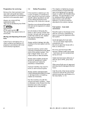
.... 4 MS 231, MS 231 C, MS 251, MS 251 C Always replace damaged parts. The specifications must be maintained when tightening down screws, nuts and other fasteners in the instruction manual. Avoid damaging the hose barb - do not use original STIHL replacement parts. Do not re-use fuel hoses after working on the fuel system and the engine. Preparations for servicing Remove the chain sprocket cover, saw chain and guide bar before re-installing - Storing and disposing of oils and fuels Collect fuel or lubricating oil...
.... 4 MS 231, MS 231 C, MS 251, MS 251 C Always replace damaged parts. The specifications must be maintained when tightening down screws, nuts and other fasteners in the instruction manual. Avoid damaging the hose barb - do not use original STIHL replacement parts. Do not re-use fuel hoses after working on the fuel system and the engine. Preparations for servicing Remove the chain sprocket cover, saw chain and guide bar before re-installing - Storing and disposing of oils and fuels Collect fuel or lubricating oil...
Instruction Manual
Page 8
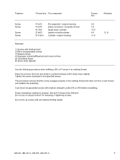
... 242 or 243 before reinstalling. MS 231, MS 231 C, MS 251, MS 251 C 7 Fastener Thread size For component Torque Nm Remarks Screw Screw Screw Screw P 4x12 P 4x10 M 10x1 D 4x20 D 5.3x41 Pre-separator / engine housing Elbow connector / air guide shroud Spark plug / cylinder Ignition module/cylinder Cylinder / engine housing 2.0 1.6 12.0 4.5 11.0 1), 3) Remarks: 1) Screws with binding head 2) Micro-encapsulated screws 3) Waxed screws 4) Degrease crankshaft/flywheel and mount oil-free Q) QuickStop Super B) Quick chain adjuster Use the following procedure when refitting a DG...
... 242 or 243 before reinstalling. MS 231, MS 231 C, MS 251, MS 251 C 7 Fastener Thread size For component Torque Nm Remarks Screw Screw Screw Screw P 4x12 P 4x10 M 10x1 D 4x20 D 5.3x41 Pre-separator / engine housing Elbow connector / air guide shroud Spark plug / cylinder Ignition module/cylinder Cylinder / engine housing 2.0 1.6 12.0 4.5 11.0 1), 3) Remarks: 1) Screws with binding head 2) Micro-encapsulated screws 3) Waxed screws 4) Degrease crankshaft/flywheel and mount oil-free Q) QuickStop Super B) Quick chain adjuster Use the following procedure when refitting a DG...

Instruction Manual
Page 13
... difficult to carrier Spring in spring housing not Attach spring loop to carrier attached to pull - models with ErgoStart Starter rope is Fit new pawl worn Spring clip on pawl fatigued Fit new spring clip Spring clip installed wrong Install spring clip correctly Guide pegs on pawls or pawls themselves are worn Fit new pawls Torsion springs on flywheel fatigued, pawls worn or sticking Clean seats on pawls or replace pawls and torsion...
... difficult to carrier Spring in spring housing not Attach spring loop to carrier attached to pull - models with ErgoStart Starter rope is Fit new pawl worn Spring clip on pawl fatigued Fit new spring clip Spring clip installed wrong Install spring clip correctly Guide pegs on pawls or pawls themselves are worn Fit new pawls Torsion springs on flywheel fatigued, pawls worn or sticking Clean seats on pawls or replace pawls and torsion...

Instruction Manual
Page 15
... recurring, check air filter Fuel/oil mixture - too much oil Use correct mixture of fuel and oil Incorrect air gap between ignition Set air gap correctly module and flywheel Flywheel cracked or damaged or pole shoes have turned blue Install new flywheel Ignition timing wrong, flywheel out of the spark plug, clean or replace spark plug if necessary. 14 MS 231, MS 231 C, MS 251, MS 251 C Check operation of adjustment - key in flywheel has sheared off Install new flywheel Weak magnetization in ignition lead or short circuit. 3.5 Ignition System Condition Engine runs roughly...
... recurring, check air filter Fuel/oil mixture - too much oil Use correct mixture of fuel and oil Incorrect air gap between ignition Set air gap correctly module and flywheel Flywheel cracked or damaged or pole shoes have turned blue Install new flywheel Ignition timing wrong, flywheel out of the spark plug, clean or replace spark plug if necessary. 14 MS 231, MS 231 C, MS 251, MS 251 C Check operation of adjustment - key in flywheel has sheared off Install new flywheel Weak magnetization in ignition lead or short circuit. 3.5 Ignition System Condition Engine runs roughly...
Instruction Manual
Page 17
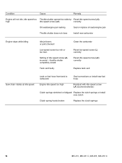
... Reset idle speed screw (LA) correctly Replace tank vent Saw chain rotates at idle speed Leak on fuel hose from tank to carburetor Seal connections or install new fuel hose Engine idle speed too high Readjust with idle speed screw LA (counterclockwise) Clutch springs stretched or fatigued Replace the clutch springs or install new clutch Clutch spring hooks broken Replace the clutch springs 16 MS 231, MS 231 C, MS 251, MS 251 C Condition Cause Remedy Engine will not idle, idle speed too Throttle shutter opened too wide by Reset idle speed screw (LA) high idle speed screw (LA...
... Reset idle speed screw (LA) correctly Replace tank vent Saw chain rotates at idle speed Leak on fuel hose from tank to carburetor Seal connections or install new fuel hose Engine idle speed too high Readjust with idle speed screw LA (counterclockwise) Clutch springs stretched or fatigued Replace the clutch springs or install new clutch Clutch spring hooks broken Replace the clutch springs 16 MS 231, MS 231 C, MS 251, MS 251 C Condition Cause Remedy Engine will not idle, idle speed too Throttle shutter opened too wide by Reset idle speed screw (LA) high idle speed screw (LA...
Instruction Manual
Page 19
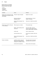
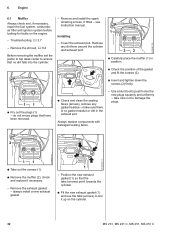
... housing 18 MS 231, MS 231 C, MS 251, MS 251 C Air inlets in fan housing blocked or cooling fins on the engine: - Engine does not deliver full power Piston rings worn or broken or runs erratically Muffler / spark arresting screen carbonized Air filter dirty Fuel hose kinked or torn Intake manifold damaged / bore blocked Fit new piston rings Clean the muffler (inlet and exhaust), replace spark arresting screen, replace muffler if necessary Clean or replace air filter Fit new hose or position it free...
... housing 18 MS 231, MS 231 C, MS 251, MS 251 C Air inlets in fan housing blocked or cooling fins on the engine: - Engine does not deliver full power Piston rings worn or broken or runs erratically Muffler / spark arresting screen carbonized Air filter dirty Fuel hose kinked or torn Intake manifold damaged / bore blocked Fit new piston rings Clean the muffler (inlet and exhaust), replace spark arresting screen, replace muffler if necessary Clean or replace air filter Fit new hose or position it free...
Instruction Manual
Page 24
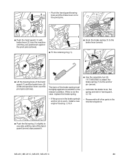
Lubricate the brake lever, flat spring and slot in the brake spring's anchor pin is not the case, replace the brake spring. - MS 231, MS 231 C, MS 251, MS 251 C 23 Reassemble all other parts in the relaxed condition. - If this is worn, install a new engine housing, b 6.6 2310RA028 TG : Use the assembly tool (2) 1117 890 0900 to attach the brake spring (1) to one another in the reverse sequence. 2310RA026 TG : Push the flat spring (1) slightly to the anchor...
Lubricate the brake lever, flat spring and slot in the brake spring's anchor pin is not the case, replace the brake spring. - MS 231, MS 231 C, MS 251, MS 251 C 23 Reassemble all other parts in the relaxed condition. - If this is worn, install a new engine housing, b 6.6 2310RA028 TG : Use the assembly tool (2) 1117 890 0900 to attach the brake spring (1) to one another in the reverse sequence. 2310RA026 TG : Push the flat spring (1) slightly to the anchor...
Instruction Manual
Page 25
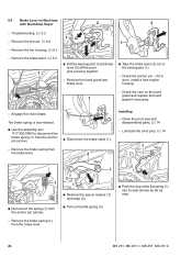
... TG 24 MS 231, MS 231 C, MS 251, MS 251 C Check the cam on Machines with QuickStop Super 2 2 - Remove the brake spring (1) from the anchor pin (arrow). - Remove the brake band, b 5.2 1 1 TOP : Pull the hand guard (1) and brake lever (2) off the pivot pins (arrows) together. - The brake spring is worn, install a new engine housing. - Remove the brake spring from the anchor pin (arrow). : Disconnect the brake cable (1). - TOP 2310RA031 TG - Check the anchor pin - if it is now relaxed. : Use the assembly tool 1117 890...
... TG 24 MS 231, MS 231 C, MS 251, MS 251 C Check the cam on Machines with QuickStop Super 2 2 - Remove the brake spring (1) from the anchor pin (arrow). - Remove the brake band, b 5.2 1 1 TOP : Pull the hand guard (1) and brake lever (2) off the pivot pins (arrows) together. - The brake spring is worn, install a new engine housing. - Remove the brake spring from the anchor pin (arrow). : Disconnect the brake cable (1). - TOP 2310RA031 TG - Check the anchor pin - if it is now relaxed. : Use the assembly tool 1117 890...

Instruction Manual
Page 27
... may be depressed without the brake lever moving. Free travel - Adjust the brake cable, b 5.4.1 - Checking condition and free travel is in hand guard, b 14 - 2 1 1 TOP 1 2310RA042 TG 2310RA031 TG 2310RA044 TG TOP : Attach the spring (1) to the brake lever (arrow) so that position. Release the lockout lever. - If this is visible. : Attach the spring (1) to the anchor pin (2). : Use the assembly tool 1117 890 0900 to the brake lever (arrow). 26 MS 231, MS 231 C, MS 251, MS 251 C Troubleshooting, b 3.2 -
... may be depressed without the brake lever moving. Free travel - Adjust the brake cable, b 5.4.1 - Checking condition and free travel is in hand guard, b 14 - 2 1 1 TOP 1 2310RA042 TG 2310RA031 TG 2310RA044 TG TOP : Attach the spring (1) to the brake lever (arrow) so that position. Release the lockout lever. - If this is visible. : Attach the spring (1) to the anchor pin (2). : Use the assembly tool 1117 890 0900 to the brake lever (arrow). 26 MS 231, MS 231 C, MS 251, MS 251 C Troubleshooting, b 3.2 -
Instruction Manual
Page 28
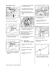
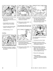
Loosen and lower the tank TOP housing, b 12.11.2 1 - Check the brake cable (1) and retainer (2), replace if necessary MS 231, MS 231 C, MS 251, MS 251 C 27 The brake band (1) must locate snugly against engine housing (arrows) and the clutch drum must rotate freely. 2 1 - Turn adjusting screw counter- clockwise to increase free travel. 1 1 - Remove the carburetor, b 12.5 - Turn adjusting screw clockwise to reduce free travel on the brake cable retainer. 1 2 : Use 6mm open end wrench the set free travel . : When the setting is correct...
Loosen and lower the tank TOP housing, b 12.11.2 1 - Check the brake cable (1) and retainer (2), replace if necessary MS 231, MS 231 C, MS 251, MS 251 C 27 The brake band (1) must locate snugly against engine housing (arrows) and the clutch drum must rotate freely. 2 1 - Turn adjusting screw counter- clockwise to increase free travel. 1 1 - Remove the carburetor, b 12.5 - Turn adjusting screw clockwise to reduce free travel on the brake cable retainer. 1 2 : Use 6mm open end wrench the set free travel . : When the setting is correct...
Instruction Manual
Page 33
... necessary, repair the fuel system, carburetor, air filter and ignition system before looking for faults on the cylinder. 32 MS 231, MS 231 C, MS 251, MS 251 C Remove any gasket residue - 6. take care not to push home the new plugs squarely and uniformly - Remove the exhaust gasket - do not re-use the tabs (arrows) to line it up on the engine. - always install a new exhaust gasket. 1 - Remove and install the spark arresting screen, if fitted - Troubleshooting, b 3.7 -
... necessary, repair the fuel system, carburetor, air filter and ignition system before looking for faults on the cylinder. 32 MS 231, MS 231 C, MS 251, MS 251 C Remove any gasket residue - 6. take care not to push home the new plugs squarely and uniformly - Remove the exhaust gasket - do not re-use the tabs (arrows) to line it up on the engine. - always install a new exhaust gasket. 1 - Remove and install the spark arresting screen, if fitted - Troubleshooting, b 3.7 -
Instruction Manual
Page 47
... TG 2310RA121 TG 2 2 1 : Pull the short circuit wire (1) and ground wire (2) out of the ignition module and the flywheel magnet poles. 2 - Check the spark plug boot and replace if necessary, b 7.5 : Hold the retainer (1) against the setting gauge and tighten down the screws (2) firmly - do not tighten down yet. Check ignition lead, replace ignition module if necessary - Troubleshooting, b 3.5 Installing 1 1 2 N S 1 : Position the retainer (1) against the cylinder and attach its pegs to...
... TG 2310RA121 TG 2 2 1 : Pull the short circuit wire (1) and ground wire (2) out of the ignition module and the flywheel magnet poles. 2 - Check the spark plug boot and replace if necessary, b 7.5 : Hold the retainer (1) against the setting gauge and tighten down the screws (2) firmly - do not tighten down yet. Check ignition lead, replace ignition module if necessary - Troubleshooting, b 3.5 Installing 1 1 2 N S 1 : Position the retainer (1) against the cylinder and attach its pegs to...

Instruction Manual
Page 49
... MS 231, MS 231 C, MS 251, MS 251 C If a spark is visible in the window (3), the ignition system is visible in a safe place. Installing 165RA184 TG 165RA188 TG 23 4 - If no spark is in the tester's window (3). High voltage - Remove the spark plug boot and pull the ignition lead out of the spark plug boot. - risk of electric shock. : Use suitable pliers to pull the leg spring out of the guides, b 7.3 - The engine may start...
... MS 231, MS 231 C, MS 251, MS 251 C If a spark is visible in the window (3), the ignition system is visible in a safe place. Installing 165RA184 TG 165RA188 TG 23 4 - If no spark is in the tester's window (3). High voltage - Remove the spark plug boot and pull the ignition lead out of the spark plug boot. - risk of electric shock. : Use suitable pliers to pull the leg spring out of the guides, b 7.3 - The engine may start...
Instruction Manual
Page 96
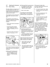
... high speed screw H (1) against its seat, open it 1 1/2 turns counterclockwise - MS 231, MS 231 C, MS 251, MS 251 C 95 the ignition module limits maximum engine speed to make the mixture any leaner - 12.7 Adjusting the Carburetor 12.7.1 Basic Setting The basic setting is necessary only if the high speed screw (H) or low speed screw (L) has to 3,300 rpm. 4. Check chain tension and adjust if necessary. - Adjust idle speed with a tachometer. Use the low speed screw (L) to set the engine speed again to be replaced or after removing...
... high speed screw H (1) against its seat, open it 1 1/2 turns counterclockwise - MS 231, MS 231 C, MS 251, MS 251 C 95 the ignition module limits maximum engine speed to make the mixture any leaner - 12.7 Adjusting the Carburetor 12.7.1 Basic Setting The basic setting is necessary only if the high speed screw (H) or low speed screw (L) has to 3,300 rpm. 4. Check chain tension and adjust if necessary. - Adjust idle speed with a tachometer. Use the low speed screw (L) to set the engine speed again to be replaced or after removing...
Instruction Manual
Page 97
... MS 251 C Check chain tension and adjust if necessary. - Check the air filter and clean or replace if necessary, b 12.1 Standard setting - Turn the low speed screw (L) slowly clockwise as far as a result of lack of the high speed screw H and the low speed screw L . Adjusting engine idle speed - Check standard setting. - Inspect the spark arresting screen (if fitted) and clean or replace if necessary, b 3.7 or b 6.1 2310RA285 TG - Warm up the engine. - Troubleshooting, b 3.6 - Shut off the engine. - Turn the idle speed screw (LA) clockwise until the chain starts running...
... MS 251 C Check chain tension and adjust if necessary. - Check the air filter and clean or replace if necessary, b 12.1 Standard setting - Turn the low speed screw (L) slowly clockwise as far as a result of lack of the high speed screw H and the low speed screw L . Adjusting engine idle speed - Check standard setting. - Inspect the spark arresting screen (if fitted) and clean or replace if necessary, b 3.7 or b 6.1 2310RA285 TG - Warm up the engine. - Troubleshooting, b 3.6 - Shut off the engine. - Turn the idle speed screw (LA) clockwise until the chain starts running...

Instruction Manual
Page 108
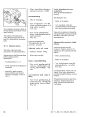
.... - Check operation - Install new fuel hoses. 1 : Position the fuel pump (1) so that the lug (3) points towards the recess (arrow). : Push the fuel pump (1) into the air guide shroud (2) until the tabs engage. 312 2310RA408 TG 2310RA406 TG 6 45 : Squeeze the tabs (arrows) together and pull out the manual fuel pump (1). - Install the carburetor, b 12.5 12.11.4 Manual Fuel Pump Installing - Check operation of manual fuel pump, b 12.11.4 - fuel must flow when the fuel pump is operated. - MS 231, MS 231 C, MS 251, MS 251 C 107 - Install the air guide...
.... - Check operation - Install new fuel hoses. 1 : Position the fuel pump (1) so that the lug (3) points towards the recess (arrow). : Push the fuel pump (1) into the air guide shroud (2) until the tabs engage. 312 2310RA408 TG 2310RA406 TG 6 45 : Squeeze the tabs (arrows) together and pull out the manual fuel pump (1). - Install the carburetor, b 12.5 12.11.4 Manual Fuel Pump Installing - Check operation of manual fuel pump, b 12.11.4 - fuel must flow when the fuel pump is operated. - MS 231, MS 231 C, MS 251, MS 251 C 107 - Install the air guide...

Instruction Manual
Page 111
... Removing and installing piston pin Adjusting air gap between the ignition module and flywheel Installing rewind spring Attaching springs Leakage Test Protecting the oil seal (clutch side) Installing oil seal (clutch side/ignition side) Spark plug 1) Protecting the oil seal (ignition side) Clamping machine to assembly stand Testing ignition system Testing ignition system 110 MS 231, MS 231 C, MS 251, MS 251 C Nipple - tightening down tool Part No. 5910 890 4000 Application Fitting electrical wires in guides Rem. Existing Special Tools No. 13. Special Servicing Tools...
... Removing and installing piston pin Adjusting air gap between the ignition module and flywheel Installing rewind spring Attaching springs Leakage Test Protecting the oil seal (clutch side) Installing oil seal (clutch side/ignition side) Spark plug 1) Protecting the oil seal (ignition side) Clamping machine to assembly stand Testing ignition system Testing ignition system 110 MS 231, MS 231 C, MS 251, MS 251 C Nipple - tightening down tool Part No. 5910 890 4000 Application Fitting electrical wires in guides Rem. Existing Special Tools No. 13. Special Servicing Tools...
Instruction Manual
Page 112
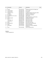
... Rem. MS 231, MS 231 C, MS 251, MS 251 C 111 Jaws (No. 3.1) - Removing bar mounting studs Removing flywheel Add-on clutch shoes Holding saw for releasing only. Sealing exhaust port for leakage test 0.5 to 18 Nm 6 to 80 Nm Installing hookless snap rings in piston Sleeve for installing tool 10 Adjusting the carburetor IS-P screws Detaching springs on for screwdriver (adjusting carburetor) Removing pickup body Remarks: 1) Use for repairs Removing oil seals Removing oil seals Removing oil seals Pull off...
... Rem. MS 231, MS 231 C, MS 251, MS 251 C 111 Jaws (No. 3.1) - Removing bar mounting studs Removing flywheel Add-on clutch shoes Holding saw for releasing only. Sealing exhaust port for leakage test 0.5 to 18 Nm 6 to 80 Nm Installing hookless snap rings in piston Sleeve for installing tool 10 Adjusting the carburetor IS-P screws Detaching springs on for screwdriver (adjusting carburetor) Removing pickup body Remarks: 1) Use for repairs Removing oil seals Removing oil seals Removing oil seals Pull off...


