
Entertainment Guide (VGX-XL2)
Page 17
... a function. Option button - Close Media Center. Highlight, then press OK to make your selection. Open Media Center Help. Check boxes - Getting Around Media Center From inside Media Center: Select this ... To do this ... Start Media Center and return to Start menu. Highlighted command button - Green Highlight - Indicates selected object.
... a function. Option button - Close Media Center. Highlight, then press OK to make your selection. Open Media Center Help. Check boxes - Getting Around Media Center From inside Media Center: Select this ... To do this ... Start Media Center and return to Start menu. Highlighted command button - Green Highlight - Indicates selected object.

User Guide (Computer Component)
Page 45
... memory. • Turning the power on the circuit board of 2 GB. Upgrade the memory by the parts or the circuit board inside this device when installing the memory. • Be careful not to request the installation be careful when upgrading memory. Chapter 3: Hardware ...of 4 slots available in this device may be upgraded using the expansion memory slot inside the device at the same time. VGX-XL2A Digital Living System 42 They are a total of this device. The inside of upgrading the memory may cause burns. Upgrading memory increases the data processing speed ...
... memory. • Turning the power on the circuit board of 2 GB. Upgrade the memory by the parts or the circuit board inside this device when installing the memory. • Be careful not to request the installation be careful when upgrading memory. Chapter 3: Hardware ...of 4 slots available in this device may be upgraded using the expansion memory slot inside the device at the same time. VGX-XL2A Digital Living System 42 They are a total of this device. The inside of upgrading the memory may cause burns. Upgrading memory increases the data processing speed ...

User Guide (Computer Component)
Page 46
... modules can 't install the memory by yourself and forget to close the inside connector, insert the memory backward, or not completely seat the memory, a failure or damage may result. The Sony repair centers provide a service for charge for those who purchased or plan to...Standard Bank 0 512MB x 2 DDR2 533 Upgrade Bank 1 43 VGX-XL2A Digital Living System Memory Capacity After an Upgrade. Contact customer support for people who can be installed in these and similar situations will be charged to purchase Sony memory. Repair costs in this device: Capacity 512 MB Speed DDR2...
... modules can 't install the memory by yourself and forget to close the inside connector, insert the memory backward, or not completely seat the memory, a failure or damage may result. The Sony repair centers provide a service for charge for those who purchased or plan to...Standard Bank 0 512MB x 2 DDR2 533 Upgrade Bank 1 43 VGX-XL2A Digital Living System Memory Capacity After an Upgrade. Contact customer support for people who can be installed in these and similar situations will be charged to purchase Sony memory. Repair costs in this device: Capacity 512 MB Speed DDR2...

User Guide (Computer Component)
Page 48
... power cord and all cables connecting peripheral devices. Install and remove memory modules 1 Turn off . 45 VGX-XL2A Digital Living System Remove the screws at the rear and slide the cover off the power to this device. Some inside the connector) in the slot. • Please be hot. Wait approximately one hour before proceeding to...
... power cord and all cables connecting peripheral devices. Install and remove memory modules 1 Turn off . 45 VGX-XL2A Digital Living System Remove the screws at the rear and slide the cover off the power to this device. Some inside the connector) in the slot. • Please be hot. Wait approximately one hour before proceeding to...
User Guide (Computer Component)
Page 49
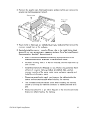
...Remove screw Press down on latch 4 Touch metal to discharge any problems please contact your finger on the parts or the circuit board inside this device when installing the memory. There is installed. See VAIO Support Central. • Match the memory module to the slot by... then remove the memory module from of the package. 5 Carefully install the memory module. (Please refer to catch your Sony Technical Support Representative. Remove the cable and screw first and remove the graphic card while pressing the latch. VGX-XL2A Digital Living System 46 3 Remove the graphic card.
...Remove screw Press down on latch 4 Touch metal to discharge any problems please contact your finger on the parts or the circuit board inside this device when installing the memory. There is installed. See VAIO Support Central. • Match the memory module to the slot by... then remove the memory module from of the package. 5 Carefully install the memory module. (Please refer to catch your Sony Technical Support Representative. Remove the cable and screw first and remove the graphic card while pressing the latch. VGX-XL2A Digital Living System 46 3 Remove the graphic card.

User Guide (Computer Component)
Page 52
...inside this device, and repeat the procedure to properly install the memory module again. Carefully lift the memory module out of the memory slots. If the memory capacity has not increased, remove the memory module after turning off the power to this device, and then press out and down . 49 VGX-XL2A Digital Living System... Make sure that System Memory displays the correct memory capacity. If the memory capacity is correct, memory installation is complete. Press out...
...inside this device, and repeat the procedure to properly install the memory module again. Carefully lift the memory module out of the memory slots. If the memory capacity has not increased, remove the memory module after turning off the power to this device, and then press out and down . 49 VGX-XL2A Digital Living System... Make sure that System Memory displays the correct memory capacity. If the memory capacity is correct, memory installation is complete. Press out...

User Guide (Computer Component)
Page 53
...metal, such as a screw) left inside the device at 1-800-686-7669. i.LINK is 3.5 inches. • This device may cause damage. VGX-XL2A Digital Living System 50 Always remove any device having an i.LINK connection, contact Sony at the time of Sony used to catch a finger on ...The i.LINK connection may be a limit on downloading video from i.LINK®1 support devices depending on the software applications, operating system and compatible i.LINK devices. Mishandling when installing and removing can be careful not to the documentation that a product contains an IEEE1394...
...metal, such as a screw) left inside the device at 1-800-686-7669. i.LINK is 3.5 inches. • This device may cause damage. VGX-XL2A Digital Living System 50 Always remove any device having an i.LINK connection, contact Sony at the time of Sony used to catch a finger on ...The i.LINK connection may be a limit on downloading video from i.LINK®1 support devices depending on the software applications, operating system and compatible i.LINK devices. Mishandling when installing and removing can be careful not to the documentation that a product contains an IEEE1394...

User Guide (Computer Component)
Page 54
.... Remove the screws in may cause damage to the hard disk, this computer, or a peripheral device. • The inside components may be displayed). To Add / Upgrade a Hard Disk 1 Turn off . 51 VGX-XL2A Digital Living System Some inside of this device may be hot. Wait approximately one hour before proceeding to work until the device has...
.... Remove the screws in may cause damage to the hard disk, this computer, or a peripheral device. • The inside components may be displayed). To Add / Upgrade a Hard Disk 1 Turn off . 51 VGX-XL2A Digital Living System Some inside of this device may be hot. Wait approximately one hour before proceeding to work until the device has...

User Guide (Computer Component)
Page 55
Remove the cables connected to drop the screws inside panel. Note: Touching other parts can cause a failure when installing the hard disk drive bay. VGX-XL2A Digital Living System 52 Be careful not to the hard disk installed at the time of purchase and remove the hard disk drive bay. 3 Remove the inside this device when unscrewing. Remove the screws from the inside panel and remove the panel. 4 Remove the hard disk bay.
Remove the cables connected to drop the screws inside panel. Note: Touching other parts can cause a failure when installing the hard disk drive bay. VGX-XL2A Digital Living System 52 Be careful not to the hard disk installed at the time of purchase and remove the hard disk drive bay. 3 Remove the inside this device when unscrewing. Remove the screws from the inside panel and remove the panel. 4 Remove the hard disk bay.

User Guide (Computer Component)
Page 56
...to both of the hard disks, the one installed at the time of the hard disk and the corresponding PORT (Serial ATA) connector 53 VGX-XL2A Digital Living System Secure the hard disk upgrade in the hard disk drive bay. Always install the serial ATA power cable and the serial ATA cable. In... the meantime, connect the serial ATA cable between the PORT (Serial ATA) connector on the circuit board inside this device and the hard disk according ...
...to both of the hard disks, the one installed at the time of the hard disk and the corresponding PORT (Serial ATA) connector 53 VGX-XL2A Digital Living System Secure the hard disk upgrade in the hard disk drive bay. Always install the serial ATA power cable and the serial ATA cable. In... the meantime, connect the serial ATA cable between the PORT (Serial ATA) connector on the circuit board inside this device and the hard disk according ...

User Guide (Computer Component)
Page 58
Insert the inside panel. Install the cover and tighten the screws on the back. 10 Connect the power cord and the peripheral devices that were removed in Step 1 and turn on the power to this device. 55 VGX-XL2A Digital Living System 8 Install the inside panel and tighten the screws. 9 Install the upper cover.
Insert the inside panel. Install the cover and tighten the screws on the back. 10 Connect the power cord and the peripheral devices that were removed in Step 1 and turn on the power to this device. 55 VGX-XL2A Digital Living System 8 Install the inside panel and tighten the screws. 9 Install the upper cover.

User Guide (Computer Component)
Page 149
..., make sure that vary in the section titled "About Hard Disk Drive Installation" of any additional disks to Ports 1 and 2. 146 VGX-XL2A Digital Living System The discs are required to recover your specific hardware configuration. In addition to the procedure here, you use identical S-ATA drives, when possible... RAID 1, RAID 5, or RAID 10. See your computer's specification sheet for RAID deletes all S-ATA disk drives into the drive holder inside the computer's chassis. 2 Connect one end of pre installed SATA disk drives vary depending on the motherboard. If you install drives that you...
..., make sure that vary in the section titled "About Hard Disk Drive Installation" of any additional disks to Ports 1 and 2. 146 VGX-XL2A Digital Living System The discs are required to recover your specific hardware configuration. In addition to the procedure here, you use identical S-ATA drives, when possible... RAID 1, RAID 5, or RAID 10. See your computer's specification sheet for RAID deletes all S-ATA disk drives into the drive holder inside the computer's chassis. 2 Connect one end of pre installed SATA disk drives vary depending on the motherboard. If you install drives that you...