
Operating Instructions
Page 1
3-289-200-11(1) Multi Channel AV Receiver Operating Instructions STR-DG920 ©2008 Sony Corporation
3-289-200-11(1) Multi Channel AV Receiver Operating Instructions STR-DG920 ©2008 Sony Corporation
Operating Instructions
Page 2
... or moisture. Record the serial number in cabinet. Install this equipment does cause harmful interference to radio or television reception, which the receiver is intended to alert the user to the presence of uninsulated "dangerous voltage" within the product's enclosure that to the point of ...be determined by one or more of trouble. CAUTION You are cautioned that interference will not occur in this manual could void your Sony dealer regarding this apparatus to radio communications. Owner's Record The model and serial numbers are located on the apparatus. Do not install ...
... or moisture. Record the serial number in cabinet. Install this equipment does cause harmful interference to radio or television reception, which the receiver is intended to alert the user to the presence of uninsulated "dangerous voltage" within the product's enclosure that to the point of ...be determined by one or more of trouble. CAUTION You are cautioned that interference will not occur in this manual could void your Sony dealer regarding this apparatus to radio communications. Owner's Record The model and serial numbers are located on the apparatus. Do not install ...
Operating Instructions
Page 3
... Reserved. This product is shown on the upper right portion of the receiver you purchased is manufactured under license from Dolby Laboratories. iPod is provided by Sony Corporation is used for illustration purposes unless stated otherwise. "x.v.Color" and ...receiver is a trademark of such marks by MORISAWA & COMPANY LTD. DTS is a registered trademark of the font also belongs to the area code, are the trademarks of MORISAWA & COMPANY LTD., and the copyright of XM Satellite Radio Inc. All rights reserved. These names are clearly indicated in the text, for model STR...
... Reserved. This product is shown on the upper right portion of the receiver you purchased is manufactured under license from Dolby Laboratories. iPod is provided by Sony Corporation is used for illustration purposes unless stated otherwise. "x.v.Color" and ...receiver is a trademark of such marks by MORISAWA & COMPANY LTD. DTS is a registered trademark of the font also belongs to the area code, are the trademarks of MORISAWA & COMPANY LTD., and the copyright of XM Satellite Radio Inc. All rights reserved. These names are clearly indicated in the text, for model STR...
Operating Instructions
Page 4
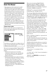
...the audio components.........19 4b: Connecting the video components ........24 5: Connecting the antennas (aerials 34 6: Preparing the receiver and the remote .....35 7: Operating the receiver using the GUI (Graphical User Interface 36 8: Selecting the speaker system 39 9: Calibrating the appropriate speaker settings ...74 Watching a DVD (One-Touch Play 75 Enjoying the TV sound from the speakers connected to the receiver (System Audio Control 76 Turning off the receiver with the TV (System Power Off 76 Other Operations Converting analog video input signals........ 77 Enjoying the...
...the audio components.........19 4b: Connecting the video components ........24 5: Connecting the antennas (aerials 34 6: Preparing the receiver and the remote .....35 7: Operating the receiver using the GUI (Graphical User Interface 36 8: Selecting the speaker system 39 9: Calibrating the appropriate speaker settings ...74 Watching a DVD (One-Touch Play 75 Enjoying the TV sound from the speakers connected to the receiver (System Audio Control 76 Turning off the receiver with the TV (System Power Off 76 Other Operations Converting analog video input signals........ 77 Enjoying the...
Operating Instructions
Page 6
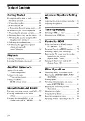
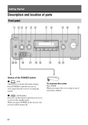
...cover Press PUSH. When you remove the cover, keep it to turn the receiver on or set it out of parts Front panel 1 23 4 5 6 78 9 q; You cannot turn the receiver on the receiver, the receiver will be turned off (initial setting). qa ON/STANDBY POWER SPEAKERS (OFF/A/B/A+B)... TONE MODE TONE TUNING MODE TUNING PHONES VIDEO 2 IN/PORTABLE AV IN VIDEO L AUDIO R AUTO CAL MIC MULTI CHANNEL DECODING DISPLAY ...
...cover Press PUSH. When you remove the cover, keep it to turn the receiver on or set it out of parts Front panel 1 23 4 5 6 78 9 q; You cannot turn the receiver on the receiver, the receiver will be turned off (initial setting). qa ON/STANDBY POWER SPEAKERS (OFF/A/B/A+B)... TONE MODE TONE TUNING MODE TUNING PHONES VIDEO 2 IN/PORTABLE AV IN VIDEO L AUDIO R AUTO CAL MIC MULTI CHANNEL DECODING DISPLAY ...
Operating Instructions
Page 7
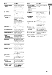
...surround speakers. Adjusts the tonal quality (bass/treble level) of selectable items appears here (page 85). F Remote sensor Receives signals from remote commander. R VIDEO 2 IN/ PORTABLE AV IN jacks Connects to the supplied optimizer microphone for the Auto Calibration function (page 40). Q AUTO CAL MIC jack ...level of the display (page 93). to playback (page 44). K MASTER VOLUME Turn to select bass or treble level, then turn the receiver on the display (page 84, 113). L INPUT SELECTOR Turn to select the input source to adjust the level (page 90). MOVIE MUSIC...
...surround speakers. Adjusts the tonal quality (bass/treble level) of selectable items appears here (page 85). F Remote sensor Receives signals from remote commander. R VIDEO 2 IN/ PORTABLE AV IN jacks Connects to the supplied optimizer microphone for the Auto Calibration function (page 40). Q AUTO CAL MIC jack ...level of the display (page 93). to playback (page 44). K MASTER VOLUME Turn to select bass or treble level, then turn the receiver on the display (page 84, 113). L INPUT SELECTOR Turn to select the input source to adjust the level (page 90). MOVIE MUSIC...
Operating Instructions
Page 8
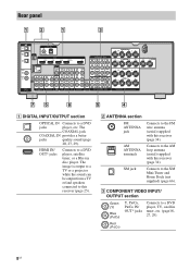
... to a DVD player, satellite tuner, or a Blu-ray disc player. HDMI IN/ OUT* jacks Connects to the FM wire antenna (aerial) supplied with this receiver (page 34). AM ANTENNA terminals Connects to a DVD player, TV, satellite tuner, etc. (page18, 27, 29). C COMPONENT VIDEO INPUT/ OUTPUT section Green ...(Y) Blue (PB/CB) Y, PB/CB, PR/CR IN/ OUT* jacks Connects to the AM loop antenna (aerial) supplied with this receiver (page 25). The COAXIAL jack COAXIAL IN provides a better jacks quality sound (page 20, 27, 29). Red (PR/CR) 8US The image is...
... to a DVD player, satellite tuner, or a Blu-ray disc player. HDMI IN/ OUT* jacks Connects to the FM wire antenna (aerial) supplied with this receiver (page 34). AM ANTENNA terminals Connects to a DVD player, TV, satellite tuner, etc. (page18, 27, 29). C COMPONENT VIDEO INPUT/ OUTPUT section Green ...(Y) Blue (PB/CB) Y, PB/CB, PR/CR IN/ OUT* jacks Connects to the AM loop antenna (aerial) supplied with this receiver (page 25). The COAXIAL jack COAXIAL IN provides a better jacks quality sound (page 20, 27, 29). Red (PR/CR) 8US The image is...
Operating Instructions
Page 9
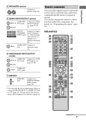
... Yellow OUT* jacks G DMPORT DMPORT jack Connects to a DIGITAL MEDIA PORT adapter (page 20). * You can use the supplied remote to operate the receiver and to control the Sony audio/video components that the remote is assigned to a Super Audio CD player, etc. (page 18, 20, 23). CATEGORY + .< > < TUNING... - with an analog audio jack for 7.1 channel or 5.1 channel sound (page 22). RM-AAP023 wh wg wf wd ws wa ?/1 THEATER RM SET UP AV ?/1 ...
... Yellow OUT* jacks G DMPORT DMPORT jack Connects to a DIGITAL MEDIA PORT adapter (page 20). * You can use the supplied remote to operate the receiver and to control the Sony audio/video components that the remote is assigned to a Super Audio CD player, etc. (page 18, 20, 23). CATEGORY + .< > < TUNING... - with an analog audio jack for 7.1 channel or 5.1 channel sound (page 22). RM-AAP023 wh wg wf wd ws wa ?/1 THEATER RM SET UP AV ?/1 ...
Operating Instructions
Page 10
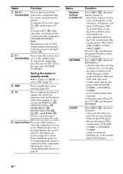
...that the remote is set it will turn off the receiver and other components (SYSTEM STANDBY). B ?/1 Press to turn the receiver on or (on or off all components, press ?/1 and AV ?/1 (A) at the same time, it to operate. When "Control for Sony TVs only. D TV Press to "OFF" (page...then press ENT/MEM. When you press the input buttons (E). C AMP Press to control non-Sony components following the steps in standby mode. You can program the remote to enable the receiver operation (page 89). Press 0/10 to perform menu operations for HDMI" is programmed to the ...
...that the remote is set it will turn off the receiver and other components (SYSTEM STANDBY). B ?/1 Press to turn the receiver on or (on or off all components, press ?/1 and AV ?/1 (A) at the same time, it to operate. When "Control for Sony TVs only. D TV Press to "OFF" (page...then press ENT/MEM. When you press the input buttons (E). C AMP Press to control non-Sony components following the steps in standby mode. You can program the remote to enable the receiver operation (page 89). Press 0/10 to perform menu operations for HDMI" is programmed to the ...
Operating Instructions
Page 11
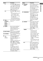
...Sony TV, press TV (D) and then press HOME/ MENU. H NIGHT MODE Press to perform menu operations. Then, use V/v/B/b (J) and (J) to activate the NIGHT MODE function (page 56). continued 11US Press SHIFT (X), then press -/-- A.F.D. Name K OPTIONS TOOLS L HOME/MENU M ./> m/M N* Function Press to display and select items from the option menus for receiver...select channel numbers of the VCR or satellite tuner. J , V/v/B/b After pressing AMP (C), press MENU (L) for receiver, DVD player, Blu-ray disc player or satellite tuner. Press to display the menu to - Press to operate ...
...Sony TV, press TV (D) and then press HOME/ MENU. H NIGHT MODE Press to perform menu operations. Then, use V/v/B/b (J) and (J) to activate the NIGHT MODE function (page 56). continued 11US Press SHIFT (X), then press -/-- A.F.D. Name K OPTIONS TOOLS L HOME/MENU M ./> m/M N* Function Press to display and select items from the option menus for receiver...select channel numbers of the VCR or satellite tuner. J , V/v/B/b After pressing AMP (C), press MENU (L) for receiver, DVD player, Blu-ray disc player or satellite tuner. Press to display the menu to - Press to operate ...
Operating Instructions
Page 13
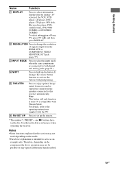
...mode when the same components are connected to set up the button. It changes the remote button function to serve as references when operating the receiver. Getting Started Name Function U DISPLAY Press to change the resolution of signals output from the speakers connected to light up the remote. *... function if your TV is intended to activate the buttons with the TV. V RESOLUTION Press to select information displayed in this receiver automatically. Notes • Some functions explained in the display, TV screen of Sony TV, press TV (D) and then press DISPLAY.
...mode when the same components are connected to set up the button. It changes the remote button function to serve as references when operating the receiver. Getting Started Name Function U DISPLAY Press to change the resolution of signals output from the speakers connected to light up the remote. *... function if your TV is intended to activate the buttons with the TV. V RESOLUTION Press to select information displayed in this receiver automatically. Notes • Some functions explained in the display, TV screen of Sony TV, press TV (D) and then press DISPLAY.
Operating Instructions
Page 14
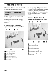
... enjoy theater-like multi channel surround sound requires five speakers (two front speakers, a center speaker, and two surround speakers) and a subwoofer (5.1 channel). 1: Installing speakers This receiver allows you connect one subwoofer).
... enjoy theater-like multi channel surround sound requires five speakers (two front speakers, a center speaker, and two surround speakers) and a subwoofer (5.1 channel). 1: Installing speakers This receiver allows you connect one subwoofer).
Operating Instructions
Page 17
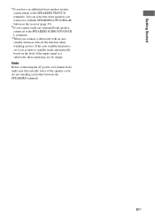
... to on, it to the SPEAKERS SURROUND BACK L terminals. You can select the front speakers you connect a subwoofer with the SPEAKERS (OFF/A/B/A+B) button on the receiver (page 39). b)If you have an additional front speaker system, connect them to the SPEAKERS FRONT B terminals. Getting Started a)If you connect only one surround...
... to on, it to the SPEAKERS SURROUND BACK L terminals. You can select the front speakers you connect a subwoofer with the SPEAKERS (OFF/A/B/A+B) button on the receiver (page 39). b)If you have an additional front speaker system, connect them to the SPEAKERS FRONT B terminals. Getting Started a)If you connect only one surround...
Operating Instructions
Page 18
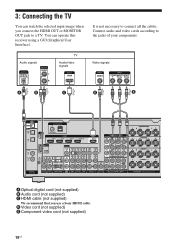
Connect audio and video cords according to connect all the cables. 3: Connecting the TV You can operate this receiver using a GUI (Graphical User Interface). Audio signals TV Audio/video signals Video signals A B C D E TV OPTICAL IN ANTENNA FM AM OPTICAL VIDEO 1 IN SAT IN XM ... the jacks of your components. D Video cord (not supplied) E Component video cord (not supplied) 18US You can watch the selected input image when you use a Sony HDMI cable.
Connect audio and video cords according to connect all the cables. 3: Connecting the TV You can operate this receiver using a GUI (Graphical User Interface). Audio signals TV Audio/video signals Video signals A B C D E TV OPTICAL IN ANTENNA FM AM OPTICAL VIDEO 1 IN SAT IN XM ... the jacks of your components. D Video cord (not supplied) E Component video cord (not supplied) 18US You can watch the selected input image when you use a Sony HDMI cable.
Operating Instructions
Page 19
... TV IN jacks of the connection between either "Fixed" or "Variable". • All the digital audio jacks are being output to a TV via the receiver. Before you connect the audio output jack of the TV to "4b: Connecting the video components" (page 24) or "5: Connecting the antennas (aerials)" ...video signals" (page 32). • The sound of the TV is transmitted. • Depending on , neither video nor audio is output from the receiver. • When connecting optical digital cords, insert the plugs straight in until they click into place. • Do not bend or tie optical digital cords...
... TV IN jacks of the connection between either "Fixed" or "Variable". • All the digital audio jacks are being output to a TV via the receiver. Before you connect the audio output jack of the TV to "4b: Connecting the video components" (page 24) or "5: Connecting the antennas (aerials)" ...video signals" (page 32). • The sound of the TV is transmitted. • Depending on , neither video nor audio is output from the receiver. • When connecting optical digital cords, insert the plugs straight in until they click into place. • Do not bend or tie optical digital cords...
Operating Instructions
Page 20
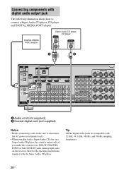
....1 kHz, 48 kHz, and 96 kHz sampling frequencies. 20US Refer to MULTI CHANNEL INPUT or SA-CD/CD IN jacks (analog input jack) on the receiver.
....1 kHz, 48 kHz, and 96 kHz sampling frequencies. 20US Refer to MULTI CHANNEL INPUT or SA-CD/CD IN jacks (analog input jack) on the receiver.
Operating Instructions
Page 21
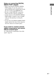
... DIGITAL MEDIA PORT adapter • When connecting the DIGITAL MEDIA PORT adapter, be sure the connector is inserted with care when placing or moving the receiver. • To disconnect the DIGITAL MEDIA PORT adapter, squeeze the sides of the DIGITAL MEDIA PORT adapter is fragile, be sure to connect several digital...
... DIGITAL MEDIA PORT adapter • When connecting the DIGITAL MEDIA PORT adapter, be sure the connector is inserted with care when placing or moving the receiver. • To disconnect the DIGITAL MEDIA PORT adapter, squeeze the sides of the DIGITAL MEDIA PORT adapter is fragile, be sure to connect several digital...
Operating Instructions
Page 22
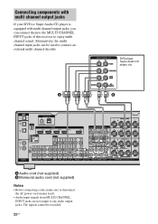
Alternatively, the multi channel input jacks can connect them to the MULTI CHANNEL INPUT jacks of this receiver to any audio output jacks. DVD player, Super Audio CD player, etc. Connecting components with multi channel output jacks If your DVD or Super Audio ...
Alternatively, the multi channel input jacks can connect them to the MULTI CHANNEL INPUT jacks of this receiver to any audio output jacks. DVD player, Super Audio CD player, etc. Connecting components with multi channel output jacks If your DVD or Super Audio ...
Operating Instructions
Page 24
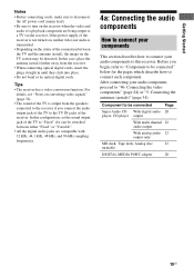
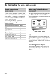
.... After connecting all your components, proceed to a TV via the receiver. Select the connection according to be connected The image quality depends on the receiver when the video and audio of the receiver is not turned on your components. Component to be connected" below ... of a playback component are being output to "5: Connecting the antennas (aerials)" (page 34). Converting video signals This receiver is transmitted. Refer to this receiver. 4b: Connecting the video components How to connect your components This section describes how to connect your video components to ...
.... After connecting all your components, proceed to a TV via the receiver. Select the connection according to be connected The image quality depends on the receiver when the video and audio of the receiver is not turned on your components. Component to be connected" below ... of a playback component are being output to "5: Connecting the antennas (aerials)" (page 34). Converting video signals This receiver is transmitted. Refer to this receiver. 4b: Connecting the video components How to connect your components This section describes how to connect your video components to ...
Operating Instructions
Page 25
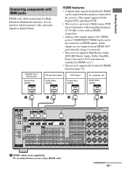
...interface which transmits video and audio signals in digital format. This signal supports Dolby Digital, DTS, and linear PCM. • The receiver can receive Multi Linear PCM (up -converted as HDMI signals. continued 25US Audio/video signals A A A A TV OPTICAL IN ANTENNA FM... CHANNEL INPUT SURROUND BACK R L SURROUND R L R FRONT B L FRONT A R L SPEAKERS A HDMI cable (not supplied) We recommend that you use a Sony HDMI cable. Getting Started Connecting components with an HDMI connection. • Analog video signals input to the VIDEO jack or COMPONENT VIDEO jacks can be...
...interface which transmits video and audio signals in digital format. This signal supports Dolby Digital, DTS, and linear PCM. • The receiver can receive Multi Linear PCM (up -converted as HDMI signals. continued 25US Audio/video signals A A A A TV OPTICAL IN ANTENNA FM... CHANNEL INPUT SURROUND BACK R L SURROUND R L R FRONT B L FRONT A R L SPEAKERS A HDMI cable (not supplied) We recommend that you use a Sony HDMI cable. Getting Started Connecting components with an HDMI connection. • Analog video signals input to the VIDEO jack or COMPONENT VIDEO jacks can be...


