
Limited Warranty (U.S. Only)
Page 1
..., Sony will repair or replace the Product, at its original packaging or packaging affording an equal degree of protection, to any authorized Sony service facility. This warranty does not cover customer instruction, installation, set up adjustments or signal reception problems. This warranty does not cover cosmetic damage or damage due to acts of God, accident, misuse, abuse, negligence, commercial use, or modification of sale or...
..., Sony will repair or replace the Product, at its original packaging or packaging affording an equal degree of protection, to any authorized Sony service facility. This warranty does not cover customer instruction, installation, set up adjustments or signal reception problems. This warranty does not cover cosmetic damage or damage due to acts of God, accident, misuse, abuse, negligence, commercial use, or modification of sale or...
Operating Instructions
Page 3
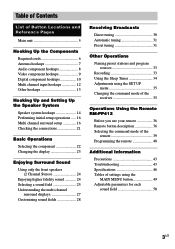
... cords 6 Antenna hookups 7 Audio component hookups 8 Video component hookups 9 Digital component hookups 10 Multi channel input hookups 12 Other hookups 13 Hooking Up and Setting Up the Speaker System Speaker system hookups 14 Performing initial setup operations ..... 16 Multi channel surround setup 16 Checking the connections 21 Basic Operations Selecting the component 22 Changing the display 23 Enjoying Surround Sound Using only the front speakers (2 Channel Stereo 24 Enjoying higher fidelity sound 24 Selecting a sound field 25 Understanding the multi channel surround displays...
... cords 6 Antenna hookups 7 Audio component hookups 8 Video component hookups 9 Digital component hookups 10 Multi channel input hookups 12 Other hookups 13 Hooking Up and Setting Up the Speaker System Speaker system hookups 14 Performing initial setup operations ..... 16 Multi channel surround setup 16 Checking the connections 21 Basic Operations Selecting the component 22 Changing the display 23 Enjoying Surround Sound Using only the front speakers (2 Channel Stereo 24 Enjoying higher fidelity sound 24 Selecting a sound field 25 Understanding the multi channel surround displays...
Operating Instructions
Page 4
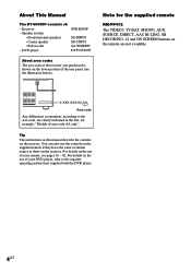
... the use of your DVD player, refer to the area code, are clearly indicated in the text, for the supplied remote RM-PP412 The VIDEO3, TV/SAT, PHONO, AUX, SOURCE, DIRECT, AAC BI-LING, SB DECODING, 12 and ON SCREEN buttons on the remote are not available. For details on the lower portion of : - Receiver - Speaker system • Front/surround speakers • Center speaker • Sub woofer - R L CENTER NCE USE 8-16Ω SURROUND...
... the use of your DVD player, refer to the area code, are clearly indicated in the text, for the supplied remote RM-PP412 The VIDEO3, TV/SAT, PHONO, AUX, SOURCE, DIRECT, AAC BI-LING, SB DECODING, 12 and ON SCREEN buttons on the remote are not available. For details on the lower portion of : - Receiver - Speaker system • Front/surround speakers • Center speaker • Sub woofer - R L CENTER NCE USE 8-16Ω SURROUND...
Operating Instructions
Page 9
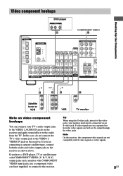
... video signals are connecting a separate satellite tuner, connect both the audio and video output jacks to the VIDEO 2 VIDEO IN jack on a separate bus from the TV. Hooking Up the Components Ç Ç Video component hookups DVD player OUTPUT AUDIO OUT R L VIDEO OUT B COMPONENT VIDEO H DIGITAL OPTICAL VIDEO 2 IN MD/ TAPE IN MD/ TAPE OUT CD/ SACD IN DVD IN COAXIAL L ANTENNA AM y FM 75Ω COAXIAL L CENTER MONITOR VIDEO IN VIDEO IN VIDEO OUT VIDEO IN VIDEO OUT S-VIDEO S-VIDEO IN IN L S-VIDEO S-VIDEO OUT IN L S-VIDEO OUT AUDIO OUT R R SUB FRONT SURROUND WOOFER...
... video signals are connecting a separate satellite tuner, connect both the audio and video output jacks to the VIDEO 2 VIDEO IN jack on a separate bus from the TV. Hooking Up the Components Ç Ç Video component hookups DVD player OUTPUT AUDIO OUT R L VIDEO OUT B COMPONENT VIDEO H DIGITAL OPTICAL VIDEO 2 IN MD/ TAPE IN MD/ TAPE OUT CD/ SACD IN DVD IN COAXIAL L ANTENNA AM y FM 75Ω COAXIAL L CENTER MONITOR VIDEO IN VIDEO IN VIDEO OUT VIDEO IN VIDEO OUT S-VIDEO S-VIDEO IN IN L S-VIDEO S-VIDEO OUT IN L S-VIDEO OUT AUDIO OUT R R SUB FRONT SURROUND WOOFER...
Operating Instructions
Page 10
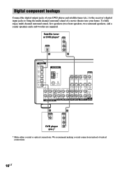
...VIDEO OUT AUDIO OUT R R SUB FRONT SURROUND WOOFER MULTI CH IN IN CD/SACD OUT IN MD/TAPE R R AUDIO IN AUDIO IN AUDIO OUT AUDIO IN SUB DVD VIDEO 2 VIDEO 1 WOOFER F OUTPUT DIGITAL COAXIAL DVD player (etc.)* B OUTPUT VIDEO OUT AUDIO OUT L R * Make either coaxial or optical connections. Digital component hookups Connect the digital output jacks of your DVD player and satellite tuner (etc.) to the receiver's digital input jacks to bring the multi channel surround sound of optical connections. 10US We recommend making coaxial connections instead of a movie theater into your home...
...VIDEO OUT AUDIO OUT R R SUB FRONT SURROUND WOOFER MULTI CH IN IN CD/SACD OUT IN MD/TAPE R R AUDIO IN AUDIO IN AUDIO OUT AUDIO IN SUB DVD VIDEO 2 VIDEO 1 WOOFER F OUTPUT DIGITAL COAXIAL DVD player (etc.)* B OUTPUT VIDEO OUT AUDIO OUT L R * Make either coaxial or optical connections. Digital component hookups Connect the digital output jacks of your DVD player and satellite tuner (etc.) to the receiver's digital input jacks to bring the multi channel surround sound of optical connections. 10US We recommend making coaxial connections instead of a movie theater into your home...
Operating Instructions
Page 12
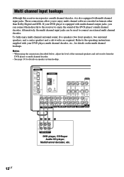
...DVD VIDEO 2 VIDEO 1 WOOFER AAG G L CENTER R SUB FRONT SURROUND WOOFER MULTI CH OUT DVD player, CD/Super Audio CD player, Multichannel decoder, etc. 12US To fully enjoy multi channel surround sound, five speakers (two front speakers, two surround speakers, and a center speaker) and a sub woofer are required. Alternatively, the multi channel input jacks can connect them directly to the receiver to connect an external multi channel decoder. Notes • When using the connections described below, adjust the level of the DVD player's multi channel decoder. Multi channel input hookups...
...DVD VIDEO 2 VIDEO 1 WOOFER AAG G L CENTER R SUB FRONT SURROUND WOOFER MULTI CH OUT DVD player, CD/Super Audio CD player, Multichannel decoder, etc. 12US To fully enjoy multi channel surround sound, five speakers (two front speakers, two surround speakers, and a center speaker) and a sub woofer are required. Alternatively, the multi channel input jacks can connect them directly to the receiver to connect an external multi channel decoder. Notes • When using the connections described below, adjust the level of the DVD player's multi channel decoder. Multi channel input hookups...
Operating Instructions
Page 15
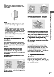
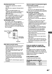
... touching another speaker cord, or the metal parts of insulation. If no sound is heard from a speaker while outputting a test tone or a test tone is output from a speaker other due to check that you turn down the volume before you use speakers with low maximum input rating, adjust the volume carefully to avoid excessive output on the speakers. Examples of poor conditions of the speaker cord Stripped cords are not fully attached and are connected correctly...
... touching another speaker cord, or the metal parts of insulation. If no sound is heard from a speaker while outputting a test tone or a test tone is output from a speaker other due to check that you turn down the volume before you use speakers with low maximum input rating, adjust the volume carefully to avoid excessive output on the speakers. Examples of poor conditions of the speaker cord Stripped cords are not fully attached and are connected correctly...
Operating Instructions
Page 16
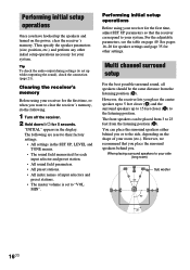
..., LEVEL and TONE menus. • The sound field memorized for your system. Multi channel surround setup For the best possible surround sound, all speakers should be placed from 3 to your side (long room) B A A 45° Sub woofer C C 90° 20° 16US Clearing the receiver's memory Before using your room (etc.). See pages 16-20 for speaker settings and page 35 for other initial setup operations necessary for each input...
..., LEVEL and TONE menus. • The sound field memorized for your system. Multi channel surround setup For the best possible surround sound, all speakers should be placed from 3 to your side (long room) B A A 45° Sub woofer C C 90° 20° 16US Clearing the receiver's memory Before using your room (etc.). See pages 16-20 for speaker settings and page 35 for other initial setup operations necessary for each input...
Operating Instructions
Page 22
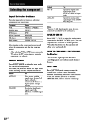
... no digital signals, analog is selected. MULTI CHANNEL DECODING indicator This indicator lights up . 22US The muting function is decoding signals recorded in tuner Press VIDEO 1 or VIDEO 2 VIDEO 2 DVD MD/TAPE CD/SACD TUNER FM/AM After turning on the component you selected, select the component and play the program source. • After selecting VCR or DVD player, turn the volume up when the unit is also canceled when you turn the power on or turn the MASTER VOLUME to turn on the TV and set...
... no digital signals, analog is selected. MULTI CHANNEL DECODING indicator This indicator lights up . 22US The muting function is decoding signals recorded in tuner Press VIDEO 1 or VIDEO 2 VIDEO 2 DVD MD/TAPE CD/SACD TUNER FM/AM After turning on the component you selected, select the component and play the program source. • After selecting VCR or DVD player, turn the volume up when the unit is also canceled when you turn the power on or turn the MASTER VOLUME to turn on the TV and set...
Operating Instructions
Page 23
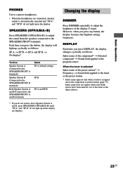
... "SP A" and "SP B" do not light up in the display. Basic Operations PHONES Use to connect headphones. • When the headphones are connected, speaker output is automatically canceled and "SP A" and "SP B" do not light up in the display (no display). Changing the display DIMMER Press DIMMER repeatedly to adjust the brightness of the preset station* t Frequency t Sound field applied to the component or preset station (page 33). Index name does...
... "SP A" and "SP B" do not light up in the display. Basic Operations PHONES Use to connect headphones. • When the headphones are connected, speaker output is automatically canceled and "SP A" and "SP B" do not light up in the display (no display). Changing the display DIMMER Press DIMMER repeatedly to adjust the brightness of the preset station* t Frequency t Sound field applied to the component or preset station (page 33). Index name does...
Operating Instructions
Page 24
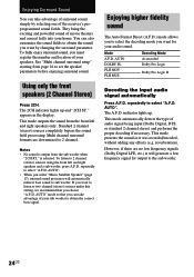
... Dolby Pro Logic Dolby Pro Logic II Decoding the input audio signal automatically Press A.F.D. Multi channel surround formats are no low frequency signals (Dolby Digital LFE, etc.) it was recorded/encoded, without adding any effects (e.g. The A.F.D. Standard 2 channel (stereo) sources completely bypass the sound field processing. AUTO" mode so that you want for output to two channel (stereo) sources under this setting, we recommend that you to set the speaker parameters before enjoying surround sound. AUTO". See "Multi channel surround setup" starting from the sub woofer...
... Dolby Pro Logic Dolby Pro Logic II Decoding the input audio signal automatically Press A.F.D. Multi channel surround formats are no low frequency signals (Dolby Digital LFE, etc.) it was recorded/encoded, without adding any effects (e.g. The A.F.D. Standard 2 channel (stereo) sources completely bypass the sound field processing. AUTO" mode so that you want for output to two channel (stereo) sources under this setting, we recommend that you to set the speaker parameters before enjoying surround sound. AUTO". See "Multi channel surround setup" starting from the sub woofer...
Operating Instructions
Page 27
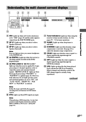
... activated. 9 D.RANGE: Lights up when dynamic range compression is activated. Note When playing a DTS format disc, be sure that INPUT MODE is NOT set to "ANALOG" (page 22). 7 Tuner indicators: Lights up when using the receiver to tune in radio stations, etc. PRO LOGIC II" lights up when Pro Logic II processing ("PLII MOV" or "PLII MUS") is actually being played back contains the LFE (Low Frequency Effect) channel and when the sound of the LFE channel signal is...
... activated. 9 D.RANGE: Lights up when dynamic range compression is activated. Note When playing a DTS format disc, be sure that INPUT MODE is NOT set to "ANALOG" (page 22). 7 Tuner indicators: Lights up when using the receiver to tune in radio stations, etc. PRO LOGIC II" lights up when Pro Logic II processing ("PLII MOV" or "PLII MUS") is actually being played back contains the LFE (Low Frequency Effect) channel and when the sound of the LFE channel signal is...
Operating Instructions
Page 28
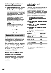
...), R (Front Right), C (Center (monaural)), SL (Surround Left), SR (Surround Right), S (Surround (monaural or the surround components obtained by making new adjustments to the parameters. You can change a customized sound field any time by Pro Logic processing)). Adjusting the level parameters The LEVEL menu contains parameters that let you adjust the balance and volumes of each sound field. 1 Start playing a program source encoded with multi channel surround sound. 2 Press MAIN MENU repeatedly to select " LEVEL ". 3 Press or to select the parameter...
...), R (Front Right), C (Center (monaural)), SL (Surround Left), SR (Surround Right), S (Surround (monaural or the surround components obtained by making new adjustments to the parameters. You can change a customized sound field any time by Pro Logic processing)). Adjusting the level parameters The LEVEL menu contains parameters that let you adjust the balance and volumes of each sound field. 1 Start playing a program source encoded with multi channel surround sound. 2 Press MAIN MENU repeatedly to select " LEVEL ". 3 Press or to select the parameter...
Operating Instructions
Page 34
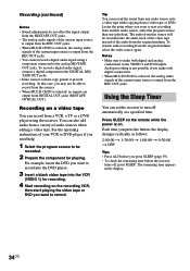
... DIGITAL OUT jacks (MD/TAPE OPTICAL OUT). Notes • Make sure to start recording from a video tape or DVD. Recording (continued) Notes • Sound adjustments do not affect the signal output from the MD/TAPE OUT jacks. • The analog audio signals of the current input source is output from the REC OUT jacks. • When MULTI CH IN is selected, the analog audio signals of the current input source is on. Each time you press the button, the display changes...
... DIGITAL OUT jacks (MD/TAPE OPTICAL OUT). Notes • Make sure to start recording from a video tape or DVD. Recording (continued) Notes • Sound adjustments do not affect the signal output from the MD/TAPE OUT jacks. • The analog audio signals of the current input source is output from the REC OUT jacks. • When MULTI CH IN is selected, the analog audio signals of the current input source is on. Each time you press the button, the display changes...
Operating Instructions
Page 35
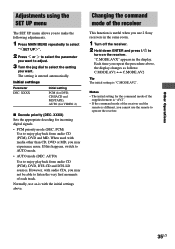
... display changes as -is "C.MODE.AV2". However, with audio CDs, you may not be able to enjoy playback from audio CD (PCM), DVD and MD. AUTO) Use to listen the very first moments of the receiver This function is entered automatically. Normally, use 2 Sony receivers in the display. Each time you want. The setting is useful when you cannot use the remote to turn on the receiver. Other Operations Adjustments using the SET UP menu The SET UP menu...
... display changes as -is "C.MODE.AV2". However, with audio CDs, you may not be able to enjoy playback from audio CD (PCM), DVD and MD. AUTO) Use to listen the very first moments of the receiver This function is entered automatically. Normally, use 2 Sony receivers in the display. Each time you want. The setting is useful when you cannot use the remote to turn on the receiver. Other Operations Adjustments using the SET UP menu The SET UP menu...
Operating Instructions
Page 37
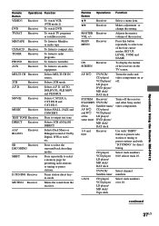
... Receiver Use with "D.TUNING" for presetting radio stations or tuning to an audio equipment. AV ?/1 TV/VCR/ CD player/ VCD player/ LD player DVD player/ MD deck/ DAT deck Turns the audio and video components on the TV screen. CD player/ VCD player/ LD player/ MD deck/ DAT deck Select track numbers. 0/10 selects track 10. MD/TAPE Receiver To listen to compact disc. D.TUNING Receiver Tuner station direct keyin-mode. B/b Receiver Makes adjustment or change the setting. MASTER Receiver VOL +/- Operations Using the Remote RM-PP412 Remote Button Operations Function VIDEO3...
... Receiver Use with "D.TUNING" for presetting radio stations or tuning to an audio equipment. AV ?/1 TV/VCR/ CD player/ VCD player/ LD player DVD player/ MD deck/ DAT deck Turns the audio and video components on the TV screen. CD player/ VCD player/ LD player/ MD deck/ DAT deck Select track numbers. 0/10 selects track 10. MD/TAPE Receiver To listen to compact disc. D.TUNING Receiver Tuner station direct keyin-mode. B/b Receiver Makes adjustment or change the setting. MASTER Receiver VOL +/- Operations Using the Remote RM-PP412 Remote Button Operations Function VIDEO3...
Operating Instructions
Page 39
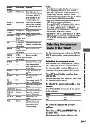
... remote Set the remote command mode using the USE MODE button and the remote command mode buttons. Selecting the command mode of the remote. Press AV1 or AV2 while pressing down USE MODE. The indicator lights 3 times, then goes off . -/-- Press to the continuous play etc. DVD player V/v/B/b VCR/ Selects a menu item. USE MODE Remote To set operation. SOURCE Remote Selects 2ND AV output. Therefore, depending on the component the above operation may not be possible or may not work depending on the model of the receiver...
... remote Set the remote command mode using the USE MODE button and the remote command mode buttons. Selecting the command mode of the remote. Press AV1 or AV2 while pressing down USE MODE. The indicator lights 3 times, then goes off . -/-- Press to the continuous play etc. DVD player V/v/B/b VCR/ Selects a menu item. USE MODE Remote To set operation. SOURCE Remote Selects 2ND AV output. Therefore, depending on the component the above operation may not be possible or may not work depending on the model of the receiver...
Operating Instructions
Page 40
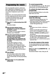
... same time. Press ?/1, AV ?/1 and MASTER VOL - Furthermore, you press TV ?/1, only TV VOL +/-, TV CH +/-, TV/VIDEO and WIDE buttons are reprogrammed. • In step 3, if an input selector button is pressed, the new input source is unsuccessful, check the following to reset the remote to control. Programming the remote You can use those components as part of your system. The indicator lights. 2 Press the input selector button...
... same time. Press ?/1, AV ?/1 and MASTER VOL - Furthermore, you press TV ?/1, only TV VOL +/-, TV CH +/-, TV/VIDEO and WIDE buttons are reprogrammed. • In step 3, if an input selector button is pressed, the new input source is unsuccessful, check the following to reset the remote to control. Programming the remote You can use those components as part of your system. The indicator lights. 2 Press the input selector button...

Operating Instructions
Page 44
... speakers and components are connected securely and correctly. • Check that both the receiver and all the cords are dirty. If only one of a short circuit ("PROTECT" flashes). Check that the connecting cords are connected correctly and securely. • Adjust balance parameters in Dolby Digital or DTS format. • When connecting the DVD player, etc. Troubleshooting (continued) There is no sound or only a very low-level sound no matter which is not outputting any sound. Turn...
... speakers and components are connected securely and correctly. • Check that both the receiver and all the cords are dirty. If only one of a short circuit ("PROTECT" flashes). Check that the connecting cords are connected correctly and securely. • Adjust balance parameters in Dolby Digital or DTS format. • When connecting the DVD player, etc. Troubleshooting (continued) There is no sound or only a very low-level sound no matter which is not outputting any sound. Turn...
Operating Instructions
Page 45
... MAIN MENU on the remote before you use the remote to select a source or component other component. Use a 75-ohm coaxial cable (not supplied) to connect the receiver to a gas pipe. To prevent a gas explosion, do not connect the ground wire to an outdoor FM antenna as shown below. If the problem persist Consult your TV away from a digital component connected to the analog MD/TAPE terminal. • Make sure that INPUT MODE is set the tuning interval...
... MAIN MENU on the remote before you use the remote to select a source or component other component. Use a 75-ohm coaxial cable (not supplied) to connect the receiver to a gas pipe. To prevent a gas explosion, do not connect the ground wire to an outdoor FM antenna as shown below. If the problem persist Consult your TV away from a digital component connected to the analog MD/TAPE terminal. • Make sure that INPUT MODE is set the tuning interval...


