Service Manual
Page 4
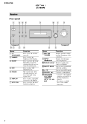
... such as MP3 player, etc.. 4 STR-K790 Receiver Front panel 1 234 ?/1 VIDEO 1 IN/ PORTABLE AUDIO IN/ AUTO CAL MIC DIMMER SLEEP 2CH A.F.D. Press to activate the Sleep Timer function and the duration which the receiver turns off . q; 9 Name H MASTER VOLUME I INPUT SELECTOR J Remote sensor K MOVIE, MUSIC L A.F.D. Receives signals from remote commander. M PHONES jack N VIDEO...
... such as MP3 player, etc.. 4 STR-K790 Receiver Front panel 1 234 ?/1 VIDEO 1 IN/ PORTABLE AUDIO IN/ AUTO CAL MIC DIMMER SLEEP 2CH A.F.D. Press to activate the Sleep Timer function and the duration which the receiver turns off . q; 9 Name H MASTER VOLUME I INPUT SELECTOR J Remote sensor K MOVIE, MUSIC L A.F.D. Receives signals from remote commander. M PHONES jack N VIDEO...
Service Manual
Page 7
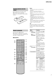
...to turn on or off the receiver and other kinds of time, remove the batteries to operate. To turn off the Sony audio/video components that the remote is assigned to avoid possible damage from battery leakage and corrosion. • When you press ?/1 (B) at the same time...Input buttons Press one of the input buttons, the receiver turns on /standby) the same time to control Sony components as follows. Remote commander You can use the remote for about 3 months. STR-K790 Inserting batteries into the remote Insert two R6 (size-AA) batteries in tuner 7 RM-AAU013 wd ws wa w;
...to turn on or off the receiver and other kinds of time, remove the batteries to operate. To turn off the Sony audio/video components that the remote is assigned to avoid possible damage from battery leakage and corrosion. • When you press ?/1 (B) at the same time...Input buttons Press one of the input buttons, the receiver turns on /standby) the same time to control Sony components as follows. Remote commander You can use the remote for about 3 months. STR-K790 Inserting batteries into the remote Insert two R6 (size-AA) batteries in tuner 7 RM-AAU013 wd ws wa w;
Service Manual
Page 9
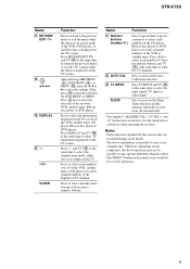
... (O) at the same time to select the input signal (TV input or video input). Press to clear a mistake when you press the incorrect numeric buttons. STR-K790 Name Q RETURN/ EXIT O R V/v/B/b S DISPLAY T -/->10/x CLEAR Function Press to return to the previous menu or exit the menu while the menu ... only. Press -/-- Notes • Some functions explained in this section may operate differently than described. • The VIDEO 3 button on the remote is intended to the previous menu or exit the TV's menu while the menu is displayed on the TV screen of the Digital CATV terminal...
... (O) at the same time to select the input signal (TV input or video input). Press to clear a mistake when you press the incorrect numeric buttons. STR-K790 Name Q RETURN/ EXIT O R V/v/B/b S DISPLAY T -/->10/x CLEAR Function Press to return to the previous menu or exit the menu while the menu ... only. Press -/-- Notes • Some functions explained in this section may operate differently than described. • The VIDEO 3 button on the remote is intended to the previous menu or exit the TV's menu while the menu is displayed on the TV screen of the Digital CATV terminal...
Service Manual
Page 15
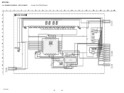
4-2. BLOCK DIAGRAM - DISPLAY/POWER SECTION - STR-K790 • R-CH is omitted due to same as L-CH. • Signal Path : FM L IC501 POWER AMP +V OUT2 12 8 IN2 NF2 9 Q501,502...Q2001,2002 DC +7V CONTROL 68 38 Q881-883 PROTECT SWITCH D841 VACS CONTROL 61 45 PROTECTOR VAX CTRL DC-CONTROL ADCC X1101 24MHz IC102 REMOTE CONTROL 1 RECEIVER 82 X0 83 X1 54 SIRCS SYSTEM CONTROL IC1101(2/2) FL_LAT FL_CLK FL_DATA 9 16 17 IC101 BUFFER IC100 FL DRIVE SEG1-17...3V REG 1 D910-913 F901 AC IN Q911 AC DET D914 D915 T900(AEP,UK) T902(US,CND) Q901 RELAY DRIVE RY901 STR-K790 15 15
4-2. BLOCK DIAGRAM - DISPLAY/POWER SECTION - STR-K790 • R-CH is omitted due to same as L-CH. • Signal Path : FM L IC501 POWER AMP +V OUT2 12 8 IN2 NF2 9 Q501,502...Q2001,2002 DC +7V CONTROL 68 38 Q881-883 PROTECT SWITCH D841 VACS CONTROL 61 45 PROTECTOR VAX CTRL DC-CONTROL ADCC X1101 24MHz IC102 REMOTE CONTROL 1 RECEIVER 82 X0 83 X1 54 SIRCS SYSTEM CONTROL IC1101(2/2) FL_LAT FL_CLK FL_DATA 9 16 17 IC101 BUFFER IC100 FL DRIVE SEG1-17...3V REG 1 D910-913 F901 AC IN Q911 AC DET D914 D915 T900(AEP,UK) T902(US,CND) Q901 RELAY DRIVE RY901 STR-K790 15 15
Service Manual
Page 32
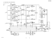
... CL105 CL106 2 C151 0.1 1 1 MASTER VOLUME INPUT SELECTOR RV101 3 2 3 C106 2200p CL107 CL108 CL109 CL110 CL111 CL112 CL113 CL114 CL115 CL116 CL117 CL11 8 CL103 JW120 5.5 IC102 REMOTE CONTROL RECEVER RPM7240-H4 IC102 1 3.3 3.3 VCC OUT GND 2 R119 10 0 3 C150 0.1 JW101 CNS102 17P 1 DC-CONTROL 2 GND 3 GND 4 +3.3V(STDBY ) 5 +5V 6 VOL_JOG_2A 7 VOL_JOG_2B...(2/4) CNP908 (Page 28) H DIGITAL BOARD (4/5) CNS513 (Page 21) CNP102 2P 1 DCAC_IN (CN2001) 2 DC-CONTROL (CN2001) L DCAC BOARD CN2001 (Page 34) No mark : FM STR-K790 32 32 SCHEMATIC DIAGRAM - STR-K790 4-19.
... CL105 CL106 2 C151 0.1 1 1 MASTER VOLUME INPUT SELECTOR RV101 3 2 3 C106 2200p CL107 CL108 CL109 CL110 CL111 CL112 CL113 CL114 CL115 CL116 CL117 CL11 8 CL103 JW120 5.5 IC102 REMOTE CONTROL RECEVER RPM7240-H4 IC102 1 3.3 3.3 VCC OUT GND 2 R119 10 0 3 C150 0.1 JW101 CNS102 17P 1 DC-CONTROL 2 GND 3 GND 4 +3.3V(STDBY ) 5 +5V 6 VOL_JOG_2A 7 VOL_JOG_2B...(2/4) CNP908 (Page 28) H DIGITAL BOARD (4/5) CNS513 (Page 21) CNP102 2P 1 DCAC_IN (CN2001) 2 DC-CONTROL (CN2001) L DCAC BOARD CN2001 (Page 34) No mark : FM STR-K790 32 32 SCHEMATIC DIAGRAM - STR-K790 4-19.
Service Manual
Page 40
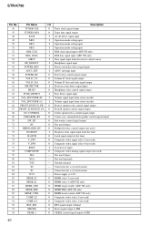
... to the tuner 75 V_SW3 O Composite video signal select 3 (not used) 76 V_SW4 O Composite video signal select 4 (not used ) 79 XIA - STR-K790 Pin No. Pin Name I/O Description 46 TUNER CLK O Tuner clock signal output 47 TUNER DATA O Tuner data signal output 48 STOP I AC off detect... signal input (AEP, UK only) 53 RDS_DATA I RDS data signal input (AEP, UK only) 54 SIRCS I Data signal input from the remote control sensor 55 HP_DETECT I Headphone signal input 56 POWER_KEY I Power switch key detect signal input 57 ADCC_INT I ADCC interrupt input 58 POWER_RY O ...
... to the tuner 75 V_SW3 O Composite video signal select 3 (not used) 76 V_SW4 O Composite video signal select 4 (not used ) 79 XIA - STR-K790 Pin No. Pin Name I/O Description 46 TUNER CLK O Tuner clock signal output 47 TUNER DATA O Tuner data signal output 48 STOP I AC off detect... signal input (AEP, UK only) 53 RDS_DATA I RDS data signal input (AEP, UK only) 54 SIRCS I Data signal input from the remote control sensor 55 HP_DETECT I Headphone signal input 56 POWER_KEY I Power switch key detect signal input 57 ADCC_INT I ADCC interrupt input 58 POWER_RY O ...


