Service Manual
Page 1
... tuning scale: 531 - 1,602 kHz Antenna Loop antenna Intermediate frequency 450 kHz 4)You can change the tuning scale. To reset the scale to 9 kHz or 10 kHz. SPECIFICATIONS AUDIO POWER SPECIFICATIONS POWER OUTPUT AND TOTAL HARMONIC DISTORTION: (Models of DTS, Inc. Amplifier section Power Output1) Stereo mode (rated) (6 ohms 1 kHz, THD 1%) 85 W + 85 W Surround mode2) (reference) (6 ohms 1 kHz, THD 10%) RMS output FRONT:133 W per channel CENTER: 133 W SURROUND: 133 W per channel minimum RMS power, with no sound output. After tuning...
... tuning scale: 531 - 1,602 kHz Antenna Loop antenna Intermediate frequency 450 kHz 4)You can change the tuning scale. To reset the scale to 9 kHz or 10 kHz. SPECIFICATIONS AUDIO POWER SPECIFICATIONS POWER OUTPUT AND TOTAL HARMONIC DISTORTION: (Models of DTS, Inc. Amplifier section Power Output1) Stereo mode (rated) (6 ohms 1 kHz, THD 1%) 85 W + 85 W Surround mode2) (reference) (6 ohms 1 kHz, THD 10%) RMS output FRONT:133 W per channel CENTER: 133 W SURROUND: 133 W per channel minimum RMS power, with no sound output. After tuning...
Service Manual
Page 2
... accurate low-voltage scale. REPLACE THESE COMPONENTS WITH SONY PARTS WHOSE PART NUMBERS APPEAR AS SHOWN IN THIS MANUAL OR IN SUPPLEMENTS PUBLISHED BY SONY. SAFETY CHECK-OUT After correcting the original service problem, perform the following characteristics. • Unleaded solder melts at a temperature about 350 °C. Leakage current can be used but unleaded solder may be set to the customer: Check the antenna...
... accurate low-voltage scale. REPLACE THESE COMPONENTS WITH SONY PARTS WHOSE PART NUMBERS APPEAR AS SHOWN IN THIS MANUAL OR IN SUPPLEMENTS PUBLISHED BY SONY. SAFETY CHECK-OUT After correcting the original service problem, perform the following characteristics. • Unleaded solder melts at a temperature about 350 °C. Leakage current can be used but unleaded solder may be set to the customer: Check the antenna...
Service Manual
Page 3
... Panel Section 42 5-2. TEST MODE 10 3. DIAGRAMS 13 4-1. Schematic Diagram - STR-K790 About area codes The area code of the receiver you purchased is shown on the lower right portion of area code AA only". Printed Wiring Board - Printed Wiring Boards - DISPLAY Board 32 4-20. ELECTRICAL PARTS LIST 44 3 Model US model Canadian model AEP, UK models Parts No. DIGITAL Board (Side A) - ...... 16 4-4. Schematic Diagram - Schematic Diagram - STANDBY Board 26 4-14. Schematic Diagram - Chassis Section 43 6. HDMI SW Board, HDMI BRIDGE...
... Panel Section 42 5-2. TEST MODE 10 3. DIAGRAMS 13 4-1. Schematic Diagram - STR-K790 About area codes The area code of the receiver you purchased is shown on the lower right portion of area code AA only". Printed Wiring Board - Printed Wiring Boards - DISPLAY Board 32 4-20. ELECTRICAL PARTS LIST 44 3 Model US model Canadian model AEP, UK models Parts No. DIGITAL Board (Side A) - ...... 16 4-4. Schematic Diagram - Schematic Diagram - STANDBY Board 26 4-14. Schematic Diagram - Chassis Section 43 6. HDMI SW Board, HDMI BRIDGE...
Service Manual
Page 4
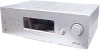
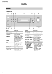
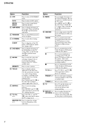
... all speakers at the same time. Press to turn the receiver on /standby) B DIMMER C SLEEP D 2CH E Display F DISPLAY G AUTO CAL Function Press to select A.F.D. To connect a portable audio such as MP3 player, etc.. 4 Connects to activate the Sleep Timer function and the duration which the receiver turns off . q; 9 Name H MASTER VOLUME I INPUT SELECTOR J Remote sensor K MOVIE, MUSIC L A.F.D. STR-K790 Receiver Front panel 1 234 ?/1 VIDEO 1 IN/ PORTABLE AUDIO IN/ AUTO CAL MIC DIMMER SLEEP 2CH A.F.D. Press to a headphone. - Turn to select the input source to...
... all speakers at the same time. Press to turn the receiver on /standby) B DIMMER C SLEEP D 2CH E Display F DISPLAY G AUTO CAL Function Press to select A.F.D. To connect a portable audio such as MP3 player, etc.. 4 Connects to activate the Sleep Timer function and the duration which the receiver turns off . q; 9 Name H MASTER VOLUME I INPUT SELECTOR J Remote sensor K MOVIE, MUSIC L A.F.D. STR-K790 Receiver Front panel 1 234 ?/1 VIDEO 1 IN/ PORTABLE AUDIO IN/ AUTO CAL MIC DIMMER SLEEP 2CH A.F.D. Press to a headphone. - Turn to select the input source to...
Service Manual
Page 5
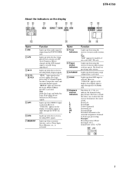
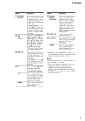
... to tune in radio stations you have preset. Name H Tuner Indicators I Preset station indicators J D.RANGE K COAX L Playback channel indicators L R C SL SR S Function Lights up when using the receiver to output the center and surround channel signals. Lights up when using the receiver to show how the receiver downmixes the source sound. The letters (L, C, R, etc.) indicate the channels being reproduced. AUTO SW LFE LCR SL SR 5 Lights up when the disc being played back contains an LFE (Low Frequency Effect) channel and the LFE channel signal is selected. "; STR-K790...
... to tune in radio stations you have preset. Name H Tuner Indicators I Preset station indicators J D.RANGE K COAX L Playback channel indicators L R C SL SR S Function Lights up when using the receiver to output the center and surround channel signals. Lights up when using the receiver to show how the receiver downmixes the source sound. The letters (L, C, R, etc.) indicate the channels being reproduced. AUTO SW LFE LCR SL SR 5 Lights up when the disc being played back contains an LFE (Low Frequency Effect) channel and the LFE channel signal is selected. "; STR-K790...
Service Manual
Page 6
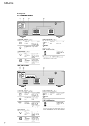
STR-K790 Rear panel US, Canadian models 12 3 4 DIGITAL OPTICAL VIDEO 2/ BD IN COAXIAL DVD IN ANTENNA AM L R AUDIO IN AUDIO IN AUDIO IN SA-CD/CD TV SAT RL SUB RL WOOFER SURROUND SPEAKERS RL RL CENTER FRONT SPEAKERS A DIGITAL INPUT section OPTICAL Connects to a CD player, etc.. The COAXIAL jack provides a better COAXIAL IN quality of loud jack sound. B ANTENNA section AUDIO IN White (L) jacks Red (R) Connects to a DVD IN jack player, etc. The COAXIAL jack provides a better COAXIAL IN quality of loud jack sound. The image and the sound are output to a...
STR-K790 Rear panel US, Canadian models 12 3 4 DIGITAL OPTICAL VIDEO 2/ BD IN COAXIAL DVD IN ANTENNA AM L R AUDIO IN AUDIO IN AUDIO IN SA-CD/CD TV SAT RL SUB RL WOOFER SURROUND SPEAKERS RL RL CENTER FRONT SPEAKERS A DIGITAL INPUT section OPTICAL Connects to a CD player, etc.. The COAXIAL jack provides a better COAXIAL IN quality of loud jack sound. B ANTENNA section AUDIO IN White (L) jacks Red (R) Connects to a DVD IN jack player, etc. The COAXIAL jack provides a better COAXIAL IN quality of loud jack sound. The image and the sound are output to a...
Service Manual
Page 7
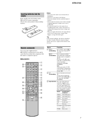
..., reassign the button again. MOVIE MUSIC AMP MENU 123 FM MODE 456 7 >10/ - m TUNING + H M TV X x 1 2 3 4 5 6 7 8 9 q; qa qs qd qf Name Function A TV ?/1 Press TV ?/1 and TV (O) at (on/standby) the same time to operate. AV ?/1 (on/standby) Press to turn on or off the Sony audio/video components that the remote is assigned to turn the receiver on /standby) Press to direct sunlight or lighting apparatuses. The buttons are factory assigned to operate. Remote commander You can use a new...
..., reassign the button again. MOVIE MUSIC AMP MENU 123 FM MODE 456 7 >10/ - m TUNING + H M TV X x 1 2 3 4 5 6 7 8 9 q; qa qs qd qf Name Function A TV ?/1 Press TV ?/1 and TV (O) at (on/standby) the same time to operate. AV ?/1 (on/standby) Press to turn on or off the Sony audio/video components that the remote is assigned to turn the receiver on /standby) Press to direct sunlight or lighting apparatuses. The buttons are factory assigned to operate. Remote commander You can use a new...
Service Manual
Page 8
... time to adjust the TV volume level. H* Press to fast forward/rewind of the VCR, CD player or Blu-ray disc player. Press TV CH +/- TUNING +/- A.F.D. m/M Press to search tracks in recording standby.) x TV CH +/- Press to select preset TV channels. and TV (O) at the same time. E AMP MENU Press to scan a station. mode. Press to display the menu of the receiver. Name Function M MENU Press to select 2CH STEREO mode. STR-K790 Name Function D 2CH Press to display...
... time to adjust the TV volume level. H* Press to fast forward/rewind of the VCR, CD player or Blu-ray disc player. Press TV CH +/- TUNING +/- A.F.D. m/M Press to search tracks in recording standby.) x TV CH +/- Press to select preset TV channels. and TV (O) at the same time. E AMP MENU Press to scan a station. mode. Press to display the menu of the receiver. Name Function M MENU Press to select 2CH STEREO mode. STR-K790 Name Function D 2CH Press to display...
Service Manual
Page 9
... references when operating the receiver. Notes • Some functions explained in this section may operate differently than described. • The VIDEO 3 button on the TV screen. STR-K790 Name Q RETURN/ EXIT O R V/v/B/b S DISPLAY T -/->10/x CLEAR Function Press to return to the previous menu or exit the menu while the menu or on-screen guide of the VCR, DVD player, or satellite tuner is displayed on the remote is intended to select track number 10.
... references when operating the receiver. Notes • Some functions explained in this section may operate differently than described. • The VIDEO 3 button on the TV screen. STR-K790 Name Q RETURN/ EXIT O R V/v/B/b S DISPLAY T -/->10/x CLEAR Function Press to return to the previous menu or exit the menu while the menu or on-screen guide of the VCR, DVD player, or satellite tuner is displayed on the remote is intended to select track number 10.
Service Manual
Page 10
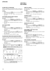
... INPUT SELECTOR dial turns on the main power. 2. STR-K790 SECTION 2 TEST MODE SOUND FIELD CLEAR MODE The preset sound field is cleared when this mode is performed. Procedure: 1. appears and initialization is activated. The model name, destination and the software version are pressed "REST 00" appears. Set the FUNCTION to turn on the main power. 2. While depressing the DIMMER and the AUTO CAL buttons simultaneously, press the power ?/1 button to turn...
... INPUT SELECTOR dial turns on the main power. 2. STR-K790 SECTION 2 TEST MODE SOUND FIELD CLEAR MODE The preset sound field is cleared when this mode is performed. Procedure: 1. appears and initialization is activated. The model name, destination and the software version are pressed "REST 00" appears. Set the FUNCTION to turn on the main power. 2. While depressing the DIMMER and the AUTO CAL buttons simultaneously, press the power ?/1 button to turn...
Service Manual
Page 11
... problem 2. DCAC board Checking Connect front left speaker, and the display will show : "DCAC[][][]x" x = 1, 2, 3 If there is error happen, below display will change accordingly. When power off : Press the three buttons MUSIC + DISPLAY + ?/1 . DCAC FACTORY TEST MODE DCAC Factory Test mode have two stages: 1. Turn MASTER VOLUME jog, there will be test tone sound output from front left speaker of test tone) STR-K790 11 Afterward, press the DIMMER to 255 (depends on loudness of the receiver and AUTO CAL microphone. DCAC DSP...
... problem 2. DCAC board Checking Connect front left speaker, and the display will show : "DCAC[][][]x" x = 1, 2, 3 If there is error happen, below display will change accordingly. When power off : Press the three buttons MUSIC + DISPLAY + ?/1 . DCAC FACTORY TEST MODE DCAC Factory Test mode have two stages: 1. Turn MASTER VOLUME jog, there will be test tone sound output from front left speaker of test tone) STR-K790 11 Afterward, press the DIMMER to 255 (depends on loudness of the receiver and AUTO CAL microphone. DCAC DSP...
Service Manual
Page 12
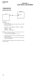
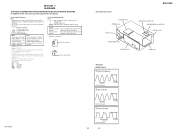
... use 75 ohm "coaxial cable" to FM tuner function and scan the input FM signal with automatic scanning. 4. Confirm that input Frequency of automatic scanning means "The station signal is 75 ohm. 3. The stop of A, B and C are detected and automatic scanning stops. Please use video cable for checking. You cannot use SG whose output impedance is received in good condition." 12 Set to connect SG and the set. STR-K790 Ver. 1.1 TUNER SECTION [FM Auto Stop Check] SET...
... use 75 ohm "coaxial cable" to FM tuner function and scan the input FM signal with automatic scanning. 4. Confirm that input Frequency of automatic scanning means "The station signal is 75 ohm. 3. The stop of A, B and C are detected and automatic scanning stops. Please use video cable for checking. You cannot use SG whose output impedance is received in good condition." 12 Set to connect SG and the set. STR-K790 Ver. 1.1 TUNER SECTION [FM Auto Stop Check] SET...
Service Manual
Page 13
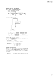
... sont critiques pour la sécurité. der no-signal (detuned) conditions. F : FM J : ANALOG c : DIGITAL I : VIDEO For Printed Wiring Boards. Note: The components identified by mark 0 or dotted line with mark 0 are dc with a VOM (Input impedance 10 MΩ). Line. • Voltages and waveforms are...mark : FM • Voltages are omitted. • Circuit Boards Location STANDBY board POWER board DCAC board HEADPHONE board DISPLAY board STR-K790 HDMI SW board (AEP,UK) HDMI BRIDGE board (AEP,UK) DIGITAL board MAIN board • Waveforms - BE BCE These are taken with respect...
... sont critiques pour la sécurité. der no-signal (detuned) conditions. F : FM J : ANALOG c : DIGITAL I : VIDEO For Printed Wiring Boards. Note: The components identified by mark 0 or dotted line with mark 0 are dc with a VOM (Input impedance 10 MΩ). Line. • Voltages and waveforms are...mark : FM • Voltages are omitted. • Circuit Boards Location STANDBY board POWER board DCAC board HEADPHONE board DISPLAY board STR-K790 HDMI SW board (AEP,UK) HDMI BRIDGE board (AEP,UK) DIGITAL board MAIN board • Waveforms - BE BCE These are taken with respect...
Service Manual
Page 15
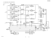
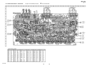
... R-CH SR-CH SR-CH R-CH Q507 AF POWER PROTECT Q607 AF POWER PROTECT SR-CH Q707 AF POWER PROTECT Q608 RELAY DRIVE RY551 R-CH TM602(1/2) L R FRONT RY601 R-CH TM604(1/2) L R SURROUND Q708 RELAY DRIVE RY701 SPEAKERS IMPEDANCE USE 6-16Ω TM602(2/2) CENTER TM604(2/2) SUB WOOFER IC850 2 PROTECT DET 7 POWER AMP -B +B -B FL101 -20V TUNER +10V RELAY +B AUDIO +7V AUDIO +5V AUDIO -7V Q851,852 -B SWITCH D811 Q801 -20V REG IC1902 3 +10V REG...
... R-CH SR-CH SR-CH R-CH Q507 AF POWER PROTECT Q607 AF POWER PROTECT SR-CH Q707 AF POWER PROTECT Q608 RELAY DRIVE RY551 R-CH TM602(1/2) L R FRONT RY601 R-CH TM604(1/2) L R SURROUND Q708 RELAY DRIVE RY701 SPEAKERS IMPEDANCE USE 6-16Ω TM602(2/2) CENTER TM604(2/2) SUB WOOFER IC850 2 PROTECT DET 7 POWER AMP -B +B -B FL101 -20V TUNER +10V RELAY +B AUDIO +7V AUDIO +5V AUDIO -7V Q851,852 -B SWITCH D811 Q801 -20V REG IC1902 3 +10V REG...
Service Manual
Page 17
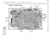
... B-7 IC1351 C-2 IC1901 B-7 IC1902 B-5 IC1904 B-6 STR-K790 DIGITAL BOARD (SIDE B) STANDBY BOARD C CNP801 (Page 26) AM TUNER FM 75 COAXIAL AEP,UK HDMI BRIDGE A BOARD CNS199 (Page 23) HS1903 HS1901 ... C1457 JL014 C1455 C1403 JL008 OPTICAL VIDEO 2/ BD IN DIGITAL COAXIAL DVD IN DIGITAL 15 BOARD (SIDE A) (Page...DIGITAL BOARD (SIDE B) - • See page 13 for FLASH PROGRAMMING • Semiconductor Location Ref. 4-4. STR-K790 8 7 6 5 4 3 2 1 MAIN D BOARD CNP504 (Page 25) DISPLAY H BOARD CNS102 (Page 31) for Circuit Boards Location. :Uses unleaded solder. PRINTED WIRING...
... B-7 IC1351 C-2 IC1901 B-7 IC1902 B-5 IC1904 B-6 STR-K790 DIGITAL BOARD (SIDE B) STANDBY BOARD C CNP801 (Page 26) AM TUNER FM 75 COAXIAL AEP,UK HDMI BRIDGE A BOARD CNS199 (Page 23) HS1903 HS1901 ... C1457 JL014 C1455 C1403 JL008 OPTICAL VIDEO 2/ BD IN DIGITAL COAXIAL DVD IN DIGITAL 15 BOARD (SIDE A) (Page...DIGITAL BOARD (SIDE B) - • See page 13 for FLASH PROGRAMMING • Semiconductor Location Ref. 4-4. STR-K790 8 7 6 5 4 3 2 1 MAIN D BOARD CNP504 (Page 25) DISPLAY H BOARD CNS102 (Page 31) for Circuit Boards Location. :Uses unleaded solder. PRINTED WIRING...
Service Manual
Page 25
... solder. STR-K790 Ver. 1.1 1 A B C DCAC E BOARD CN2001 (4pin-6pin) (Page 33) D DIGITAL F BOARD CNS501 (Page 17) E DIGITAL G F BOARD CNS502 (Page 17) G H 2 3 4 5 6 7 8 9 10 11 12 13 14 15 SA-CD/CD AUDIO IN J400 TV AUDIO IN SAT AUDIO IN MAIN BOARD AEP,UK JW853 CC54 C452 C402 R454 TP1 DCAC BOARD B CN2001 (7pin-9pin) (Page 33) SPEAKERS IMPEDANCE USE 6-16 SUB WOOFER SURROUND...
... solder. STR-K790 Ver. 1.1 1 A B C DCAC E BOARD CN2001 (4pin-6pin) (Page 33) D DIGITAL F BOARD CNS501 (Page 17) E DIGITAL G F BOARD CNS502 (Page 17) G H 2 3 4 5 6 7 8 9 10 11 12 13 14 15 SA-CD/CD AUDIO IN J400 TV AUDIO IN SAT AUDIO IN MAIN BOARD AEP,UK JW853 CC54 C452 C402 R454 TP1 DCAC BOARD B CN2001 (7pin-9pin) (Page 33) SPEAKERS IMPEDANCE USE 6-16 SUB WOOFER SURROUND...

Service Manual
Page 29
... 100p JW754 JW752 Q851,Q852 -B SWITCH R816 1 6.3 Q852 DTA124ESA-TP 6.3 D851 ISS133T-72 C816 10 100V R854 33k -5.5 R853 10k C851 0.1 R855 220k -5.5 -3.6 -5.5 7 JW607 PROTECT DET Q851 2SC1815 GR-TPE2 -37...POWER PROTECT D729 1SS133T-72 R740 100k (Page 28) RY701 RELAY 12V R724 82 D703 1SS133T-72 0.2 Q708 2SC1740S-QRT RELAY DRIVE 0.7 R725 100 RR14 10 CC14 0.01 RR15 10 CC15 0.01 RR16 10 CC16 0.01 TM604 R479 2.2k CNP504 5P L SURROUND R SPEAKERS IMPEDANCE USE 6-16 SUB WOOFER D DIGITAL BOARD (4/5) CNP506 (Page 21) No mark:FM STR-K790 29 29 4-16. SCHEMATIC DIAGRAM...
... 100p JW754 JW752 Q851,Q852 -B SWITCH R816 1 6.3 Q852 DTA124ESA-TP 6.3 D851 ISS133T-72 C816 10 100V R854 33k -5.5 R853 10k C851 0.1 R855 220k -5.5 -3.6 -5.5 7 JW607 PROTECT DET Q851 2SC1815 GR-TPE2 -37...POWER PROTECT D729 1SS133T-72 R740 100k (Page 28) RY701 RELAY 12V R724 82 D703 1SS133T-72 0.2 Q708 2SC1740S-QRT RELAY DRIVE 0.7 R725 100 RR14 10 CC14 0.01 RR15 10 CC15 0.01 RR16 10 CC16 0.01 TM604 R479 2.2k CNP504 5P L SURROUND R SPEAKERS IMPEDANCE USE 6-16 SUB WOOFER D DIGITAL BOARD (4/5) CNP506 (Page 21) No mark:FM STR-K790 29 29 4-16. SCHEMATIC DIAGRAM...
Service Manual
Page 39
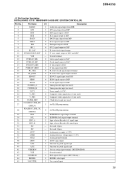
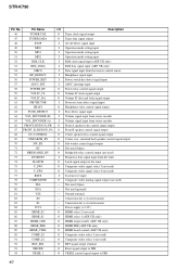
... DSP O HDIN signal output to DSP O Clock signal output to DSP I Tuning encoder input (not used ) - Not used (Open) - Ground terminal I RDS signal detect input (AEP, UK only) I MODEL select input I Analog reference voltage input (+3.3V) - Analog power supply (+3.3V) I Vacs control input STR-K790 39 Analog ground terminal I ADCC signal input I Function key push signal input I Function key push signal input I HACN signal input from DSP O Reset signal output to DSP O PM signal output to DSP O GP12 signal output to DSP O FL driver latch signal output O IC reset signal output...
... DSP O HDIN signal output to DSP O Clock signal output to DSP I Tuning encoder input (not used ) - Not used (Open) - Ground terminal I RDS signal detect input (AEP, UK only) I MODEL select input I Analog reference voltage input (+3.3V) - Analog power supply (+3.3V) I Vacs control input STR-K790 39 Analog ground terminal I ADCC signal input I Function key push signal input I Function key push signal input I HACN signal input from DSP O Reset signal output to DSP O PM signal output to DSP O GP12 signal output to DSP O FL driver latch signal output O IC reset signal output...
Service Manual
Page 40
...A speaker relay control signal output 67 FRONT_B_RY/DG51_FA O Front B speaker control signal output 68 DC-CONTROL O Center speaker relay control signal output 69 C/REAR/SB_RY O Center, rear, surround back speaker control signal output 70 SW_RY O Sub woofer control signal output 71 NC O Not used (Open) 72 BRIDGABLE_RY O Bridgeable relay control output (not used) 73 DO/SD/ST I System reset input 78 COMP MUTE O Composite video muting signal output (not used ) 77 RSTX I Frequency data signal input from the tuner 74 SLATCH O Latch signal output to DIR 40 Connection...
...A speaker relay control signal output 67 FRONT_B_RY/DG51_FA O Front B speaker control signal output 68 DC-CONTROL O Center speaker relay control signal output 69 C/REAR/SB_RY O Center, rear, surround back speaker control signal output 70 SW_RY O Sub woofer control signal output 71 NC O Not used (Open) 72 BRIDGABLE_RY O Bridgeable relay control output (not used) 73 DO/SD/ST I System reset input 78 COMP MUTE O Composite video muting signal output (not used ) 77 RSTX I Frequency data signal input from the tuner 74 SLATCH O Latch signal output to DIR 40 Connection...
Service Manual
Page 44
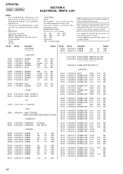
...88 IC NJM4565D < JACK > J2000 1-820-056-11 SMALL TYPE JACK (VIDEO 1 IN/PORTABLE AUDIO IN/AUTO CAL MIC) < TRANSISTOR > R2018... . The components identified by reference number, please include the board name. Replace only with ...replacements in the parts list may have some difference from the parts specified in ohms. METAL: Metal-film resistor. No. Some delay should be different from the original one. • RESISTORS All resistors are in the diagrams or the components used on the set. • -XX and -X mean standardized parts, so they are seldom required for routine service...
...88 IC NJM4565D < JACK > J2000 1-820-056-11 SMALL TYPE JACK (VIDEO 1 IN/PORTABLE AUDIO IN/AUTO CAL MIC) < TRANSISTOR > R2018... . The components identified by reference number, please include the board name. Replace only with ...replacements in the parts list may have some difference from the parts specified in ohms. METAL: Metal-film resistor. No. Some delay should be different from the original one. • RESISTORS All resistors are in the diagrams or the components used on the set. • -XX and -X mean standardized parts, so they are seldom required for routine service...


