Operating Instructions
Page 3
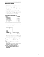
...area code CEL only". • The instructions in this manual, models of area code U is used for example, "Models of the receiver you purchased is shown on the remote. "Dolby", "Pro Logic" and the double-D symbol are trademarks of Dolby Laboratories. ** "DTS" and "DTS Digital Surround" are ...the controls on the receiver if they have the same or similar names as those on the lower right portion of the rear panel (see the illustration below). 2-XXX-XXX-XX AA Area code Any differences in operation, according to the area code, are registered trademarks of : • Receiver STR-K700 &#...
...area code CEL only". • The instructions in this manual, models of area code U is used for example, "Models of the receiver you purchased is shown on the remote. "Dolby", "Pro Logic" and the double-D symbol are trademarks of Dolby Laboratories. ** "DTS" and "DTS Digital Surround" are ...the controls on the receiver if they have the same or similar names as those on the lower right portion of the rear panel (see the illustration below). 2-XXX-XXX-XX AA Area code Any differences in operation, according to the area code, are registered trademarks of : • Receiver STR-K700 &#...
Operating Instructions
Page 9
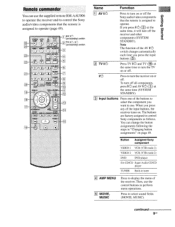
... and TV ( 16 ) at the same time, it will turn the receiver on . Press to operate. You can use the supplied remote RM-AAU006 to operate the receiver and to control the Sony audio/video components that the remote is assigned to operate (page 49). Then, use . Note The function... of the input buttons, the receiver turns on or off . Button Assigned Sony component VIDEO 1 VCR (VTR ...
... and TV ( 16 ) at the same time, it will turn the receiver on . Press to operate. You can use the supplied remote RM-AAU006 to operate the receiver and to control the Sony audio/video components that the remote is assigned to operate (page 49). Then, use . Note The function... of the input buttons, the receiver turns on or off . Button Assigned Sony component VIDEO 1 VCR (VTR ...
Operating Instructions
Page 17
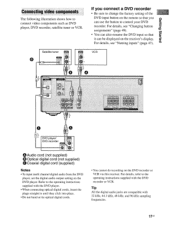
...kHz sampling frequencies. 17us papels Bu!nap Connecting video components The following illustration shows how to control your DVD recorder. Satellite tuner 86 0 If you connect a DVD recorder • Be... sure to change the factory setting of the DVD input button on the remote so that it DVD player/ DVD recorder DX UT 0*,TA GOAXIA 0 Audio cord (not supplied) 0... input multi channel digital audio from the DVD player, set the digital audio output setting on the receiver's display. VCR J. it can use the button to connect video components such as DVD player, ...
...kHz sampling frequencies. 17us papels Bu!nap Connecting video components The following illustration shows how to control your DVD recorder. Satellite tuner 86 0 If you connect a DVD recorder • Be... sure to change the factory setting of the DVD input button on the remote so that it DVD player/ DVD recorder DX UT 0*,TA GOAXIA 0 Audio cord (not supplied) 0... input multi channel digital audio from the DVD player, set the digital audio output setting on the receiver's display. VCR J. it can use the button to connect video components such as DVD player, ...
Operating Instructions
Page 47
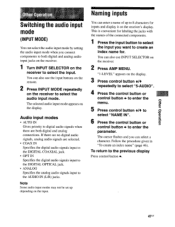
... set up to 8 characters for inputs and display it on the receiver. 2 Press AMP MENU. Audio input modes • AUTO IN Gives priority to the previous display Press control button 4.. 47 us To return to digital audio signals when there are... you want to create an index name for labeling the jacks with the names of up depending on the receiver to select the audio input mode. Naming inputs You can select the audio input mode by setting the audio...the input button to select the input you can also use the input buttons on the remote. 2 Press INPUT MODE repeatedly on the input.
... set up to 8 characters for inputs and display it on the receiver. 2 Press AMP MENU. Audio input modes • AUTO IN Gives priority to the previous display Press control button 4.. 47 us To return to digital audio signals when there are... you want to create an index name for labeling the jacks with the names of up depending on the receiver to select the audio input mode. Naming inputs You can select the audio input mode by setting the audio...the input button to select the input you can also use the input buttons on the remote. 2 Press INPUT MODE repeatedly on the input.
Operating Instructions
Page 49
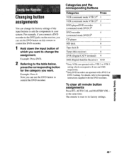
...Receiver) 0/10 °Sony VCRs are operated with a DVD 1 or DVD 3 setting. Categories and the corresponding buttons Categories Press VCR (command mode VTR 3)a) 1 VCR (command mode VTR 2)a) 2 DVD player/DVD recorder 3 (command mode DVD1)") DVD recorder 4 (command mode DVD3)b) CD player 5 MD deck 6 Tape deck B 7 Tuner (this remote to control... the DVD recorder. 1 Hold down the input button of the input buttons to control the DVD recorder. Now you can set the DVD button on the receiver, you can use the DVD button to ...
...Receiver) 0/10 °Sony VCRs are operated with a DVD 1 or DVD 3 setting. Categories and the corresponding buttons Categories Press VCR (command mode VTR 3)a) 1 VCR (command mode VTR 2)a) 2 DVD player/DVD recorder 3 (command mode DVD1)") DVD recorder 4 (command mode DVD3)b) CD player 5 MD deck 6 Tape deck B 7 Tuner (this remote to control... the DVD recorder. 1 Hold down the input button of the input buttons to control the DVD recorder. Now you can set the DVD button on the receiver, you can use the DVD button to ...
Operating Instructions
Page 54
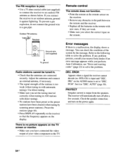
... is poor. • Use a 75-ohm coaxial cable (not supplied) to connect the receiver to an outdoor FM antenna as shown below. PRI." Set it against lightning. The receiver will automatically turn on the power again. 54US Check the speaker connection and turn off after ...the frequency appears on the receiver. • Remove any problem persists, consult your video component to solve the problem. Remote control The remote does not function. • Point the remote at the remote sensor on the display. You can check the condition of your nearest Sony dealer. Preset the stations ...
... is poor. • Use a 75-ohm coaxial cable (not supplied) to connect the receiver to an outdoor FM antenna as shown below. PRI." Set it against lightning. The receiver will automatically turn on the power again. 54US Check the speaker connection and turn off after ...the frequency appears on the receiver. • Remove any problem persists, consult your video component to solve the problem. Remote control The remote does not function. • Point the remote at the remote sensor on the display. You can check the condition of your nearest Sony dealer. Preset the stations ...
Service Manual
Page 7
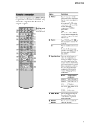
...press any of the input buttons, the receiver turns on /standby) switch 3 4 5 DUAL MONO 123 6 FM MODE 456 7 7 >10/ - wg wf wd ws wa w; To turn off all components, press ?/1 and AV ?/1 (A) at the same time, it will turn off the receiver and other components (SYSTEM STANDBY). TV .../CD Super Audio CD/CD player TUNER Built-in "Changing button assignments". If you press the input buttons (C). Press to control Sony components as follows. STR-K700 Remote commander You can change the button assignments following the steps in tuner D AMP MENU E MOVIE, MUSIC Press to display the...
...press any of the input buttons, the receiver turns on /standby) switch 3 4 5 DUAL MONO 123 6 FM MODE 456 7 7 >10/ - wg wf wd ws wa w; To turn off all components, press ?/1 and AV ?/1 (A) at the same time, it will turn off the receiver and other components (SYSTEM STANDBY). TV .../CD Super Audio CD/CD player TUNER Built-in "Changing button assignments". If you press the input buttons (C). Press to control Sony components as follows. STR-K700 Remote commander You can change the button assignments following the steps in tuner D AMP MENU E MOVIE, MUSIC Press to display the...
Service Manual
Page 13
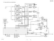
...8226; R-CH is omitted due to same as L-CH. L • Signal Path : FM A MAIN SECTION SL (Page 12) C FL101 FLUORESCENT INDICATOR TUBE SBL F1 F2 14 29 ... AMP +B Q860-862 +B SWITCH +3.3V +2.5V +5V IC1901 2 +3.3V REG 4 5 +2.5V REG IC1031 3 +5V REG 1 D804-807 T901 IC102 REMOTE 1 CONTROL RECEIVER IC850(1/2) IC850(2/2) 2 15 7 POWER AMP -B Q851,852 -B SWITCH D811 +B -B AUDIO +5V FL101 -20V Q801 -20V REG IC1001 3 +5V REG ... REG 1 R803 D920-923 F1 F2 D910-913 T902 D914 Q901 RELAY DRIVE D915 RY901 STR-K700 13 13 STR-K700 AC IN 3-2. BLOCK DIAGRAM -
...8226; R-CH is omitted due to same as L-CH. L • Signal Path : FM A MAIN SECTION SL (Page 12) C FL101 FLUORESCENT INDICATOR TUBE SBL F1 F2 14 29 ... AMP +B Q860-862 +B SWITCH +3.3V +2.5V +5V IC1901 2 +3.3V REG 4 5 +2.5V REG IC1031 3 +5V REG 1 D804-807 T901 IC102 REMOTE 1 CONTROL RECEIVER IC850(1/2) IC850(2/2) 2 15 7 POWER AMP -B Q851,852 -B SWITCH D811 +B -B AUDIO +5V FL101 -20V Q801 -20V REG IC1001 3 +5V REG ... REG 1 R803 D920-923 F1 F2 D910-913 T902 D914 Q901 RELAY DRIVE D915 RY901 STR-K700 13 13 STR-K700 AC IN 3-2. BLOCK DIAGRAM -
Service Manual
Page 32
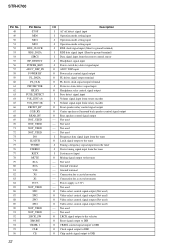
... Video select control signal output (Not used) O Video select control signal output (Not used) O Video select control signal output (Not used) O Video select control signal output (Not used - STR-K700 Pin No. ... (A) VOL_ENC (B) FRONT_RY C/SB_RY REAR_RY NOT_USED NOT_USED NOT_USED NOT_USED DO SLATCH TUNED STEREO RSTX MUTE X1A X0A VSS X0 X1 VCC3 NOT_USED SW1 SW2 SW3 SW4 NOT_USED...terminal) I Data signal input from the remote control sensor I Headphone signal input I Power switch key detect signal input O ADCC DSP input O Power relay control signal output O FL driver signal output ...
... Video select control signal output (Not used) O Video select control signal output (Not used) O Video select control signal output (Not used) O Video select control signal output (Not used - STR-K700 Pin No. ... (A) VOL_ENC (B) FRONT_RY C/SB_RY REAR_RY NOT_USED NOT_USED NOT_USED NOT_USED DO SLATCH TUNED STEREO RSTX MUTE X1A X0A VSS X0 X1 VCC3 NOT_USED SW1 SW2 SW3 SW4 NOT_USED...terminal) I Data signal input from the remote control sensor I Headphone signal input I Power switch key detect signal input O ADCC DSP input O Power relay control signal output O FL driver signal output ...


