Operating Instructions
Page 3
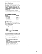
... for example, "Models of area code AA only". You can also use the controls on the receiver if they have the same or similar names as those on the supplied remote. Sub woofer SS-WP700 About area codes The area code of area code CEL only". •... The instructions in this manual describe the controls on the remote. "Dolby", "Pro Logic" and the double-D symbol are trademarks of Dolby Laboratories. ** "DTS" and "DTS Digital Surround" are registered trademarks of : • Receiver STR-K700 • Speaker system - About This Manual • The instructions in this...
... for example, "Models of area code AA only". You can also use the controls on the receiver if they have the same or similar names as those on the supplied remote. Sub woofer SS-WP700 About area codes The area code of area code CEL only". •... The instructions in this manual describe the controls on the remote. "Dolby", "Pro Logic" and the double-D symbol are trademarks of Dolby Laboratories. ** "DTS" and "DTS Digital Surround" are registered trademarks of : • Receiver STR-K700 • Speaker system - About This Manual • The instructions in this...
Operating Instructions
Page 4
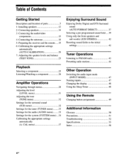
...programmed sound field 39 Using only the front speakers and sub woofer (2CH STEREO) 42 Resetting sound fields to the initial settings 42 Tuner Operations Listening to FM/AM radio 43 Presetting radio stations 44 Other Operation Switching the audio input ... 1: Installing speakers 12 2: Connecting speakers 14 3: Connecting the audio/video components 15 4: Connecting the antennas 18 5: Preparing the receiver and the remote 19 6: Calibrating the appropriate settings automatically (AUTO CALIBRATION) 20 7: Adjusting the speaker levels and balance (TEST TONE) 23 Playback...
...programmed sound field 39 Using only the front speakers and sub woofer (2CH STEREO) 42 Resetting sound fields to the initial settings 42 Tuner Operations Listening to FM/AM radio 43 Presetting radio stations 44 Other Operation Switching the audio input ... 1: Installing speakers 12 2: Connecting speakers 14 3: Connecting the audio/video components 15 4: Connecting the antennas 18 5: Preparing the receiver and the remote 19 6: Calibrating the appropriate settings automatically (AUTO CALIBRATION) 20 7: Adjusting the speaker levels and balance (TEST TONE) 23 Playback...
Operating Instructions
Page 5
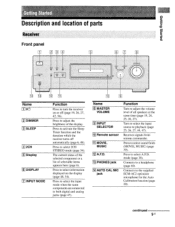
... the Sleep Timer function and the duration which the receiver turns off (page 19, 26, 27, 42...the input source to a headphone (page 40). mode (page 38). Receives signals from remote commander. Press to the supplied ECM-AC2 optimizer microphone for the Auto... Calibration function (page 20). Connects to select A.F.D. Press to adjust the brightness of parts Receiver Front... Press to turn the receiver on the display (page 48, 54). Name 181 MASTER VOLUME 191 INPUT SELECTOR 10 Remote sensor MOVIE, MUSIC 12...
... the Sleep Timer function and the duration which the receiver turns off (page 19, 26, 27, 42...the input source to a headphone (page 40). mode (page 38). Receives signals from remote commander. Press to the supplied ECM-AC2 optimizer microphone for the Auto... Calibration function (page 20). Connects to select A.F.D. Press to adjust the brightness of parts Receiver Front... Press to turn the receiver on the display (page 48, 54). Name 181 MASTER VOLUME 191 INPUT SELECTOR 10 Remote sensor MOVIE, MUSIC 12...
Operating Instructions
Page 9
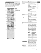
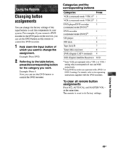
GERM: A TV CH+ AN-CIF PRFSFT J. 141 0:111j4 CU TUNING- Then, use the supplied remote RM-AAU006 to operate the receiver and to control the Sony audio/video components that the remote is assigned to operate. If you press W.) (121) at the same time, it will turn off all ... use the control buttons to use. papeis BumeD Remote commander You can change the button assignments following the steps in tuner 4 AMP MENU 5 MOVIE, MUSIC Press to select the component you press any of the receiver. Press to control Sony components as follows. TVSNLEIDEEPO ACUATLO V TV tic...
GERM: A TV CH+ AN-CIF PRFSFT J. 141 0:111j4 CU TUNING- Then, use the supplied remote RM-AAU006 to operate the receiver and to control the Sony audio/video components that the remote is assigned to operate. If you press W.) (121) at the same time, it will turn off all ... use the control buttons to use. papeis BumeD Remote commander You can change the button assignments following the steps in tuner 4 AMP MENU 5 MOVIE, MUSIC Press to select the component you press any of the receiver. Press to control Sony components as follows. TVSNLEIDEEPO ACUATLO V TV tic...
Operating Instructions
Page 17
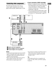
... the plugs straight in until they click into place. • Do not bend or tie optical digital cords. • You cannot do recording on the receiver's display. it DVD player/ DVD recorder DX UT 0*,TA GOAXIA 0 Audio cord (not supplied) 0 Optical digital cord (not supplied) 0 Coaxial digital cord (supplied)...; To input multi channel digital audio from the DVD player, set the digital audio output setting on the remote so that it can be displayed on the DVD recorder or VCR via this receiver. For details, see "Changing button assignments" (page 49). • You can use the button to ...
... the plugs straight in until they click into place. • Do not bend or tie optical digital cords. • You cannot do recording on the receiver's display. it DVD player/ DVD recorder DX UT 0*,TA GOAXIA 0 Audio cord (not supplied) 0 Optical digital cord (not supplied) 0 Coaxial digital cord (supplied)...; To input multi channel digital audio from the DVD player, set the digital audio output setting on the remote so that it can be displayed on the DVD recorder or VCR via this receiver. For details, see "Changing button assignments" (page 49). • You can use the button to ...
Operating Instructions
Page 19
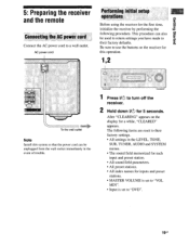
papeis Bugle° 5: Preparing the receiver and the remote Connecting the AC power cord Connect the AC power cord to their factory defaults. Be sure to use the buttons on the display for 5 seconds. After "CLEARING" appears on the receiver for this operation. 1,2 U FRONT To the wall outlet Note ...preset station. • All sound field parameters. • All preset stations. • All index names for the first time, initialize the receiver by performing the following items are reset to a wall outlet. This procedure can be used to return settings you have made to their factory ...
papeis Bugle° 5: Preparing the receiver and the remote Connecting the AC power cord Connect the AC power cord to their factory defaults. Be sure to use the buttons on the display for 5 seconds. After "CLEARING" appears on the receiver for this operation. 1,2 U FRONT To the wall outlet Note ...preset station. • All sound field parameters. • All preset stations. • All index names for the first time, initialize the receiver by performing the following items are reset to a wall outlet. This procedure can be used to return settings you have made to their factory ...

Operating Instructions
Page 20
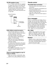
...humid place. • Do not use the remote for about 3 months. Observe the correct polarity when installing batteries. 0 0 0 Notes • Do not leave the remote in the RM-AAU006 remote commander. When the remote no longer operates the receiver, replace all the batteries with new ones. ...6: Calibrating the appropriate settings automatically (AUTO CALIBRATION) This receiver is equipped with old ones. • Do not mix...
...humid place. • Do not use the remote for about 3 months. Observe the correct polarity when installing batteries. 0 0 0 Notes • Do not leave the remote in the RM-AAU006 remote commander. When the remote no longer operates the receiver, replace all the batteries with new ones. ...6: Calibrating the appropriate settings automatically (AUTO CALIBRATION) This receiver is equipped with old ones. • Do not mix...
Operating Instructions
Page 47
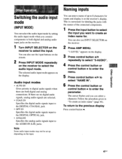
... the connected components. 1 Press the input button to select the input you want to create an index name for inputs and display it on the receiver's display. To return to the AUDIO IN (L/R) jacks. Note Some audio input modes may not be set up to 8 characters for . "1-LEVEL" ...analog audio signals are both digital and analog audio input jacks on the receiver. 1 Turn INPUT SELECTOR on the receiver to enter the parameter. You can also use the input buttons on the remote. 2 Press INPUT MODE repeatedly on the receiver to select the input. The cursor flashes and you can also use...
... the connected components. 1 Press the input button to select the input you want to create an index name for inputs and display it on the receiver's display. To return to the AUDIO IN (L/R) jacks. Note Some audio input modes may not be set up to 8 characters for . "1-LEVEL" ...analog audio signals are both digital and analog audio input jacks on the receiver. 1 Turn INPUT SELECTOR on the receiver to enter the parameter. You can also use the input buttons on the remote. 2 Press INPUT MODE repeatedly on the receiver to select the input. The cursor flashes and you can also use...
Operating Instructions
Page 49
... assignment. Example: Press 4. Now you can set the DVD button on the receiver, you want to the DVD jacks on this receiver) 8 DVR (Digital CATV terminal) 9 DSS (Digital Satellite Receiver) 0/10 °Sony VCRs are operated with the DVD recorders. The remote is reset to suit the components in your system. For details, refer to...
... assignment. Example: Press 4. Now you can set the DVD button on the receiver, you want to the DVD jacks on this receiver) 8 DVR (Digital CATV terminal) 9 DSS (Digital Satellite Receiver) 0/10 °Sony VCRs are operated with the DVD recorders. The remote is reset to suit the components in your system. For details, refer to...
Operating Instructions
Page 54
..., ground it to "DEC. If you have been cleared (when tuning by the message. Outdoor FM antenna Receiver Ground wire (not supplied) To ground Radio stations cannot be tuned in the remote with direct tuning). • No stations have been preset or the preset stations have connected the ...video output of your nearest Sony dealer. Refer to the following table to an outdoor FM antenna as shown ...
..., ground it to "DEC. If you have been cleared (when tuning by the message. Outdoor FM antenna Receiver Ground wire (not supplied) To ground Radio stations cannot be tuned in the remote with direct tuning). • No stations have been preset or the preset stations have connected the ...video output of your nearest Sony dealer. Refer to the following table to an outdoor FM antenna as shown ...

Operating Instructions
Page 57
Supplied accessories FM wire antenna (1) AM loop antenna (1) Coaxial digital cord (1) Foot pads (speakers) (20) Foot pads (sub woofer) (4) Remote commander RM-AAU006 (1) R6 (size-AA) batteries (2) Optimizer microphone ECM-AC2 (1) Speakers • Front speakers (2) • Center speaker (1) • Surround speakers (2) • Sub woofer (1) For details on the area code of the component you are subject to change without notice. 57U5 uogetuaolu IBUOWPPV Design and specifications are using, see page 3.
Supplied accessories FM wire antenna (1) AM loop antenna (1) Coaxial digital cord (1) Foot pads (speakers) (20) Foot pads (sub woofer) (4) Remote commander RM-AAU006 (1) R6 (size-AA) batteries (2) Optimizer microphone ECM-AC2 (1) Speakers • Front speakers (2) • Center speaker (1) • Surround speakers (2) • Sub woofer (1) For details on the area code of the component you are subject to change without notice. 57U5 uogetuaolu IBUOWPPV Design and specifications are using, see page 3.
Service Manual
Page 4
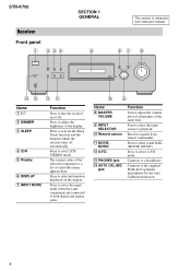
...to both digital and analog jacks. 0 9 Name H MASTER VOLUME I INPUT SELECTOR J Remote sensor K MOVIE, MUSIC L A.F.D. Press to select the input mode when the same components are connected to select 2CH STEREO mode. Receives signals from instruction manual. 67 8 qf qd qs qa Name A ?/1 B DIMMER C ..., MUSIC). Press to the supplied ECM-AC2 optimizer microphone for the Auto Calibration function. 4 STR-K700 Receiver Front panel 1 234 ?/1 SECTION 1 GENERAL 5 This section is extracted from remote commander. Press to select information displayed on or off automatically. mode.
...to both digital and analog jacks. 0 9 Name H MASTER VOLUME I INPUT SELECTOR J Remote sensor K MOVIE, MUSIC L A.F.D. Press to select the input mode when the same components are connected to select 2CH STEREO mode. Receives signals from instruction manual. 67 8 qf qd qs qa Name A ?/1 B DIMMER C ..., MUSIC). Press to the supplied ECM-AC2 optimizer microphone for the Auto Calibration function. 4 STR-K700 Receiver Front panel 1 234 ?/1 SECTION 1 GENERAL 5 This section is extracted from remote commander. Press to select information displayed on or off automatically. mode.
Service Manual
Page 7
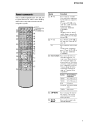
STR-K700 Remote commander You can change the button assignments following the ...or off . TUNING + m H M qg TV X x Name Function A AV ?/1 Press to turn the receiver on or off the Sony audio/video components that the remote is assigned to select the component you press ?/1 (B) at the same time (SYSTEM STANDBY). The buttons are ...MUSIC). 7 Press to use the supplied remote RM-AAU006 to operate the receiver and to control the Sony audio/video components that the remote is assigned to turn on /standby) switch 3 4 5 DUAL MONO 123 6 FM MODE 456 7 7 >10/ - qa...
STR-K700 Remote commander You can change the button assignments following the ...or off . TUNING + m H M qg TV X x Name Function A AV ?/1 Press to turn the receiver on or off the Sony audio/video components that the remote is assigned to select the component you press ?/1 (B) at the same time (SYSTEM STANDBY). The buttons are ...MUSIC). 7 Press to use the supplied remote RM-AAU006 to operate the receiver and to control the Sony audio/video components that the remote is assigned to turn on /standby) switch 3 4 5 DUAL MONO 123 6 FM MODE 456 7 7 >10/ - qa...
Service Manual
Page 13
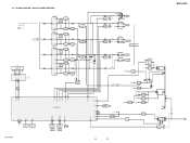
...8226; R-CH is omitted due to same as L-CH. L • Signal Path : FM A MAIN SECTION SL (Page 12) C FL101 FLUORESCENT INDICATOR TUBE SBL F1 F2 14 29 ... AMP +B Q860-862 +B SWITCH +3.3V +2.5V +5V IC1901 2 +3.3V REG 4 5 +2.5V REG IC1031 3 +5V REG 1 D804-807 T901 IC102 REMOTE 1 CONTROL RECEIVER IC850(1/2) IC850(2/2) 2 15 7 POWER AMP -B Q851,852 -B SWITCH D811 +B -B AUDIO +5V FL101 -20V Q801 -20V REG IC1001 3 +5V REG...3V REG 1 R803 D920-923 F1 F2 D910-913 T902 D914 Q901 RELAY DRIVE D915 RY901 STR-K700 13 13 STR-K700 AC IN BLOCK DIAGRAM - 3-2.
...8226; R-CH is omitted due to same as L-CH. L • Signal Path : FM A MAIN SECTION SL (Page 12) C FL101 FLUORESCENT INDICATOR TUBE SBL F1 F2 14 29 ... AMP +B Q860-862 +B SWITCH +3.3V +2.5V +5V IC1901 2 +3.3V REG 4 5 +2.5V REG IC1031 3 +5V REG 1 D804-807 T901 IC102 REMOTE 1 CONTROL RECEIVER IC850(1/2) IC850(2/2) 2 15 7 POWER AMP -B Q851,852 -B SWITCH D811 +B -B AUDIO +5V FL101 -20V Q801 -20V REG IC1001 3 +5V REG...3V REG 1 R803 D920-923 F1 F2 D910-913 T902 D914 Q901 RELAY DRIVE D915 RY901 STR-K700 13 13 STR-K700 AC IN BLOCK DIAGRAM - 3-2.
Service Manual
Page 32
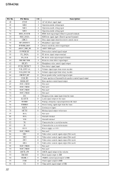
... tuner O Latch signal output to the tuner I Tuning a frequency signal input from the tuner I Stereo tuning signal input from rotary encoder O Front speaker relay control signal output O Center speaker or Surround ...signal output to DIR O Chip enable signal output to ground terminal) I Data signal input from the remote control sensor I Headphone signal input I Power switch key detect signal input O ADCC DSP input O Power... Video select control signal output (Not used) O Video select control signal output (Not used - STR-K700 Pin No. 48 49 50 51 52 53 54 55 56 57 58 59 60 61 62...
... tuner O Latch signal output to the tuner I Tuning a frequency signal input from the tuner I Stereo tuning signal input from rotary encoder O Front speaker relay control signal output O Center speaker or Surround ...signal output to DIR O Chip enable signal output to ground terminal) I Data signal input from the remote control sensor I Headphone signal input I Power switch key detect signal input O ADCC DSP input O Power... Video select control signal output (Not used) O Video select control signal output (Not used - STR-K700 Pin No. 48 49 50 51 52 53 54 55 56 57 58 59 60 61 62...


