
Operating Instructions
Page 3
... or registered trademarks of Dolby Laboratories. ** Manufactured under license under license from Dolby Laboratories. and worldwide patents issued & pending. This receiver incorporates High-Definition Multimedia Interface (HDMITM) technology. Patent #'s: 5,451,942; 5,956,674; 5,974,380; 5,978,762; 6,487...R L CENTER SPEAKERS FRONT L R Area code Any differences in operation, according to the area code, are for example, "Models of area code U only". • The instructions in this manual are clearly indicated in the text, for model STR-DG520. All Rights Reserved...
... or registered trademarks of Dolby Laboratories. ** Manufactured under license under license from Dolby Laboratories. and worldwide patents issued & pending. This receiver incorporates High-Definition Multimedia Interface (HDMITM) technology. Patent #'s: 5,451,942; 5,956,674; 5,974,380; 5,978,762; 6,487...R L CENTER SPEAKERS FRONT L R Area code Any differences in operation, according to the area code, are for example, "Models of area code U only". • The instructions in this manual are clearly indicated in the text, for model STR-DG520. All Rights Reserved...

Operating Instructions
Page 4
... audio components.........15 3b: Connecting the video components ........16 4: Connecting the antennas (aerials 24 5: Preparing the receiver and the remote .....25 6: Adjusting the speaker levels and balance (TEST TONE 26 Playback Selecting a component 28 Listening/Watching a component 29 Amplifier Operations Navigating ...MEDIA PORT (DMPORT 50 Naming inputs 52 Changing the display 53 Using the Sleep Timer 53 Recording using the receiver 54 Using the Remote Changing button assignments 54 Additional Information Glossary 55 Precautions 57 Troubleshooting 58 Specifications 61 Index 63...
... audio components.........15 3b: Connecting the video components ........16 4: Connecting the antennas (aerials 24 5: Preparing the receiver and the remote .....25 6: Adjusting the speaker levels and balance (TEST TONE 26 Playback Selecting a component 28 Listening/Watching a component 29 Amplifier Operations Navigating ...MEDIA PORT (DMPORT 50 Naming inputs 52 Changing the display 53 Using the Sleep Timer 53 Recording using the receiver 54 Using the Remote Changing button assignments 54 Additional Information Glossary 55 Precautions 57 Troubleshooting 58 Specifications 61 Index 63...

Operating Instructions
Page 5
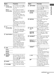
... and analog jacks (page 50). D Remote sensor Receives signals from remote commander. F INPUT MODE Press to select the input mode when the same components are connected to play back (page 28, 29, 30, 45, 46, 48, 49, 50, 52, 54). B SPEAKERS Press to turn off the sound temporarily. Press to...continued 5US MOVIE MUSIC ANALOG DIRECT MUTING qd qs Name Function A ?/1 Press to turn the speaker (ON/OFF) system on or off (page 25, 29, 30, 45, 62). MOVIE MUSIC Function Turn to turn the receiver on (on the display (page 53). Press MUTING again to high quality analog sound (page ...
... and analog jacks (page 50). D Remote sensor Receives signals from remote commander. F INPUT MODE Press to select the input mode when the same components are connected to play back (page 28, 29, 30, 45, 46, 48, 49, 50, 52, 54). B SPEAKERS Press to turn off the sound temporarily. Press to...continued 5US MOVIE MUSIC ANALOG DIRECT MUTING qd qs Name Function A ?/1 Press to turn the speaker (ON/OFF) system on or off (page 25, 29, 30, 45, 62). MOVIE MUSIC Function Turn to turn the receiver on (on the display (page 53). Press MUTING again to high quality analog sound (page ...

Operating Instructions
Page 7
... the OPTICAL jack. Lights up when using the receiver to tune in order to "NO" (page 33...be sure that you select a sound field using the receiver to tune in radio stations you have made digital connections...Preset station indicators J D.RANGE Function Lights up when the receiver is decoding DTS signals. Lights up when BD input is...Name A SW B LFE C ;D D ; Lights up when the receiver applies Pro Logic processing to "AUTO" and the source signal is a .... However, these indicators do not light up when the receiver is activated. "; Lights up when a memory function, ...
... the OPTICAL jack. Lights up when using the receiver to tune in order to "NO" (page 33...be sure that you select a sound field using the receiver to tune in radio stations you have made digital connections...Preset station indicators J D.RANGE Function Lights up when the receiver is decoding DTS signals. Lights up when BD input is...Name A SW B LFE C ;D D ; Lights up when the receiver applies Pro Logic processing to "AUTO" and the source signal is a .... However, these indicators do not light up when the receiver is activated. "; Lights up when a memory function, ...

Operating Instructions
Page 8
... or the surround components obtained by Pro Logic processing) Example: Recording format (Front/ Surround): 3/2.1 Output channel: When surround speakers are set to show how the receiver downmixes the source sound (based on the display if no digital signal is selected. The letters (L, C, R, etc.) indicate...NO" (page 33) Sound Field: A.F.D. Name K COAX L HDMI M Playback channel indicators L R C SL SR S Function Lights up when the receiver recognizes a component connected via a HDMI IN jack (page 17). However, "UNLOCK" appears on the speaker settings). AUTO SW LCR SL SR 8US
... or the surround components obtained by Pro Logic processing) Example: Recording format (Front/ Surround): 3/2.1 Output channel: When surround speakers are set to show how the receiver downmixes the source sound (based on the display if no digital signal is selected. The letters (L, C, R, etc.) indicate...NO" (page 33) Sound Field: A.F.D. Name K COAX L HDMI M Playback channel indicators L R C SL SR S Function Lights up when the receiver recognizes a component connected via a HDMI IN jack (page 17). However, "UNLOCK" appears on the speaker settings). AUTO SW LCR SL SR 8US

Operating Instructions
Page 9
.... HDMI IN/ OUT jacks* Connects to a DVD VIDEO player, TV, or a INPUT/ satellite tuner. The image and the sound are output to speakers (page 14). C SPEAKERS section Connects to a TV (page 17). D VIDEO/AUDIO INPUT/OUTPUT section AUDIO IN/ White (L) OUT jacks Red (R) VIDEO IN/ Yellow OUT jacks... L AUDIO IN IN AUDIO AUDIO OUT IN AUDIO OUT PB/CB PR/CR COMPONENT VIDEO SURROUND R L R SA-CD/CD TV SAT VIDEO SUB WOOFER CENTER SPEAKERS FRONT L R 76 5 4 3 A DIGITAL INPUT/OUTPUT section OPTICAL Connects to video and audio jacks of a VCR, a DVD player, etc. (page 19-...
.... HDMI IN/ OUT jacks* Connects to a DVD VIDEO player, TV, or a INPUT/ satellite tuner. The image and the sound are output to speakers (page 14). C SPEAKERS section Connects to a TV (page 17). D VIDEO/AUDIO INPUT/OUTPUT section AUDIO IN/ White (L) OUT jacks Red (R) VIDEO IN/ Yellow OUT jacks... L AUDIO IN IN AUDIO AUDIO OUT IN AUDIO OUT PB/CB PR/CR COMPONENT VIDEO SURROUND R L R SA-CD/CD TV SAT VIDEO SUB WOOFER CENTER SPEAKERS FRONT L R 76 5 4 3 A DIGITAL INPUT/OUTPUT section OPTICAL Connects to video and audio jacks of a VCR, a DVD player, etc. (page 19-...
Operating Instructions
Page 11
... tuning mode. Press to control Sony components. Then, use V, v, B, b and (P) to perform menu operations. Press MUTING and TV (M) at (on/standby) the same time to turn off the receiver and other components (SYSTEM STANDBY). Press to skip a track of the AV ?/1 switch changes automatically each time...the VCR, CD player, DVD player or Bluray disc player. (Also starts recording with components in "Changing button assignments" on or off all speakers at the same time (SYSTEM STANDBY). Getting Started Name Function A TV ?/1 Press TV ?/1 and TV (M) at the same time to activate...
... tuning mode. Press to control Sony components. Then, use V, v, B, b and (P) to perform menu operations. Press MUTING and TV (M) at (on/standby) the same time to turn off the receiver and other components (SYSTEM STANDBY). Press to skip a track of the AV ?/1 switch changes automatically each time...the VCR, CD player, DVD player or Bluray disc player. (Also starts recording with components in "Changing button assignments" on or off all speakers at the same time (SYSTEM STANDBY). Getting Started Name Function A TV ?/1 Press TV ?/1 and TV (M) at the same time to activate...

Operating Instructions
Page 13
...). Notes • Some functions explained in this section may operate differently than described. 1: Installing speakers This receiver allows you want. 13US To fully enjoy theater-like multi channel surround sound requires five speakers (two front speakers, a center speaker, and two surround speakers) and a sub woofer (5.1 channel). SLEEP Press to select track number 10. - Therefore, depending on...
...). Notes • Some functions explained in this section may operate differently than described. 1: Installing speakers This receiver allows you want. 13US To fully enjoy theater-like multi channel surround sound requires five speakers (two front speakers, a center speaker, and two surround speakers) and a sub woofer (5.1 channel). SLEEP Press to select track number 10. - Therefore, depending on...

Operating Instructions
Page 14
...on, it turns to standby mode automatically based on or off the function when watching movies. Note You can turn off the speaker system with an auto standby function, turn on the level of the input signal to disconnect the AC power cord (mains lead)....PR/CR COMPONENT VIDEO SURROUND R L CENTER SAT VIDEO SUB WOOFER SPEAKERS FRONT L R B 13/32 in. (10 mm) E C A Monaural audio cord (not supplied) B Speaker cords (not supplied) AFront speaker (left) BFront speaker (right) CCenter speaker DSurround speaker (left) ESurround speaker (right) FSub woofer* 14US B * When you connect a ...
...on, it turns to standby mode automatically based on or off the function when watching movies. Note You can turn off the speaker system with an auto standby function, turn on the level of the input signal to disconnect the AC power cord (mains lead)....PR/CR COMPONENT VIDEO SURROUND R L CENTER SAT VIDEO SUB WOOFER SPEAKERS FRONT L R B 13/32 in. (10 mm) E C A Monaural audio cord (not supplied) B Speaker cords (not supplied) AFront speaker (left) BFront speaker (right) CCenter speaker DSurround speaker (left) ESurround speaker (right) FSub woofer* 14US B * When you connect a ...
Operating Instructions
Page 15
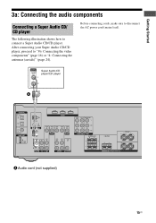
... L AUDIO IN IN AUDIO AUDIO OUT IN AUDIO OUT PB/CB PR/CR COMPONENT VIDEO SURROUND R L R SA-CD/CD TV SAT VIDEO SUB WOOFER CENTER SPEAKERS FRONT L R A Audio cord (not supplied) 15US Getting Started 3a: Connecting the audio components Connecting a Super Audio CD/ CD player The following illustration shows how to...
... L AUDIO IN IN AUDIO AUDIO OUT IN AUDIO OUT PB/CB PR/CR COMPONENT VIDEO SURROUND R L R SA-CD/CD TV SAT VIDEO SUB WOOFER CENTER SPEAKERS FRONT L R A Audio cord (not supplied) 15US Getting Started 3a: Connecting the audio components Connecting a Super Audio CD/ CD player The following illustration shows how to...

Operating Instructions
Page 17
... OUT PB/CB PR/CR COMPONENT VIDEO SURROUND R L R SA-CD/CD TV SAT VIDEO SUB WOOFER CENTER SPEAKERS FRONT L R A Coaxial digital cord (not supplied) B HDMI cable (not supplied) We recommend that you use a Sony HDMI cable. It is the abbreviated name for HighDefinition Multimedia Interface. DVD player Audio signals Audio/video signals...
... OUT PB/CB PR/CR COMPONENT VIDEO SURROUND R L R SA-CD/CD TV SAT VIDEO SUB WOOFER CENTER SPEAKERS FRONT L R A Coaxial digital cord (not supplied) B HDMI cable (not supplied) We recommend that you use a Sony HDMI cable. It is the abbreviated name for HighDefinition Multimedia Interface. DVD player Audio signals Audio/video signals...

Operating Instructions
Page 18
... area audio signals of a playback component are not output. • Video signals input to the HDMI IN jack can only be output from the speakers and to a TV via the receiver. To output the sound from the HDMI OUT jack. The input video signals cannot be output from the TV... speaker only when a playback component and this receiver, as well as this receiver and the TV are compatible with certain types of components. • Refer to the operating instructions of the multi channel surround ...
... area audio signals of a playback component are not output. • Video signals input to the HDMI IN jack can only be output from the speakers and to a TV via the receiver. To output the sound from the HDMI OUT jack. The input video signals cannot be output from the TV... speaker only when a playback component and this receiver, as well as this receiver and the TV are compatible with certain types of components. • Refer to the operating instructions of the multi channel surround ...
Operating Instructions
Page 19
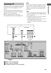
...video nor audio signals will be sure to: - It is turned on a TV screen. Connect audio and video cords according to the jacks of the receiver. - Note Be sure to turn off TV's volume or activate the TV's muting function. Audio signals TV Video signals A B C DIGITAL OPTICAL BD... L AUDIO IN IN AUDIO AUDIO OUT IN AUDIO OUT PB/CB PR/CR COMPONENT VIDEO SURROUND R L R SA-CD/CD TV SAT VIDEO SUB WOOFER CENTER SPEAKERS FRONT L R A Audio cord (not supplied) B Video cord (not supplied) C Component video cord (not supplied) 19US Before connecting cords, make sure to ...
...video nor audio signals will be sure to: - It is turned on a TV screen. Connect audio and video cords according to the jacks of the receiver. - Note Be sure to turn off TV's volume or activate the TV's muting function. Audio signals TV Video signals A B C DIGITAL OPTICAL BD... L AUDIO IN IN AUDIO AUDIO OUT IN AUDIO OUT PB/CB PR/CR COMPONENT VIDEO SURROUND R L R SA-CD/CD TV SAT VIDEO SUB WOOFER CENTER SPEAKERS FRONT L R A Audio cord (not supplied) B Video cord (not supplied) C Component video cord (not supplied) 19US Before connecting cords, make sure to ...

Operating Instructions
Page 20
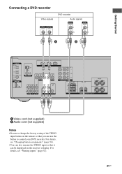
...L AUDIO IN IN AUDIO AUDIO OUT IN AUDIO OUT PB/CB PR/CR COMPONENT VIDEO SURROUND R L R SA-CD/CD TV SAT VIDEO SUB WOOFER CENTER SPEAKERS FRONT L R A Coaxial digital cord (not supplied) B Video cord (not supplied) C Component video cord (not supplied) 20US Before connecting cords, make ...not necessary to connect a DVD player/DVD recorder. To output sound from the DVD player, set the digital audio output setting on the receiver. Connecting a DVD player/DVD recorder The following illustration shows how to connect all the cords. Connect audio and video cords according to the...
...L AUDIO IN IN AUDIO AUDIO OUT IN AUDIO OUT PB/CB PR/CR COMPONENT VIDEO SURROUND R L R SA-CD/CD TV SAT VIDEO SUB WOOFER CENTER SPEAKERS FRONT L R A Coaxial digital cord (not supplied) B Video cord (not supplied) C Component video cord (not supplied) 20US Before connecting cords, make ...not necessary to connect a DVD player/DVD recorder. To output sound from the DVD player, set the digital audio output setting on the receiver. Connecting a DVD player/DVD recorder The following illustration shows how to connect all the cords. Connect audio and video cords according to the...
Operating Instructions
Page 21
... L AUDIO IN IN AUDIO AUDIO OUT IN AUDIO OUT PB/CB PR/CR COMPONENT VIDEO SURROUND R L R SA-CD/CD TV SAT VIDEO SUB WOOFER CENTER SPEAKERS FRONT L R A Video cord (not supplied) B Audio cord (not supplied) Notes • Be sure to change the factory setting of the VIDEO input button on the...
... L AUDIO IN IN AUDIO AUDIO OUT IN AUDIO OUT PB/CB PR/CR COMPONENT VIDEO SURROUND R L R SA-CD/CD TV SAT VIDEO SUB WOOFER CENTER SPEAKERS FRONT L R A Video cord (not supplied) B Audio cord (not supplied) Notes • Be sure to change the factory setting of the VIDEO input button on the...
Operating Instructions
Page 22
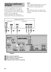
... L AUDIO IN IN AUDIO AUDIO OUT IN AUDIO OUT PB/CB PR/CR COMPONENT VIDEO SURROUND R L R SA-CD/CD TV SAT VIDEO SUB WOOFER CENTER SPEAKERS FRONT L R A Audio cord (not supplied) B Optical digital cord (not supplied) C Video cord (not supplied) D Component video cord (not supplied) 22US Tip All the digital audio...
... L AUDIO IN IN AUDIO AUDIO OUT IN AUDIO OUT PB/CB PR/CR COMPONENT VIDEO SURROUND R L R SA-CD/CD TV SAT VIDEO SUB WOOFER CENTER SPEAKERS FRONT L R A Audio cord (not supplied) B Optical digital cord (not supplied) C Video cord (not supplied) D Component video cord (not supplied) 22US Tip All the digital audio...
Operating Instructions
Page 23
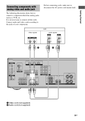
... L AUDIO IN IN AUDIO AUDIO OUT IN AUDIO OUT PB/CB PR/CR COMPONENT VIDEO SURROUND R L R SA-CD/CD TV SAT VIDEO SUB WOOFER CENTER SPEAKERS FRONT L R A Video cord (not supplied) B Audio cord (not supplied) 23US Connect audio and video cords according to connect a component which has analog jacks such as...
... L AUDIO IN IN AUDIO AUDIO OUT IN AUDIO OUT PB/CB PR/CR COMPONENT VIDEO SURROUND R L R SA-CD/CD TV SAT VIDEO SUB WOOFER CENTER SPEAKERS FRONT L R A Video cord (not supplied) B Audio cord (not supplied) 23US Connect audio and video cords according to connect a component which has analog jacks such as...
Operating Instructions
Page 24
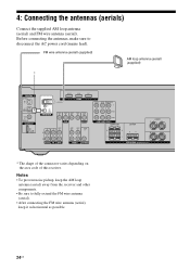
... to fully extend the FM wire antenna (aerial). • After connecting the FM wire antenna (aerial), keep the AM loop antenna (aerial) away from the receiver and other components. • Be sure to disconnect the AC power cord (mains lead). FM wire antenna (aerial) (supplied) AM loop antenna (aerial) (supplied) DIGITAL... L AUDIO IN IN AUDIO AUDIO OUT IN AUDIO OUT PB/CB PR/CR COMPONENT VIDEO SURROUND R L R SA-CD/CD TV SAT VIDEO SUB WOOFER CENTER SPEAKERS FRONT L R * The shape of the connector varies depending on the area code of this...
... to fully extend the FM wire antenna (aerial). • After connecting the FM wire antenna (aerial), keep the AM loop antenna (aerial) away from the receiver and other components. • Be sure to disconnect the AC power cord (mains lead). FM wire antenna (aerial) (supplied) AM loop antenna (aerial) (supplied) DIGITAL... L AUDIO IN IN AUDIO AUDIO OUT IN AUDIO OUT PB/CB PR/CR COMPONENT VIDEO SURROUND R L R SA-CD/CD TV SAT VIDEO SUB WOOFER CENTER SPEAKERS FRONT L R * The shape of the connector varies depending on the area code of this...

Operating Instructions
Page 25
... outlet. All the settings you have changed or adjusted are not touching each other between the speaker terminals. • Connect the AC power cord (mains lead) firmly. "PUSH" and "ENTER" appears on the receiver for this operation. 1,2 ?/1 SPEAKERS (ON/OFF) PHONES DISPLAY INPUT MODE INPUT SELECTOR MASTER VOLUME MEMORY/ TUNING ENTER MODE TUNING...
... outlet. All the settings you have changed or adjusted are not touching each other between the speaker terminals. • Connect the AC power cord (mains lead) firmly. "PUSH" and "ENTER" appears on the receiver for this operation. 1,2 ?/1 SPEAKERS (ON/OFF) PHONES DISPLAY INPUT MODE INPUT SELECTOR MASTER VOLUME MEMORY/ TUNING ENTER MODE TUNING...

Operating Instructions
Page 26
...enter the 3 Press V/v repeatedly to enter the parameter. 26US If this happens, reassign the buttons again (page 54). TV INPUT TV ?/1 SLEEP DMPORT AV ?/1 ?/1 SYSTEM STANDBY VIDEO BD DVD SAT TV SA-CD/CD TUNER Input buttons 2-5 2CH A.F.D. Notes • Do not leave the remote in the... RM-AAU020 Remote Commander. When the remote no longer operates the receiver, replace all the batteries with new ones. 6: Adjusting the speaker levels and balance (TEST TONE) You can adjust the speaker levels and balance while listening to the test tone from battery leakage and corrosion....
...enter the 3 Press V/v repeatedly to enter the parameter. 26US If this happens, reassign the buttons again (page 54). TV INPUT TV ?/1 SLEEP DMPORT AV ?/1 ?/1 SYSTEM STANDBY VIDEO BD DVD SAT TV SA-CD/CD TUNER Input buttons 2-5 2CH A.F.D. Notes • Do not leave the remote in the... RM-AAU020 Remote Commander. When the remote no longer operates the receiver, replace all the batteries with new ones. 6: Adjusting the speaker levels and balance (TEST TONE) You can adjust the speaker levels and balance while listening to the test tone from battery leakage and corrosion....


