
Limited Warranty (U.S. Only)
Page 1
... implied warranty lasts does not apply to you enter into a service contract with the Sony Partnership within the Warranty period must pay for all accessories are for all labor charges. 2. 4-557-173-02 General Stereo/Hifi Components/Tape Decks ® CD Players/Mini Disc Players/Audio Systems Hifi Audio LIMITED WARRANTY Sony Electronics Inc. ("Sony") warrants this Product is determined to be presented to obtain warranty...
... implied warranty lasts does not apply to you enter into a service contract with the Sony Partnership within the Warranty period must pay for all accessories are for all labor charges. 2. 4-557-173-02 General Stereo/Hifi Components/Tape Decks ® CD Players/Mini Disc Players/Audio Systems Hifi Audio LIMITED WARRANTY Sony Electronics Inc. ("Sony") warrants this Product is determined to be presented to obtain warranty...
Operating Instructions
Page 3
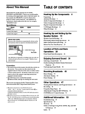
... 4 Antenna Hookups 5 Audio Component Hookups 6 Video Component Hookups 8 Digital Component Hookups 9 5.1CH Input Hookups 11 Other Hookups 12 Hooking Up and Setting Up the Speaker System 15 Speaker System Hookup 16 Performing Initial Setup Operations 18 Multi Channel Surround Setup 19 Before You Use Your Receiver 23 Location of Parts and Basic Operations 26 Front Panel Parts Description 26 Enjoying Surround Sound 31 Selecting a Sound Field 32 Understanding the Multi-Channel Surround Displays 36 Customizing Sound Fields 38 Receiving Broadcasts 43 Direct Tuning 44 Automatic Tuning 45 Preset...
... 4 Antenna Hookups 5 Audio Component Hookups 6 Video Component Hookups 8 Digital Component Hookups 9 5.1CH Input Hookups 11 Other Hookups 12 Hooking Up and Setting Up the Speaker System 15 Speaker System Hookup 16 Performing Initial Setup Operations 18 Multi Channel Surround Setup 19 Before You Use Your Receiver 23 Location of Parts and Basic Operations 26 Front Panel Parts Description 26 Enjoying Surround Sound 31 Selecting a Sound Field 32 Understanding the Multi-Channel Surround Displays 36 Customizing Sound Fields 38 Receiving Broadcasts 43 Direct Tuning 44 Automatic Tuning 45 Preset...
Operating Instructions
Page 6
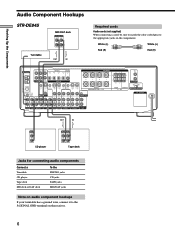
... player INPUT OUTPUT LINE LINE L R Tape deck Jacks for connecting audio components Connect a Turntable CD player Tape deck MD deck or DAT deck To the PHONO jacks CD jacks TAPE jacks MD/DAT jacks Note on audio component hookups If your turntable has a ground wire, connect it to the appropriate jacks on the receiver. 6 White (L) White (L) Red (R) Red (R) ANTENNA AM y COAXIAL FM 75Ω FRONT REAR L CENTER MD/DAT OUT OPTICAL MD/DAT IN TV/SAT IN DVD/LD IN COAX DVD/LD IN R SUB 5.1CH INPUT WOOFER DIGITAL CTRL S S-VIDEO CTRL S S-VIDEO S-VIDEO CTRL...
... player INPUT OUTPUT LINE LINE L R Tape deck Jacks for connecting audio components Connect a Turntable CD player Tape deck MD deck or DAT deck To the PHONO jacks CD jacks TAPE jacks MD/DAT jacks Note on audio component hookups If your turntable has a ground wire, connect it to the appropriate jacks on the receiver. 6 White (L) White (L) Red (R) Red (R) ANTENNA AM y COAXIAL FM 75Ω FRONT REAR L CENTER MD/DAT OUT OPTICAL MD/DAT IN TV/SAT IN DVD/LD IN COAX DVD/LD IN R SUB 5.1CH INPUT WOOFER DIGITAL CTRL S S-VIDEO CTRL S S-VIDEO S-VIDEO CTRL...
Operating Instructions
Page 8
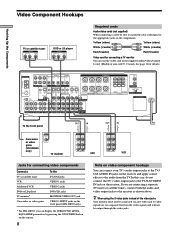
... you can display the SURROUND, LEVEL, EQUALIZER parameters by pressing the ON SCREEN button on the remote. 8 Note on video component hookups You can use the video cord of the supplied audio/video/control S cord. (Models of the video jacks Your monitor must also be output through the video jacks. Ç Ç Hooking Up the Components Video Component Hookups TV or satellite tuner OUTPUT AUDIO OUT R L VIDEO OUT DVD or LD player OUTPUT AUDIO OUT R L VIDEO OUT Required cords Audio/video cords (not supplied) When connecting a cord, be sure to match the color-coded pins...
... you can display the SURROUND, LEVEL, EQUALIZER parameters by pressing the ON SCREEN button on the remote. 8 Note on video component hookups You can use the video cord of the supplied audio/video/control S cord. (Models of the video jacks Your monitor must also be output through the video jacks. Ç Ç Hooking Up the Components Video Component Hookups TV or satellite tuner OUTPUT AUDIO OUT R L VIDEO OUT DVD or LD player OUTPUT AUDIO OUT R L VIDEO OUT Required cords Audio/video cords (not supplied) When connecting a cord, be sure to match the color-coded pins...

Operating Instructions
Page 9
... instruction manual supplied with an RF OUT jack via an RF demodulator Please note that you cannot connect an LD player's AC-3 RF OUT jack directly to this unit's OPT or COAX DVD/LD IN jack. LEVEL A B C TAPE MD/DAT CD TUNER PHONO SOUND FIELD SUR A.F.D. 2CH MODE EQ EQUALIZER BASS BOOST MASTER VOLUME PRESET - Hooking Up the Components Digital Component Hookups Connect the digital output jacks of your DVD player and satellite tuner (etc.) to the receiver's digital input jacks to bring the multi channel surround sound of a movie theater...
... instruction manual supplied with an RF OUT jack via an RF demodulator Please note that you cannot connect an LD player's AC-3 RF OUT jack directly to this unit's OPT or COAX DVD/LD IN jack. LEVEL A B C TAPE MD/DAT CD TUNER PHONO SOUND FIELD SUR A.F.D. 2CH MODE EQ EQUALIZER BASS BOOST MASTER VOLUME PRESET - Hooking Up the Components Digital Component Hookups Connect the digital output jacks of your DVD player and satellite tuner (etc.) to the receiver's digital input jacks to bring the multi channel surround sound of a movie theater...

Operating Instructions
Page 10
... IN ANTENNA AM y COAXIAL FM 75Ω FRONT REAR L CENTER MD/DAT OUT OPTICAL MD/DAT IN TV/SAT IN DVD/LD IN COAX DVD/LD IN R SUB 5.1CH INPUT WOOFER DIGITAL CTRL S S-VIDEO CTRL S S-VIDEO S-VIDEO CTRL S IN OUT STATUS IN IN IN OUT VIDEO OUT CTRL S S-VIDEO S-VIDEO OUT OUT IN B + SPEAKERS A R L ++ + R L R L - - - - These connections allow you cannot make a digital recording of a digital multi channel surround signal. • To make analog connections. ç ç Hooking Up the Components Digital Component Hookups Connect the digital output jacks...
... IN ANTENNA AM y COAXIAL FM 75Ω FRONT REAR L CENTER MD/DAT OUT OPTICAL MD/DAT IN TV/SAT IN DVD/LD IN COAX DVD/LD IN R SUB 5.1CH INPUT WOOFER DIGITAL CTRL S S-VIDEO CTRL S S-VIDEO S-VIDEO CTRL S IN OUT STATUS IN IN IN OUT VIDEO OUT CTRL S S-VIDEO S-VIDEO OUT OUT IN B + SPEAKERS A R L ++ + R L R L - - - - These connections allow you cannot make a digital recording of a digital multi channel surround signal. • To make analog connections. ç ç Hooking Up the Components Digital Component Hookups Connect the digital output jacks...
Operating Instructions
Page 11
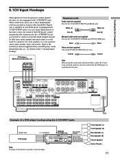
... the 5.1CH INPUT CENTER and SUB WOOFER jacks Black Black Video cord (not supplied) One for the DVD/LD VIDEO IN jacks (etc.) Yellow Yellow Note When using the 5.1CH INPUT jacks VIDEO OUT DVD player 5.1 CH INPUT DVD/LD IN VIDEO etc. Refer to the instruction manual supplied with 5.1CH OUTPUT jacks, you can be used to connect an external multi channel decoder. LEVEL A B C TAPE MD/DAT CD TUNER PHONO SOUND FIELD SUR A.F.D. 2CH MODE EQ EQUALIZER BASS BOOST MASTER VOLUME PRESET - To fully enjoy multi channel surround sound, you to...
... the 5.1CH INPUT CENTER and SUB WOOFER jacks Black Black Video cord (not supplied) One for the DVD/LD VIDEO IN jacks (etc.) Yellow Yellow Note When using the 5.1CH INPUT jacks VIDEO OUT DVD player 5.1 CH INPUT DVD/LD IN VIDEO etc. Refer to the instruction manual supplied with 5.1CH OUTPUT jacks, you can be used to connect an external multi channel decoder. LEVEL A B C TAPE MD/DAT CD TUNER PHONO SOUND FIELD SUR A.F.D. 2CH MODE EQ EQUALIZER BASS BOOST MASTER VOLUME PRESET - To fully enjoy multi channel surround sound, you to...
Operating Instructions
Page 12
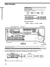
... sub room hookup using the 2ND AUDIO OUT jacks (STR-DE945 only) You can use the 2ND AUDIO OUT jacks to output audio signals to which the receiver is selected. 12 VIDEO 1 VIDEO 2 VIDEO 3 DVD/LD TV/SAT CINEMA STUDIO EX. A B C LEVEL TAPE MD/DAT CD TUNER PHONO SOUND FIELD SUR A.F.D. 2CH MODE EQ + SET UP NAME ENTER EQUALIZER BASS BOOST MASTER VOLUME 0 10 PRESET - TUNING + SHIFT - White (L) White (L) Red (R) Red (R) Audio/video/control S connecting cord (1)** Yellow (video) A White (L/audio) B Red (R/audio) C Black (control S) D Yellow (video) A White (L/audio) B Red (R/audio...
... sub room hookup using the 2ND AUDIO OUT jacks (STR-DE945 only) You can use the 2ND AUDIO OUT jacks to output audio signals to which the receiver is selected. 12 VIDEO 1 VIDEO 2 VIDEO 3 DVD/LD TV/SAT CINEMA STUDIO EX. A B C LEVEL TAPE MD/DAT CD TUNER PHONO SOUND FIELD SUR A.F.D. 2CH MODE EQ + SET UP NAME ENTER EQUALIZER BASS BOOST MASTER VOLUME 0 10 PRESET - TUNING + SHIFT - White (L) White (L) Red (R) Red (R) Audio/video/control S connecting cord (1)** Yellow (video) A White (L/audio) B Red (R/audio) C Black (control S) D Yellow (video) A White (L/audio) B Red (R/audio...
Operating Instructions
Page 18
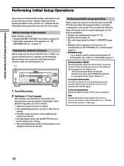
... operation (page 50). - To cancel the demonstration Press ?/1 to their factory settings. • The sound field memorized for the first time, or when you want to adjust the setup parameters so that you have hooked up the speakers and turned on or off during the previous message. VIDEO 1 VIDEO 2 VIDEO 3 DVD/LD TV/SAT CINEMA STUDIO EX. LEVEL A B C TAPE MD/DAT CD TUNER PHONO SOUND FIELD SUR A.F.D. 2CH MODE EQ EQUALIZER BASS BOOST MASTER VOLUME PRESET...
... operation (page 50). - To cancel the demonstration Press ?/1 to their factory settings. • The sound field memorized for the first time, or when you want to adjust the setup parameters so that you have hooked up the speakers and turned on or off during the previous message. VIDEO 1 VIDEO 2 VIDEO 3 DVD/LD TV/SAT CINEMA STUDIO EX. LEVEL A B C TAPE MD/DAT CD TUNER PHONO SOUND FIELD SUR A.F.D. 2CH MODE EQ EQUALIZER BASS BOOST MASTER VOLUME PRESET...
Operating Instructions
Page 22
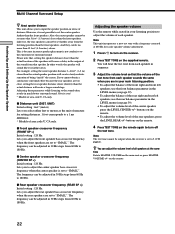
... surround sound. And they can be output when the receiver is set to adjust the volume of each speaker sounds the same when you are set to turn off the test tone. Give it is not conducive to turn on the receiver. 2 Press TEST TONE on the supplied remote. x Center speaker crossover frequency (CENTER SP >) Initial setting : 120 Hz Lets you to adjust the center speaker bass crossover frequency when the center speaker is set to a 1 ms difference. * Models of area code U, CA only. Adjusting the speaker volume Use...
... surround sound. And they can be output when the receiver is set to adjust the volume of each speaker sounds the same when you are set to turn off the test tone. Give it is not conducive to turn on the receiver. 2 Press TEST TONE on the supplied remote. x Center speaker crossover frequency (CENTER SP >) Initial setting : 120 Hz Lets you to adjust the center speaker bass crossover frequency when the center speaker is set to a 1 ms difference. * Models of area code U, CA only. Adjusting the speaker volume Use...
Operating Instructions
Page 23
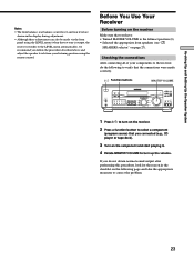
... - TUNING + MEMORY FM/AM FM MODE 2ND AUDIO + SET UP NAME ENTER 0 BASS MUTING EQUALIZER BOOST VIDEO 3 INPUT 10 VIDEO L AUDIO R 1 Press ?/1 to turn up the volume. If you connected (e.g., CD player or tape deck). 3 Turn on the component and start playing it. 4 Rotate MASTER VOLUME to turn on the receiver. 2 Press a function button to select a component (program source) that you do the following page and take the appropriate measures to correct the problem. 23 VIDEO 1 VIDEO 2 VIDEO 3 DVD/LD TV/SAT CINEMA STUDIO EX. Before You Use...
... - TUNING + MEMORY FM/AM FM MODE 2ND AUDIO + SET UP NAME ENTER 0 BASS MUTING EQUALIZER BOOST VIDEO 3 INPUT 10 VIDEO L AUDIO R 1 Press ?/1 to turn up the volume. If you connected (e.g., CD player or tape deck). 3 Turn on the component and start playing it. 4 Rotate MASTER VOLUME to turn on the receiver. 2 Press a function button to select a component (program source) that you do the following page and take the appropriate measures to correct the problem. 23 VIDEO 1 VIDEO 2 VIDEO 3 DVD/LD TV/SAT CINEMA STUDIO EX. Before You Use...

Operating Instructions
Page 26
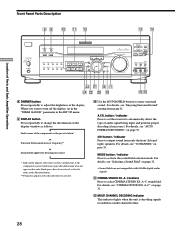
... receiver, make sure that you have turned the MASTER VOLUME control to the leftmost position to avoid damaging your speakers. 2 Function buttons Press one of the buttons to select the component you want to match the component you selected. 26 It also explains basic operations. To select Press VCR VIDEO 1 or VIDEO 2 Camcorder or video game VIDEO 3 (STR-DE945 only) DVD or LD player DVD/LD TV or satellite tuner TV/SAT Tape deck MD or Tape deck TAPE (STR-DE945) MD/TAPE (STR...
... receiver, make sure that you have turned the MASTER VOLUME control to the leftmost position to avoid damaging your speakers. 2 Function buttons Press one of the buttons to select the component you want to match the component you selected. 26 It also explains basic operations. To select Press VCR VIDEO 1 or VIDEO 2 Camcorder or video game VIDEO 3 (STR-DE945 only) DVD or LD player DVD/LD TV or satellite tuner TV/SAT Tape deck MD or Tape deck TAPE (STR-DE945) MD/TAPE (STR...

Operating Instructions
Page 27
... speaker output * Be sure to connect front speakers with a nominal impedance of 8 ohms or higher if you selected, rotate to adjust the volume. 6 MUTING button Press to select "5.1CH V:" (see page 50 for your digital components (DVD/LD, TV/SAT, and MD/DAT (STR-DE945) or MD/TAPE (STR-DE845)). LEVEL A B C TAPE MD/DAT CD TUNER PHONO SOUND FIELD SUR A.F.D. 2CH MODE EQ EQUALIZER BASS BOOST MASTER VOLUME PRESET - The indicator on the component you want to the 5.1CH INPUT jacks. Selecting other sound...
... speaker output * Be sure to connect front speakers with a nominal impedance of 8 ohms or higher if you selected, rotate to adjust the volume. 6 MUTING button Press to select "5.1CH V:" (see page 50 for your digital components (DVD/LD, TV/SAT, and MD/DAT (STR-DE945) or MD/TAPE (STR-DE845)). LEVEL A B C TAPE MD/DAT CD TUNER PHONO SOUND FIELD SUR A.F.D. 2CH MODE EQ EQUALIZER BASS BOOST MASTER VOLUME PRESET - The indicator on the component you want to the 5.1CH INPUT jacks. Selecting other sound...
Operating Instructions
Page 28
...Basic Amplifier Operations Front Panel Parts Description 8 9 0 qa qs qd qf SPEAKERS OFF A B A+B PHONES MULTI CHANNEL DECODING DIMMER DISPLAY INPUT MODE 5.1CH INPUT - A~C sound field. A.F.D. TUNING + SHIFT - button / indicator Press to output sound from page 31. For details, see "AUTO FORMAT DECODING" on the display window as the function button. ** Frequency appears only when the tuner is decoding signals recorded in the "DIMM. TUNING + MEMORY FM/AM FM MODE 2ND AUDIO + SET UP NAME ENTER 0 BASS MUTING EQUALIZER BOOST VIDEO 3 INPUT 10 VIDEO L AUDIO R wd...
...Basic Amplifier Operations Front Panel Parts Description 8 9 0 qa qs qd qf SPEAKERS OFF A B A+B PHONES MULTI CHANNEL DECODING DIMMER DISPLAY INPUT MODE 5.1CH INPUT - A~C sound field. A.F.D. TUNING + SHIFT - button / indicator Press to output sound from page 31. For details, see "AUTO FORMAT DECODING" on the display window as the function button. ** Frequency appears only when the tuner is decoding signals recorded in the "DIMM. TUNING + MEMORY FM/AM FM MODE 2ND AUDIO + SET UP NAME ENTER 0 BASS MUTING EQUALIZER BOOST VIDEO 3 INPUT 10 VIDEO L AUDIO R wd...
Operating Instructions
Page 30
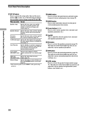
... Parts and Basic Amplifier Operations Front Panel Parts Description qj SET UP button Press to activate the setup mode, then use the cursor buttons (w;) to select any of the on-screen (STR-DE945 only) display (page 51). Crossover frequency* Specify the front, center, and rear speaker bass crossover frequency (page 22). 5.1CH video input Specify the video input to activate the equalizer parameters (page 40). ws EQ button Press to be used with the audio signals from the 2 way remote (page 50). You can Speaker setup...
... Parts and Basic Amplifier Operations Front Panel Parts Description qj SET UP button Press to activate the setup mode, then use the cursor buttons (w;) to select any of the on-screen (STR-DE945 only) display (page 51). Crossover frequency* Specify the front, center, and rear speaker bass crossover frequency (page 22). 5.1CH video input Specify the video input to activate the equalizer parameters (page 40). ws EQ button Press to be used with the audio signals from the 2 way remote (page 50). You can Speaker setup...

Operating Instructions
Page 32
... TUNER PHONO SOUND FIELD SUR A.F.D. 2CH MODE EQ EQUALIZER BASS BOOST MASTER VOLUME PRESET - button: Press to set the receiver to automatically detect the type of audio signal being input and perform proper decoding (if necessary). 2CH button: Press to activate the sound field selection mode. With the tuner, sound fields are labeled with STADIUM as the sound field, change to a different program source, then return to CD with the A logo. 32 VIDEO 1 VIDEO 2 VIDEO 3 DVD/LD TV/SAT CINEMA...
... TUNER PHONO SOUND FIELD SUR A.F.D. 2CH MODE EQ EQUALIZER BASS BOOST MASTER VOLUME PRESET - button: Press to set the receiver to automatically detect the type of audio signal being input and perform proper decoding (if necessary). 2CH button: Press to activate the sound field selection mode. With the tuner, sound fields are labeled with STADIUM as the sound field, change to a different program source, then return to CD with the A logo. 32 VIDEO 1 VIDEO 2 VIDEO 3 DVD/LD TV/SAT CINEMA...
Operating Instructions
Page 47
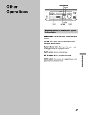
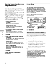
... TUNER PHONO SOUND FIELD SUR A.F.D. 2CH MODE EQ EQUALIZER BASS BOOST MASTER VOLUME PRESET - TUNER button: Press to enter the set up mode. SET UP button: Press to select the tuner. TUNING + MEMORY FM/AM FM MODE 2ND AUDIO + SET UP NAME ENTER 0 BASS MUTING EQUALIZER BOOST VIDEO 3 INPUT 10 VIDEO L AUDIO R TUNER ENTER Jog dial NAME Brief descriptions of buttons that appear in this chapter NAME button: Press to enter the completed name of the preset station or program source. ENTER button: Press to name preset stations or program sources. TUNING...
... TUNER PHONO SOUND FIELD SUR A.F.D. 2CH MODE EQ EQUALIZER BASS BOOST MASTER VOLUME PRESET - TUNER button: Press to enter the set up mode. SET UP button: Press to select the tuner. TUNING + MEMORY FM/AM FM MODE 2ND AUDIO + SET UP NAME ENTER 0 BASS MUTING EQUALIZER BOOST VIDEO 3 INPUT 10 VIDEO L AUDIO R TUNER ENTER Jog dial NAME Brief descriptions of buttons that appear in this chapter NAME button: Press to enter the completed name of the preset station or program source. ENTER button: Press to name preset stations or program sources. TUNING...
Operating Instructions
Page 48
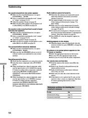
.../TAPE OUT jacks (STR-DE845). • Sound adjustments do not affect the signal output from the components connected to it easy to record to be changed flashes, then turn the jog dial to 5. Function buttons Playback component (program source) l: Audio signal flow .: Video signal flow Recording component (tape deck, MD deck, VCR) Recording on an audio tape or MiniDisc You can record and edit as "VHS" and "8mm," respectively. LEVEL A B C TAPE MD/DAT CD TUNER PHONO SOUND FIELD SUR A.F.D. 2CH MODE EQ EQUALIZER BASS BOOST MASTER VOLUME PRESET...
.../TAPE OUT jacks (STR-DE845). • Sound adjustments do not affect the signal output from the components connected to it easy to record to be changed flashes, then turn the jog dial to 5. Function buttons Playback component (program source) l: Audio signal flow .: Video signal flow Recording component (tape deck, MD deck, VCR) Recording on an audio tape or MiniDisc You can record and edit as "VHS" and "8mm," respectively. LEVEL A B C TAPE MD/DAT CD TUNER PHONO SOUND FIELD SUR A.F.D. 2CH MODE EQ EQUALIZER BASS BOOST MASTER VOLUME PRESET...
Operating Instructions
Page 54
..., use the remote to DIGITAL (see page 27) before operating the receiver or other than TV before recording with new ones, if they are weak. , Make sure you connected two sets of front speakers. MODE). , Make sure that the components are connected securely. Preset the stations (see page 45). , Press DISPLAY so that the antennas are connected correctly. , Select the source component with a FUNCTION button. , When recording from a digital component, make sure the input mode...
..., use the remote to DIGITAL (see page 27) before operating the receiver or other than TV before recording with new ones, if they are weak. , Make sure you connected two sets of front speakers. MODE). , Make sure that the components are connected securely. Preset the stations (see page 45). , Press DISPLAY so that the antennas are connected correctly. , Select the source component with a FUNCTION button. , When recording from a digital component, make sure the input mode...
Operating Instructions
Page 61
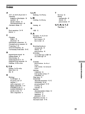
... 38~42 pre-programmed 33~35 resetting 41 selecting 32 Speakers adjusting speaker volume 22 connection 16 impedance 17 placement 19~22 Supplied accessories 4 Surround sound 31~42 T Test tone 22 Tuning automatically 45 directly 44 preset stations 45 U, V, W, X, Y, Z Unpacking 4 Additional Information 61 Index A AC-3. See Recording E, F, G Editing. See Recording Effect level 38 EQ 40 H Hookups 5.1 CH input 11 AC power cord 14 antennas 5 audio components 6, 7 digital components 9, 10 CONTROL A1 II 12 S-LINK CONTROL S 13 speaker system 16 video components 8 I, J, K Indexing. See...
... 38~42 pre-programmed 33~35 resetting 41 selecting 32 Speakers adjusting speaker volume 22 connection 16 impedance 17 placement 19~22 Supplied accessories 4 Surround sound 31~42 T Test tone 22 Tuning automatically 45 directly 44 preset stations 45 U, V, W, X, Y, Z Unpacking 4 Additional Information 61 Index A AC-3. See Recording E, F, G Editing. See Recording Effect level 38 EQ 40 H Hookups 5.1 CH input 11 AC power cord 14 antennas 5 audio components 6, 7 digital components 9, 10 CONTROL A1 II 12 S-LINK CONTROL S 13 speaker system 16 video components 8 I, J, K Indexing. See...


