
Operating Instructions
Page 3
About This Manual Note for the supplied remote For RM-U185 About area codes AC OUTLET 4-XXX-XXX-XX AA 3GB
About This Manual Note for the supplied remote For RM-U185 About area codes AC OUTLET 4-XXX-XXX-XX AA 3GB

Operating Instructions
Page 4
Table of Contents Getting Started Amplifier Operation Operations Using the Remote RM-U185 Additional Information Other Operations 4GB
Table of Contents Getting Started Amplifier Operation Operations Using the Remote RM-U185 Additional Information Other Operations 4GB

Operating Instructions
Page 12
Presetting radio stations Presetting radio stations 1 2 3 4 5 Tuning to preset stations 1 2 tA1yA2y...yA0yB1yB2y...yB0T tC0y...yC2yC1T Using the remote 1 2 To select the preset station directly 6 Note 12GB
Presetting radio stations Presetting radio stations 1 2 3 4 5 Tuning to preset stations 1 2 tA1yA2y...yA0yB1yB2y...yB0T tC0y...yC2yC1T Using the remote 1 2 To select the preset station directly 6 Note 12GB
Operating Instructions
Page 19
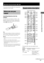
CH/PRESET + .> m M D. TUNING ENTER RETURN TV/VIDEO ANT TV/VTR D.SKIP ws wa w; 9 N X x ql q; L BALANCE R BASS BOOST qa qk - qg w; 19GB TREBLE + MUTING qs qj qd - BASS + MASTER VOL + + qh qf TV VOL TV CH - - Operations Using the Remote RM-U185 Before you use your remote Inserting batteries into the remote Tip Notes Remote button description SLEEP AV ?/1 ?/1 1 wj 2 SYSTEM STANDBY wh 3 VIDEO 1 VIDEO 2 DVD • wg 4 MD/TAPE CD TUNER 5 wf TOP MENU 1 DVD MENU F 23 G ENTER g 4 56 wd f O 7 89 6 7 8 SHIFT >10 0 - /- - -
CH/PRESET + .> m M D. TUNING ENTER RETURN TV/VIDEO ANT TV/VTR D.SKIP ws wa w; 9 N X x ql q; L BALANCE R BASS BOOST qa qk - qg w; 19GB TREBLE + MUTING qs qj qd - BASS + MASTER VOL + + qh qf TV VOL TV CH - - Operations Using the Remote RM-U185 Before you use your remote Inserting batteries into the remote Tip Notes Remote button description SLEEP AV ?/1 ?/1 1 wj 2 SYSTEM STANDBY wh 3 VIDEO 1 VIDEO 2 DVD • wg 4 MD/TAPE CD TUNER 5 wf TOP MENU 1 DVD MENU F 23 G ENTER g 4 56 wd f O 7 89 6 7 8 SHIFT >10 0 - /- - -

Operating Instructions
Page 25
Remote control Error message If you are unable to remedy the problem using the troubleshooting guide If the problem persist 25GB
Remote control Error message If you are unable to remedy the problem using the troubleshooting guide If the problem persist 25GB

Service Manual
Page 2
.... Measuring the voltage drop across a resistor by any AM station, turn off the receiver. The Data Precision 245 digital multimeter is suitable. Nearly all battery operated digital multimeters ...including projecting parts and controls 7.0 kg (15 lb 7 oz) Supplied accessories FM wire antenna (1) AM loop antenna (1) Remote commander RM-U185 (1) R6 (size-AA) batteries (2) Design and specifications are suitable. (See Fig. The Simpson 250...201;S DANS CE MANUEL OU DANS LES SUPPLÉMENTS PUBLIÉS PAR SONY. STR-DE197 AM tuner section Tuning range Models of area code US, CND With 10-kHz...
.... Measuring the voltage drop across a resistor by any AM station, turn off the receiver. The Data Precision 245 digital multimeter is suitable. Nearly all battery operated digital multimeters ...including projecting parts and controls 7.0 kg (15 lb 7 oz) Supplied accessories FM wire antenna (1) AM loop antenna (1) Remote commander RM-U185 (1) R6 (size-AA) batteries (2) Design and specifications are suitable. (See Fig. The Simpson 250...201;S DANS CE MANUEL OU DANS LES SUPPLÉMENTS PUBLIÉS PAR SONY. STR-DE197 AM tuner section Tuning range Models of area code US, CND With 10-kHz...
Service Manual
Page 3
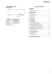
... - BACK PANEL - MODEL US AEP CND PART No. 4-253-299-0s 4-253-299-1s 4-253-299-3s • Abbreviation CND: Canadian model STR-DE197 TABLE OF CONTENTS 1. GENERAL Main unit 4 Remote button description 6 2. DIAGRAMS 4-1. IC Pin Description 11 4-2. Printed Wiring Boards - Main Section 17 4-6. Schematic Diagram - Schematic Diagram - Printed Wiring Boards - Panel Section...
... - BACK PANEL - MODEL US AEP CND PART No. 4-253-299-0s 4-253-299-1s 4-253-299-3s • Abbreviation CND: Canadian model STR-DE197 TABLE OF CONTENTS 1. GENERAL Main unit 4 Remote button description 6 2. DIAGRAMS 4-1. IC Pin Description 11 4-2. Printed Wiring Boards - Main Section 17 4-6. Schematic Diagram - Schematic Diagram - Printed Wiring Boards - Panel Section...

Service Manual
Page 11
... 53 BASS B. IC PIN DESCRIPTION • IC201 µPD78045FGF-134-3B9 (SYSTEM CONTROLLER, FL DISPLAY DRIVER) Pin No. A/D converter power supply pin (+5 V) 30 AV.REF - Not used . (Open) 52 +5V - A/D converter reference voltage input (+5 V) 31 - - Not used . (Open) 33 GND - Power supply... signal input 18 TUNED I TUNED indicator detection signal input from remote control receiver IC. 50 TUNER MUTE O Muting control signal output to the vacuum fluorescent display (FL201). 8 +5V - SECTION 4 DIAGRAMS STR-DE197 4-1. Pin Name I Sircs signal input from FM/AM tuner pack...
... 53 BASS B. IC PIN DESCRIPTION • IC201 µPD78045FGF-134-3B9 (SYSTEM CONTROLLER, FL DISPLAY DRIVER) Pin No. A/D converter power supply pin (+5 V) 30 AV.REF - Not used . (Open) 52 +5V - A/D converter reference voltage input (+5 V) 31 - - Not used . (Open) 33 GND - Power supply... signal input 18 TUNED I TUNED indicator detection signal input from remote control receiver IC. 50 TUNER MUTE O Muting control signal output to the vacuum fluorescent display (FL201). 8 +5V - SECTION 4 DIAGRAMS STR-DE197 4-1. Pin Name I Sircs signal input from FM/AM tuner pack...

Service Manual
Page 15
...9L SOUND CONTROL IC401 REC L 32 CD L 7 VOL L 29 MD L 5 VIDEO 2 3 TREBLE L MIDDLE L BASS L OUT L 20 VIDEO 1 1 CONTROL 15 14 CLK DATA CLK DATA STB STR-DE197 AUDIO AMP IC403 3 1 ELECTRONIC VOLUME IC402 L 3 IN L OUT 2 VOLUME CONTROL 8 9 10 VIDEO 1,MD/TAPE SELECT IC404 1 2 4 3 13 5 Q474 INV. J801 (2/2) -3 L R-CH -4...STEREO TUNED TUNER MUTE CE DO DI CL VOL A VOL B X1 X2 SIRCS 38 39 13 RV201 MASTER VOLUME 34 35 49 71 X201 4.19MHz 1 REMOTE CONTROL RECEIVER IC202 -24V 77 - 72,70 - 62 7 - 1,80 - 78 FL201 VACUUM FLUORESCENT DISPLAY F1 F2 VLOAD S 1 I S15 DIG1 I DIG10 ...
...9L SOUND CONTROL IC401 REC L 32 CD L 7 VOL L 29 MD L 5 VIDEO 2 3 TREBLE L MIDDLE L BASS L OUT L 20 VIDEO 1 1 CONTROL 15 14 CLK DATA CLK DATA STB STR-DE197 AUDIO AMP IC403 3 1 ELECTRONIC VOLUME IC402 L 3 IN L OUT 2 VOLUME CONTROL 8 9 10 VIDEO 1,MD/TAPE SELECT IC404 1 2 4 3 13 5 Q474 INV. J801 (2/2) -3 L R-CH -4...STEREO TUNED TUNER MUTE CE DO DI CL VOL A VOL B X1 X2 SIRCS 38 39 13 RV201 MASTER VOLUME 34 35 49 71 X201 4.19MHz 1 REMOTE CONTROL RECEIVER IC202 -24V 77 - 72,70 - 62 7 - 1,80 - 78 FL201 VACUUM FLUORESCENT DISPLAY F1 F2 VLOAD S 1 I S15 DIG1 I DIG10 ...


