
Operating Instructions
Page 3
About This Manual Note for the supplied remote For RM-U185 About area codes AC OUTLET 4-XXX-XXX-XX AA 3GB
About This Manual Note for the supplied remote For RM-U185 About area codes AC OUTLET 4-XXX-XXX-XX AA 3GB

Operating Instructions
Page 4
Table of Contents Getting Started Amplifier Operation Operations Using the Remote RM-U185 Additional Information Other Operations 4GB
Table of Contents Getting Started Amplifier Operation Operations Using the Remote RM-U185 Additional Information Other Operations 4GB

Operating Instructions
Page 12
Presetting radio stations Presetting radio stations 1 2 3 4 5 Tuning to preset stations 1 2 tA1yA2y...yA0yB1yB2y...yB0T tC0y...yC2yC1T Using the remote 1 2 To select the preset station directly 6 Note 12GB
Presetting radio stations Presetting radio stations 1 2 3 4 5 Tuning to preset stations 1 2 tA1yA2y...yA0yB1yB2y...yB0T tC0y...yC2yC1T Using the remote 1 2 To select the preset station directly 6 Note 12GB
Operating Instructions
Page 19
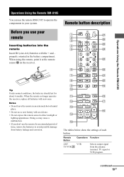
L BALANCE R BASS BOOST qa qk - qg w; 19GB Operations Using the Remote RM-U185 Before you use your remote Inserting batteries into the remote Tip Notes Remote button description SLEEP AV ?/1 ?/1 1 wj 2 SYSTEM STANDBY wh 3 VIDEO 1 VIDEO 2 DVD • wg 4 MD/TAPE CD TUNER 5 wf TOP MENU 1 DVD MENU F 23 G ENTER g 4 56 wd f O 7 89 6 7 8 SHIFT >10 0 - /- - - TUNING ENTER RETURN TV/VIDEO ANT TV/VTR D.SKIP ws wa w; 9 N X x ql q; TREBLE + MUTING qs qj qd - CH/PRESET + .> m M D. BASS + MASTER VOL + + qh qf TV VOL TV CH - -
L BALANCE R BASS BOOST qa qk - qg w; 19GB Operations Using the Remote RM-U185 Before you use your remote Inserting batteries into the remote Tip Notes Remote button description SLEEP AV ?/1 ?/1 1 wj 2 SYSTEM STANDBY wh 3 VIDEO 1 VIDEO 2 DVD • wg 4 MD/TAPE CD TUNER 5 wf TOP MENU 1 DVD MENU F 23 G ENTER g 4 56 wd f O 7 89 6 7 8 SHIFT >10 0 - /- - - TUNING ENTER RETURN TV/VIDEO ANT TV/VTR D.SKIP ws wa w; 9 N X x ql q; TREBLE + MUTING qs qj qd - CH/PRESET + .> m M D. BASS + MASTER VOL + + qh qf TV VOL TV CH - -

Operating Instructions
Page 25
Remote control Error message If you are unable to remedy the problem using the troubleshooting guide If the problem persist 25GB
Remote control Error message If you are unable to remedy the problem using the troubleshooting guide If the problem persist 25GB

Service Manual
Page 2
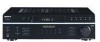
STR-DE197 AM tuner section Tuning range Models of ...including projecting parts and controls 7.0 kg (15 lb 7 oz) Supplied accessories FM wire antenna (1) AM loop antenna (1) Remote commander RM-U185 (1) R6 (size-AA) batteries (2) Design and specifications are subject to change without notice. •... CES COMPOSANTS QUE PAR DES PIÈCES SONY DONT LES NUMÉROS SONT DONNÉS DANS CE MANUEL OU DANS LES... tuning in any exposed metal part to earth ground and from any AM station, turn off the receiver. The "limit" indication is 0.75 V, so analog meters must not exceed 0.5 mA (500...
STR-DE197 AM tuner section Tuning range Models of ...including projecting parts and controls 7.0 kg (15 lb 7 oz) Supplied accessories FM wire antenna (1) AM loop antenna (1) Remote commander RM-U185 (1) R6 (size-AA) batteries (2) Design and specifications are subject to change without notice. •... CES COMPOSANTS QUE PAR DES PIÈCES SONY DONT LES NUMÉROS SONT DONNÉS DANS CE MANUEL OU DANS LES... tuning in any exposed metal part to earth ground and from any AM station, turn off the receiver. The "limit" indication is 0.75 V, so analog meters must not exceed 0.5 mA (500...
Service Manual
Page 3
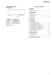
...Section (1/2 18 4-7. MODEL US AEP CND PART No. 4-253-299-0s 4-253-299-1s 4-253-299-3s • Abbreviation CND: Canadian model STR-DE197 TABLE OF CONTENTS 1. Main Board 9 3. Main Section 15 4-4. Schematic Diagram - Schematic Diagram - BACK PANEL - DISASSEMBLY 2-1. IC Pin Description 11 ... Boards - IC Block Diagrams 22 5. Chassis Section 25 6. MODEL IDENTIFICATION - Printed Wiring Boards - GENERAL Main unit 4 Remote button description 6 2. Front Panel Section 8 2-3. DIAGRAMS 4-1. Block Diagram - Block Diagram - TEST MODE 10 4. Main Section (2/2 19 4-8.
...Section (1/2 18 4-7. MODEL US AEP CND PART No. 4-253-299-0s 4-253-299-1s 4-253-299-3s • Abbreviation CND: Canadian model STR-DE197 TABLE OF CONTENTS 1. Main Board 9 3. Main Section 15 4-4. Schematic Diagram - Schematic Diagram - BACK PANEL - DISASSEMBLY 2-1. IC Pin Description 11 ... Boards - IC Block Diagrams 22 5. Chassis Section 25 6. MODEL IDENTIFICATION - Printed Wiring Boards - GENERAL Main unit 4 Remote button description 6 2. Front Panel Section 8 2-3. DIAGRAMS 4-1. Block Diagram - Block Diagram - TEST MODE 10 4. Main Section (2/2 19 4-8.

Service Manual
Page 11
... select signal input (Fixed at L in this set ) 32 OPEN - A/D converter power supply pin (+5 V) 30 AV.REF - A/D converter reference voltage input (+5 V) 31 - - SECTION 4 DIAGRAMS STR-DE197 4-1. LED O BASS BOOST LED drive signal output 54 SPK A LED O SPEAKER A LED drive signal output 55 SPK...POWER I System power signal input 45 AC MUTE O A-Class mute signal output 46 RDS INT I RDS clock signal input from remote control receiver IC. 50 TUNER MUTE O Muting control signal output to the vacuum fluorescent display (FL201). 8 +5V - Power supply pin ...
... select signal input (Fixed at L in this set ) 32 OPEN - A/D converter power supply pin (+5 V) 30 AV.REF - A/D converter reference voltage input (+5 V) 31 - - SECTION 4 DIAGRAMS STR-DE197 4-1. LED O BASS BOOST LED drive signal output 54 SPK A LED O SPEAKER A LED drive signal output 55 SPK...POWER I System power signal input 45 AC MUTE O A-Class mute signal output 46 RDS INT I RDS clock signal input from remote control receiver IC. 50 TUNER MUTE O Muting control signal output to the vacuum fluorescent display (FL201). 8 +5V - Power supply pin ...

Service Manual
Page 15
... STEREO TUNED TUNER MUTE CE DO DI CL VOL A VOL B X1 X2 SIRCS 38 39 13 RV201 MASTER VOLUME 34 35 49 71 X201 4.19MHz 1 REMOTE CONTROL RECEIVER IC202 -24V 77 - 72,70 - 62 7 - 1,80 - 78 FL201 VACUUM FLUORESCENT DISPLAY F1 F2 VLOAD S 1 I S15 DIG1 I DIG10 AD1 AD2 AD3 AD4 AD5 SYSTEM... SIGNAL • Signal path : TUNER (FM/AM) : VIDEO (AUDIO) : CD (ANALOG) • R-ch is omitted due to same as L-ch. • Abbreviation CND : Canadian model STR-DE197 15 15 BLOCK DIAGRAM - TN1 FM/AM TUNER PACK 10V +10V FM 75Ω COAXIAL ANTENNA AM L CH R CH MUTE CE CLOCK DATA DO TUNED...
... STEREO TUNED TUNER MUTE CE DO DI CL VOL A VOL B X1 X2 SIRCS 38 39 13 RV201 MASTER VOLUME 34 35 49 71 X201 4.19MHz 1 REMOTE CONTROL RECEIVER IC202 -24V 77 - 72,70 - 62 7 - 1,80 - 78 FL201 VACUUM FLUORESCENT DISPLAY F1 F2 VLOAD S 1 I S15 DIG1 I DIG10 AD1 AD2 AD3 AD4 AD5 SYSTEM... SIGNAL • Signal path : TUNER (FM/AM) : VIDEO (AUDIO) : CD (ANALOG) • R-ch is omitted due to same as L-ch. • Abbreviation CND : Canadian model STR-DE197 15 15 BLOCK DIAGRAM - TN1 FM/AM TUNER PACK 10V +10V FM 75Ω COAXIAL ANTENNA AM L CH R CH MUTE CE CLOCK DATA DO TUNED...


