Operating Instructions
Page 13
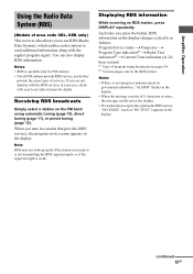
Using the Radio Data System (RDS) (Models of area code CEL, CEK only) Displaying RDS information Notes t t t t Notes Receiving RDS broadcasts Note 13GB
Using the Radio Data System (RDS) (Models of area code CEL, CEK only) Displaying RDS information Notes t t t t Notes Receiving RDS broadcasts Note 13GB

Service Manual
Page 1
... tone b ypassed). 3) Weighted netw ork, input le vel. FM STEREO/FM-AM RECEIVER 9-877-864-06 2007E04-1 © 2007. 05 Sony Corporation Home Audio Division Published by Sony Techno Create Corporation 1 Continued on next page - SERVICE MANUAL Ver. 1.5 2007. 05 STR-DE197 US Model Canadian Model AEP Model AUDIO POWER SPECIFICATIONS POWER OUTPUT AND TOTAL...
... tone b ypassed). 3) Weighted netw ork, input le vel. FM STEREO/FM-AM RECEIVER 9-877-864-06 2007E04-1 © 2007. 05 Sony Corporation Home Audio Division Published by Sony Techno Create Corporation 1 Continued on next page - SERVICE MANUAL Ver. 1.5 2007. 05 STR-DE197 US Model Canadian Model AEP Model AUDIO POWER SPECIFICATIONS POWER OUTPUT AND TOTAL...

Service Manual
Page 2
... the voltage drop across a resistor by any exposed metal part having a return to earth ground and from any AM station, turn off the receiver. SAFETY-RELATED COMPONENT WARNING!! STR-DE197 AM tuner section Tuning range Models of area code US, CND With 10-kHz tuning scale: 530 - 1,710 kHz 4) With 9-kHz tuning scale... MARK 0 ON THE SCHEMATIC DIAGRAMS AND IN THE PARTS LIST ARE CRITICAL TO SAFE OPERATION. NE REMPLACER CES COMPOSANTS QUE PAR DES PIÈCES SONY DONT LES NUMÉROS SONT DONNÉS DANS CE MANUEL OU DANS LES SUPPLÉMENTS PUBLIÉS PAR...
... the voltage drop across a resistor by any exposed metal part having a return to earth ground and from any AM station, turn off the receiver. SAFETY-RELATED COMPONENT WARNING!! STR-DE197 AM tuner section Tuning range Models of area code US, CND With 10-kHz tuning scale: 530 - 1,710 kHz 4) With 9-kHz tuning scale... MARK 0 ON THE SCHEMATIC DIAGRAMS AND IN THE PARTS LIST ARE CRITICAL TO SAFE OPERATION. NE REMPLACER CES COMPOSANTS QUE PAR DES PIÈCES SONY DONT LES NUMÉROS SONT DONNÉS DANS CE MANUEL OU DANS LES SUPPLÉMENTS PUBLIÉS PAR...

Service Manual
Page 10
...than the function buttons to turn on the main power. 2. The message "AUTO-BETICAL SELECT" are displayed for a moment and the receiver starts scanning. ING/CHAR +] button, press the ?/1 button to turn on the main power. 2. Procedure: 1. The destination and ...buttons simultaneously, press the ?/1 button to release the check mode. Software Version Display Mode The software version is activated, all light off 3. STR-DE197 SECTION 3 TEST MODE Fluorescent Indicator Tube Test Mode All fluorescent segments are pressed. • Operation of RDS station. ex.) US, Canadian ...
...than the function buttons to turn on the main power. 2. The message "AUTO-BETICAL SELECT" are displayed for a moment and the receiver starts scanning. ING/CHAR +] button, press the ?/1 button to turn on the main power. 2. Procedure: 1. The destination and ...buttons simultaneously, press the ?/1 button to release the check mode. Software Version Display Mode The software version is activated, all light off 3. STR-DE197 SECTION 3 TEST MODE Fluorescent Indicator Tube Test Mode All fluorescent segments are pressed. • Operation of RDS station. ex.) US, Canadian ...

Service Manual
Page 11
Not used . (Open) 33 GND - SECTION 4 DIAGRAMS STR-DE197 4-1. Ground 34 X1 I Master clock input (4.19 MHz) 35 X2 O ... pack. 19 STEREO I Master volume JOG data input A, B 40 FUNC.MUTE O Not used . (Connect to AV.REF pin in this set ) 41 CK O Serial clock signal output to electronic volume IC. 42 DATA O Serial...Pin No. A/D converter power supply pin (+5 V) 30 AV.REF - Not used . (Fixed at H: US, Canadian model, L: AEP model) FM/AM signal meter voltage detection signal input from remote control receiver IC. 50 TUNER MUTE O Muting control signal output ...
Not used . (Open) 33 GND - SECTION 4 DIAGRAMS STR-DE197 4-1. Ground 34 X1 I Master clock input (4.19 MHz) 35 X2 O ... pack. 19 STEREO I Master volume JOG data input A, B 40 FUNC.MUTE O Not used . (Connect to AV.REF pin in this set ) 41 CK O Serial clock signal output to electronic volume IC. 42 DATA O Serial...Pin No. A/D converter power supply pin (+5 V) 30 AV.REF - Not used . (Fixed at H: US, Canadian model, L: AEP model) FM/AM signal meter voltage detection signal input from remote control receiver IC. 50 TUNER MUTE O Muting control signal output ...

Service Manual
Page 15
... TUNER MUTE CE DO DI CL VOL A VOL B X1 X2 SIRCS 38 39 13 RV201 MASTER VOLUME 34 35 49 71 X201 4.19MHz 1 REMOTE CONTROL RECEIVER IC202 -24V 77 - 72,70 - 62 7 - 1,80 - 78 FL201 VACUUM FLUORESCENT DISPLAY F1 F2 VLOAD S 1 I S15 DIG1 I DIG10 AD1 AD2 AD3 AD4 AD5 SYSTEM CONTROLLER... SIGNAL • Signal path : TUNER (FM/AM) : VIDEO (AUDIO) : CD (ANALOG) • R-ch is omitted due to same as L-ch. • Abbreviation CND : Canadian model STR-DE197 15 15 MAIN SECTION - TN1 FM/AM TUNER PACK 10V +10V FM 75Ω COAXIAL ANTENNA AM L CH R CH MUTE CE CLOCK DATA DO TUNED...
... TUNER MUTE CE DO DI CL VOL A VOL B X1 X2 SIRCS 38 39 13 RV201 MASTER VOLUME 34 35 49 71 X201 4.19MHz 1 REMOTE CONTROL RECEIVER IC202 -24V 77 - 72,70 - 62 7 - 1,80 - 78 FL201 VACUUM FLUORESCENT DISPLAY F1 F2 VLOAD S 1 I S15 DIG1 I DIG10 AD1 AD2 AD3 AD4 AD5 SYSTEM CONTROLLER... SIGNAL • Signal path : TUNER (FM/AM) : VIDEO (AUDIO) : CD (ANALOG) • R-ch is omitted due to same as L-ch. • Abbreviation CND : Canadian model STR-DE197 15 15 MAIN SECTION - TN1 FM/AM TUNER PACK 10V +10V FM 75Ω COAXIAL ANTENNA AM L CH R CH MUTE CE CLOCK DATA DO TUNED...


