Operating Instructions
Page 1
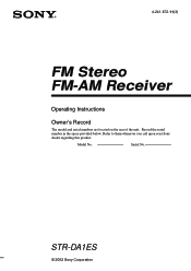
Refer to them whenever you call upon your Sony dealer regarding this product. Record the serial number in the space provided below. Model No. STR-DA1ES © 2002 Sony Corporation Serial No. 4-241-672-11(3) FM Stereo FM-AM Receiver Operating Instructions Owner's Record The model and serial numbers are located on the rear of the unit.
Refer to them whenever you call upon your Sony dealer regarding this product. Record the serial number in the space provided below. Model No. STR-DA1ES © 2002 Sony Corporation Serial No. 4-241-672-11(3) FM Stereo FM-AM Receiver Operating Instructions Owner's Record The model and serial numbers are located on the rear of the unit.
Operating Instructions
Page 2
... it correctly as vases, on a circuit different from that this equipment does cause harmful interference to radio or television reception, which the receiver is a U.S. Don't throw away the battery with news papers, table-cloths, curtains, etc. These limits are cautioned that any changes...a bookcase or built-in cabinet. Connect the equipment into an outlet on the apparatus. registered mark. As an ENERGY STAR® partner, Sony Corporation has determined that to the presence of the following measures: - ENERGY STAR® is connected. - And don't place lighted candles ...
... it correctly as vases, on a circuit different from that this equipment does cause harmful interference to radio or television reception, which the receiver is a U.S. Don't throw away the battery with news papers, table-cloths, curtains, etc. These limits are cautioned that any changes...a bookcase or built-in cabinet. Connect the equipment into an outlet on the apparatus. registered mark. As an ENERGY STAR® partner, Sony Corporation has determined that to the presence of the following measures: - ENERGY STAR® is connected. - And don't place lighted candles ...
Operating Instructions
Page 3
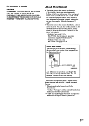
... Logic Surround and the DTS** Digital Surround System. * Manufactured under license from Dolby Laboratories. For customers in this manual describe the controls on the receiver. Any difference in the text, for illustration purposes unless stated otherwise. Models of other area codes RM-U305C: See pages 53-56. Models of...for example, "Models of area code AA only". In this manual, the Models of area code U is clearly indicated in the text, for model STR-DA1ES. For details on the use the controls on the supplied remote if they have the same or similar names as those on the lower portion...
... Logic Surround and the DTS** Digital Surround System. * Manufactured under license from Dolby Laboratories. For customers in this manual describe the controls on the receiver. Any difference in the text, for illustration purposes unless stated otherwise. Models of other area codes RM-U305C: See pages 53-56. Models of...for example, "Models of area code AA only". In this manual, the Models of area code U is clearly indicated in the text, for model STR-DA1ES. For details on the use the controls on the supplied remote if they have the same or similar names as those on the lower portion...

Operating Instructions
Page 8
... of area code CEL, CEK. 8GB Connectable components Component to connect each component. Getting Started 1: Check how to hookup your components Steps 1a through this receiver. This connection is used to output the audio decoded by the component's internal multi-channel decoder through 1c beginning on page 10 describe how to...
... of area code CEL, CEK. 8GB Connectable components Component to connect each component. Getting Started 1: Check how to hookup your components Steps 1a through this receiver. This connection is used to output the audio decoded by the component's internal multi-channel decoder through 1c beginning on page 10 describe how to...

Operating Instructions
Page 11
... ANTENNA Y DVD/LD OPTICAL IN TV/SAT OPTICAL IN MD/TAPE OPTICAL IN MD/TAPE OPTICAL OUT ASSIGNABLE COAXIAL IN ( ) DVD/LD CD/SACD AM U FM 75Ω COAXIAL S-VIDEO OUT VIDEO S-VIDEO IN VIDEO S-VIDEO IN VIDEO OUT VIDEO CONTROL AUDIO MONITOR A1 IN L AUDIO IN AUDIO OUT IN VIDEO... MD/TAPE + R - continued 11GB Getting Started 2 Connect the video jacks. (Except for models of your TV by connecting your TV's audio output jacks to the receiver as shown above. Note On this case, do not connect the TV's video output jack to the TV/SAT VIDEO IN jack on the...
... ANTENNA Y DVD/LD OPTICAL IN TV/SAT OPTICAL IN MD/TAPE OPTICAL IN MD/TAPE OPTICAL OUT ASSIGNABLE COAXIAL IN ( ) DVD/LD CD/SACD AM U FM 75Ω COAXIAL S-VIDEO OUT VIDEO S-VIDEO IN VIDEO S-VIDEO IN VIDEO OUT VIDEO CONTROL AUDIO MONITOR A1 IN L AUDIO IN AUDIO OUT IN VIDEO... MD/TAPE + R - continued 11GB Getting Started 2 Connect the video jacks. (Except for models of your TV by connecting your TV's audio output jacks to the receiver as shown above. Note On this case, do not connect the TV's video output jack to the TV/SAT VIDEO IN jack on the...

Operating Instructions
Page 12
...ANTENNA Y DVD/LD OPTICAL IN TV/SAT OPTICAL IN MD/TAPE OPTICAL IN MD/TAPE OPTICAL OUT ASSIGNABLE COAXIAL IN ( ) DVD/LD CD/SACD AM U FM 75Ω COAXIAL S-VIDEO OUT VIDEO S-VIDEO IN VIDEO S-VIDEO IN VIDEO OUT VIDEO IN VIDEO S-VIDEO S-VIDEO OUT IN VIDEO VIDEO PB/CB /B-Y CONTROL...the RF demodulator. Refer to the ASSIGNABLE COAXIAL IN (DVD/LD CD/SACD) jack on the required cords (A-H), see page 9. Connect the player to this receiver. Refer to the operating instructions supplied with a DOLBY DIGITAL RF OUT jack via an RF demodulator (You cannot connect an LD player's DOLBY DIGITAL RF...
...ANTENNA Y DVD/LD OPTICAL IN TV/SAT OPTICAL IN MD/TAPE OPTICAL IN MD/TAPE OPTICAL OUT ASSIGNABLE COAXIAL IN ( ) DVD/LD CD/SACD AM U FM 75Ω COAXIAL S-VIDEO OUT VIDEO S-VIDEO IN VIDEO S-VIDEO IN VIDEO OUT VIDEO IN VIDEO S-VIDEO S-VIDEO OUT IN VIDEO VIDEO PB/CB /B-Y CONTROL...the RF demodulator. Refer to the ASSIGNABLE COAXIAL IN (DVD/LD CD/SACD) jack on the required cords (A-H), see page 9. Connect the player to this receiver. Refer to the operating instructions supplied with a DOLBY DIGITAL RF OUT jack via an RF demodulator (You cannot connect an LD player's DOLBY DIGITAL RF...
Operating Instructions
Page 13
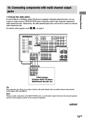
...CH OUT WOOFER DVD/LD player, CD/Super Audio CD player, Multichannel decoder, etc. Alternatively, the multi channel input jacks can connect it to this receiver's MULTI CH IN jacks to connect an external multi channel decoder. For details on the connected component. continued 13GB If your DVD/LD or CD...ANTENNA Y DVD/LD OPTICAL IN TV/SAT OPTICAL IN MD/TAPE OPTICAL IN MD/TAPE OPTICAL OUT ASSIGNABLE COAXIAL IN ( ) DVD/LD CD/SACD AM U FM 75Ω COAXIAL S-VIDEO OUT VIDEO S-VIDEO S-VIDEO IN IN OUT VIDEO VIDEO VIDEO IN VIDEO S-VIDEO S-VIDEO OUT IN VIDEO VIDEO PB/CB /B-Y ...
...CH OUT WOOFER DVD/LD player, CD/Super Audio CD player, Multichannel decoder, etc. Alternatively, the multi channel input jacks can connect it to this receiver's MULTI CH IN jacks to connect an external multi channel decoder. For details on the connected component. continued 13GB If your DVD/LD or CD...ANTENNA Y DVD/LD OPTICAL IN TV/SAT OPTICAL IN MD/TAPE OPTICAL IN MD/TAPE OPTICAL OUT ASSIGNABLE COAXIAL IN ( ) DVD/LD CD/SACD AM U FM 75Ω COAXIAL S-VIDEO OUT VIDEO S-VIDEO S-VIDEO IN IN OUT VIDEO VIDEO VIDEO IN VIDEO S-VIDEO S-VIDEO OUT IN VIDEO VIDEO PB/CB /B-Y ...

Operating Instructions
Page 14
... signals cannot be converted to S-video or standard video signals (or vice versa). Note You can connect the component to the S-VIDEO jacks on the receiver. Connecting a TV with COMPONENT VIDEO (Y, B-Y, R-Y) output jacks. TV monitor INPUT VIDEO INPUT S VIDEO INPUT COMPONENT R-Y B-Y Y CD H DVD/LD player OUTPUT COMPONENT R-Y ...LD OPTICAL IN TV/SAT OPTICAL IN MD/TAPE OPTICAL IN MD/TAPE OPTICAL OUT ASSIGNABLE COAXIAL IN ( ) DVD/LD CD/SACD AM U FM 75Ω COAXIAL S-VIDEO OUT VIDEO S-VIDEO IN VIDEO S-VIDEO IN VIDEO OUT VIDEO IN VIDEO S-VIDEO S-VIDEO OUT IN VIDEO VIDEO PB...
... signals cannot be converted to S-video or standard video signals (or vice versa). Note You can connect the component to the S-VIDEO jacks on the receiver. Connecting a TV with COMPONENT VIDEO (Y, B-Y, R-Y) output jacks. TV monitor INPUT VIDEO INPUT S VIDEO INPUT COMPONENT R-Y B-Y Y CD H DVD/LD player OUTPUT COMPONENT R-Y ...LD OPTICAL IN TV/SAT OPTICAL IN MD/TAPE OPTICAL IN MD/TAPE OPTICAL OUT ASSIGNABLE COAXIAL IN ( ) DVD/LD CD/SACD AM U FM 75Ω COAXIAL S-VIDEO OUT VIDEO S-VIDEO IN VIDEO S-VIDEO IN VIDEO OUT VIDEO IN VIDEO S-VIDEO S-VIDEO OUT IN VIDEO VIDEO PB...

Operating Instructions
Page 16
... equipped with only analog audio jacks (continued) Hooking up video components If you connect your TV's audio output jacks to the S-VIDEO jacks on the receiver. Note You can listen to the sound of your TV by connecting your TV to the MONITOR jacks, you can connect the component to the... AUDIO IN AUDIO OUT AUDIO IN AUDIO OUT AUDIO IN MONITOR TV/SAT DVD/LD OUT IN IN IN COMPONENT VIDEO L L MD/TAPE OPTICAL OUT FM 75Ω COAXIAL R ASSIGNABLE IN R SURROUND COAXIAL IN ( ) DVD/LD CD/SACD TV/SAT DVD/LD VIDEO 2 VIDEO 1 L FRONT SURROUND CENTER IN U L SIGNAL GND IN...
... equipped with only analog audio jacks (continued) Hooking up video components If you connect your TV's audio output jacks to the S-VIDEO jacks on the receiver. Note You can listen to the sound of your TV by connecting your TV to the MONITOR jacks, you can connect the component to the... AUDIO IN AUDIO OUT AUDIO IN AUDIO OUT AUDIO IN MONITOR TV/SAT DVD/LD OUT IN IN IN COMPONENT VIDEO L L MD/TAPE OPTICAL OUT FM 75Ω COAXIAL R ASSIGNABLE IN R SURROUND COAXIAL IN ( ) DVD/LD CD/SACD TV/SAT DVD/LD VIDEO 2 VIDEO 1 L FRONT SURROUND CENTER IN U L SIGNAL GND IN...

Operating Instructions
Page 17
...ANTENNA Y DVD/LD OPTICAL IN TV/SAT OPTICAL IN MD/TAPE OPTICAL IN MD/TAPE OPTICAL OUT ASSIGNABLE COAXIAL IN ( ) DVD/LD CD/SACD AM U FM 75Ω COAXIAL S-VIDEO OUT VIDEO S-VIDEO IN VIDEO S-VIDEO IN VIDEO OUT VIDEO IN VIDEO S-VIDEO S-VIDEO OUT IN VIDEO VIDEO PB/CB /B-Y ... + R - SPEA IMPEDANCE Notes • To prevent noise pickup, keep the AM loop antenna away from the receiver and other components. • Be sure to fully extend the FM wire antenna. • After connecting the FM wire antenna, keep it as horizontal as possible. • Do not use the U SIGNAL GND terminal for...
...ANTENNA Y DVD/LD OPTICAL IN TV/SAT OPTICAL IN MD/TAPE OPTICAL IN MD/TAPE OPTICAL OUT ASSIGNABLE COAXIAL IN ( ) DVD/LD CD/SACD AM U FM 75Ω COAXIAL S-VIDEO OUT VIDEO S-VIDEO IN VIDEO S-VIDEO IN VIDEO OUT VIDEO IN VIDEO S-VIDEO S-VIDEO OUT IN VIDEO VIDEO PB/CB /B-Y ... + R - SPEA IMPEDANCE Notes • To prevent noise pickup, keep the AM loop antenna away from the receiver and other components. • Be sure to fully extend the FM wire antenna. • After connecting the FM wire antenna, keep it as horizontal as possible. • Do not use the U SIGNAL GND terminal for...
Operating Instructions
Page 18
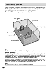
.... Note Be sure to turn the power off before adjusting the IMPEDANCE SELECTOR. 18GB Refer to the operating instructions supplied with your speakers to the receiver. This receiver alows you want. To fully enjoy theater-like multi channel surround sound requires five speakers (two front speakers, a center speaker, and two surround speakers...
.... Note Be sure to turn the power off before adjusting the IMPEDANCE SELECTOR. 18GB Refer to the operating instructions supplied with your speakers to the receiver. This receiver alows you want. To fully enjoy theater-like multi channel surround sound requires five speakers (two front speakers, a center speaker, and two surround speakers...
Operating Instructions
Page 20
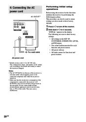
... power cord * Models of AC outlets vary according to the model and country to which supplies power to the connected component only while the receiver is shipped. This procedure can also be used to return settings you have made to their factory settings. • All settings in the ...connect high-wattage electrical home appliances such as electric irons, fans, or TVs to turn off the receiver. 2 Hold down ?/1 for the first time, initialize the receiver by performing the following are reset to the receiver's AC OUTLET(s) does not exceed the wattage stated on . • Make sure that the ...
... power cord * Models of AC outlets vary according to the model and country to which supplies power to the connected component only while the receiver is shipped. This procedure can also be used to return settings you have made to their factory settings. • All settings in the ...connect high-wattage electrical home appliances such as electric irons, fans, or TVs to turn off the receiver. 2 Hold down ?/1 for the first time, initialize the receiver by performing the following are reset to the receiver's AC OUTLET(s) does not exceed the wattage stated on . • Make sure that the ...
Operating Instructions
Page 21
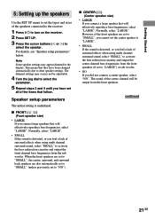
... is underlined. However, if the front speakers are also automatically set to "SMALL" (unless previously set all of the speakers connected to the receiver. 1 Press ?/1 to turn on the receiver. 2 Press SET UP. 3 Press the cursor buttons ( or ) to select the speaker. This means that will be adjustable. 4 Turn the jog dial...
... is underlined. However, if the front speakers are also automatically set to "SMALL" (unless previously set all of the speakers connected to the receiver. 1 Press ?/1 to turn on the receiver. 2 Press SET UP. 3 Press the cursor buttons ( or ) to select the speaker. This means that will be adjustable. 4 Turn the jog dial...
Operating Instructions
Page 23
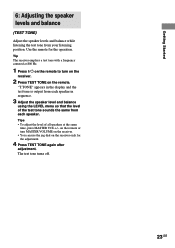
...listening position. "T.TONE" appears in the display and the test tone is output from each speaker. The test tone turns off. 23GB Tip The receiver employs a test tone with a frequency centered at the same time, press MASTER VOL +/- Use the remote for the adjustment. 4 Press TEST ...TONE again after adjustment. on the remote or turn on the receiver. 2 Press TEST TONE on the receiver only for the operation. Getting Started 6: Adjusting the speaker levels and balance (TEST TONE) Adjust the speaker levels and balance ...
...listening position. "T.TONE" appears in the display and the test tone is output from each speaker. The test tone turns off. 23GB Tip The receiver employs a test tone with a frequency centered at the same time, press MASTER VOL +/- Use the remote for the adjustment. 4 Press TEST ...TONE again after adjustment. on the remote or turn on the receiver. 2 Press TEST TONE on the receiver only for the operation. Getting Started 6: Adjusting the speaker levels and balance (TEST TONE) Adjust the speaker levels and balance ...

Operating Instructions
Page 24
... you select a component which is canceled when you selected. To turn on the component and start playback. The selected audio source is connected to the receiver's MONITOR jack, the video from the components connected to enjoy high quality analog sources like DVD or Super Audio CD. Note This function is also...
... you select a component which is canceled when you selected. To turn on the component and start playback. The selected audio source is connected to the receiver's MONITOR jack, the video from the components connected to enjoy high quality analog sources like DVD or Super Audio CD. Note This function is also...

Operating Instructions
Page 25
... AM broadcasts through the built-in an AM station, adjust the direction of poor FM stereo reception Press FM MODE to switch to TUNER. If the FM stereo reception is not used in the display, select the monaural audio so that the sound will be changed (see page 17). If the ... 3 and 4. For details on the remote. press - to scan from low to select the FM or AM band. 3 Press TUNING + or - (TUNING/PTY SELECT + or - The receiver stops scanning whenever a station is set to select the FM or AM band. 3 Press D.TUNING. 4 Select the numbers for optimum reception. Tip The tuning...
... AM broadcasts through the built-in an AM station, adjust the direction of poor FM stereo reception Press FM MODE to switch to TUNER. If the FM stereo reception is not used in the display, select the monaural audio so that the sound will be changed (see page 17). If the ... 3 and 4. For details on the remote. press - to scan from low to select the FM or AM band. 3 Press TUNING + or - (TUNING/PTY SELECT + or - The receiver stops scanning whenever a station is set to select the FM or AM band. 3 Press D.TUNING. 4 Select the numbers for optimum reception. Tip The tuning...
Operating Instructions
Page 26
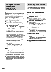
...same program, then stores only the one , see "Presetting radio stations". 1 Press ?/1 to turn the receiver back on tuning the stored stations, see page 28. Regular FM stations are sorted alphabetically by one with the clearest signal. The selected RDS stations are assigned 2-character preset ...normal operation. Additionally, it only stores the stations with this procedure to turn off the receiver. 2 Hold down MEMORY and press ?/1 to store stations in the display momentarily and the receiver returns to 30 FM or AM stations. When done, "FINISH" appears in your new area. • ...
...same program, then stores only the one , see "Presetting radio stations". 1 Press ?/1 to turn the receiver back on tuning the stored stations, see page 28. Regular FM stations are sorted alphabetically by one with the clearest signal. The selected RDS stations are assigned 2-character preset ...normal operation. Additionally, it only stores the stations with this procedure to turn off the receiver. 2 Hold down MEMORY and press ?/1 to store stations in the display momentarily and the receiver returns to 30 FM or AM stations. When done, "FINISH" appears in your new area. • ...
Operating Instructions
Page 27
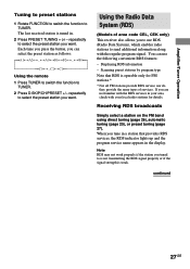
... is tuned in your area, check with your local radio stations for FM stations.* * Not all FM stations provide RDS service, nor do they provide the same types of area code CEL, CEK only) This receiver also allows you are not familiar with the regular program signal. continued... to preset stations 1 Rotate FUNCTION to switch the function to select the preset station you want . The last received station is operable only for details. Receiving RDS broadcasts Simply select a station on the FM band using direct tuning (page 26), automatic tuning (page 25), or preset tuning (page 27).
... is tuned in your area, check with your local radio stations for FM stations.* * Not all FM stations provide RDS service, nor do they provide the same types of area code CEL, CEK only) This receiver also allows you are not familiar with the regular program signal. continued... to preset stations 1 Rotate FUNCTION to switch the function to select the preset station you want . The last received station is operable only for details. Receiving RDS broadcasts Simply select a station on the FM band using direct tuning (page 26), automatic tuning (page 25), or preset tuning (page 27).

Operating Instructions
Page 28
...also appears for the information on the display changes cyclically as "NO CT") appears in the display. 28GB See the table below for non-RDS FM stations. Scanning preset stations by government authorities, "ALARM" flashes in the display. • If a station does not provide a particular RDS ... it is an emergency announcement by program type You can tune in preset stations according to select the program type. When the receiver finds a station, the receiver stops scanning. Each time you specify. b) Type of the data. Any change in this rate is scanning stations, "PTY"...
...also appears for the information on the display changes cyclically as "NO CT") appears in the display. 28GB See the table below for non-RDS FM stations. Scanning preset stations by government authorities, "ALARM" flashes in the display. • If a station does not provide a particular RDS ... it is an emergency announcement by program type You can tune in preset stations according to select the program type. When the receiver finds a station, the receiver stops scanning. Each time you specify. b) Type of the data. Any change in this rate is scanning stations, "PTY"...

Operating Instructions
Page 31
... and surround speakers are input. Multi channel surround sound is downmixed and output from the front 2 channels. 8 Tuner indicators: Light up when using the receiver to output the center and surround channel signals. qa MULTI CH IN: Lights up when adjusting the level of the front channels. 2 SLEEP: Lights up... Pro Logic processing to 2 channel signals in order to tune in the display 1 23 4 5 67 8 SLEEP a DIGITAL PRO LOGIC DTS MPEG STEREO MONO RDS SW SP. See pages 25-29 for tuner operations. 9 EQ: Lights up when the equalizer is functioning. 0 D.RANGE: Lights up when sub ...
... and surround speakers are input. Multi channel surround sound is downmixed and output from the front 2 channels. 8 Tuner indicators: Light up when using the receiver to output the center and surround channel signals. qa MULTI CH IN: Lights up when adjusting the level of the front channels. 2 SLEEP: Lights up... Pro Logic processing to 2 channel signals in order to tune in the display 1 23 4 5 67 8 SLEEP a DIGITAL PRO LOGIC DTS MPEG STEREO MONO RDS SW SP. See pages 25-29 for tuner operations. 9 EQ: Lights up when the equalizer is functioning. 0 D.RANGE: Lights up when sub ...


