

Limited Warranty (U.S. Only)
Page 1
... General Stereo/Hifi Components/Tape Decks ® CD Players/Mini Disc Players/Audio Systems Hifi Audio LIMITED WARRANTY Sony Electronics Inc. ("Sony") warrants this Product is determined to be presented to service the Product. To obtain warranty service, you must take the Product, or deliver the Product freight prepaid, in either its option, at no charge, new or rebuilt replacements in exchange for defective parts for a period of sale...
... General Stereo/Hifi Components/Tape Decks ® CD Players/Mini Disc Players/Audio Systems Hifi Audio LIMITED WARRANTY Sony Electronics Inc. ("Sony") warrants this Product is determined to be presented to service the Product. To obtain warranty service, you must take the Product, or deliver the Product freight prepaid, in either its option, at no charge, new or rebuilt replacements in exchange for defective parts for a period of sale...
Operating Instructions
Page 3
... Started Connecting video equipment 7 Connecting the FM antenna 8 Connecting the AM antenna 8 Connecting speaker systems 9 Connecting the AC power 9 Parts identification 10 Front panel 10 Remote commander 12 Audio adjustment 14 Adjusting volume 14 Adjusting left and right sound balance 14 Reinforcing the bass 14 Selecting the speaker system 14 Selecting a Program source 15 Radio reception 16 Basic Operation Tuning in a preset station - Station preset 18 Tuning in a station directly - Index input 20 Selecting a station among the preset stations having...
... Started Connecting video equipment 7 Connecting the FM antenna 8 Connecting the AM antenna 8 Connecting speaker systems 9 Connecting the AC power 9 Parts identification 10 Front panel 10 Remote commander 12 Audio adjustment 14 Adjusting volume 14 Adjusting left and right sound balance 14 Reinforcing the bass 14 Selecting the speaker system 14 Selecting a Program source 15 Radio reception 16 Basic Operation Tuning in a preset station - Station preset 18 Tuning in a station directly - Index input 20 Selecting a station among the preset stations having...

Operating Instructions
Page 4
...,792, and 3.959,590. Tuner • Precise tuning is a FM Stereo/FM-AM receiver and audio/video control center. Display • The frequency of surround effect. • 00lDaum@unmans*I • - Surround sound system This unit incorporates all of 3 types of each tuned-in broadcast station is displayed. • The current selection/operation is displayed to clearly indicate what is produced in the U.S.A. Never pull the cord itself. • One blade...
...,792, and 3.959,590. Tuner • Precise tuning is a FM Stereo/FM-AM receiver and audio/video control center. Display • The frequency of surround effect. • 00lDaum@unmans*I • - Surround sound system This unit incorporates all of 3 types of each tuned-in broadcast station is displayed. • The current selection/operation is displayed to clearly indicate what is produced in the U.S.A. Never pull the cord itself. • One blade...
Operating Instructions
Page 5
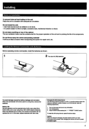
... the system for a long time, remove the batteries. When the batteries are run down, the remote commander will be sure to preset the stations again. To use the receiver where the frequency allocation system is based on a 9 kHz interval, make the following adjustments. 1 Turn on top of its components. After changing the interval, be erased. near heat sources such as shown. 1 2 Two...
... the system for a long time, remove the batteries. When the batteries are run down, the remote commander will be sure to preset the stations again. To use the receiver where the frequency allocation system is based on a 9 kHz interval, make the following adjustments. 1 Turn on top of its components. After changing the interval, be erased. near heat sources such as shown. 1 2 Two...
Operating Instructions
Page 6
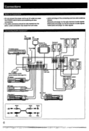
... an amplifier for video signals FM antenna • AM antenna Speaker system (A speakers) • Turntable system Fq el C=I =I 00 0 0000 O 0 00 • • - OUT DAT deck rn 0® 10 Tape deck 1 417Z"11.1.1 • oJ0 OUT 0 I OUT 1=1- Connecting Audio Equipment • Jacks and plugs of the connecting cord are color-coded as follows: Red jacks and plugs: for the right channel of audio signals White jacks and plugs: for the left channel of audio signals Yellow jacks and plugs: for center speakers Surround Speaker...
... an amplifier for video signals FM antenna • AM antenna Speaker system (A speakers) • Turntable system Fq el C=I =I 00 0 0000 O 0 00 • • - OUT DAT deck rn 0® 10 Tape deck 1 417Z"11.1.1 • oJ0 OUT 0 I OUT 1=1- Connecting Audio Equipment • Jacks and plugs of the connecting cord are color-coded as follows: Red jacks and plugs: for the right channel of audio signals White jacks and plugs: for the left channel of audio signals Yellow jacks and plugs: for center speakers Surround Speaker...
Operating Instructions
Page 9
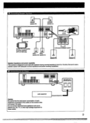
0 Connecting Speaker Systems Surrond speake (R) Surround speaker (L) m 0000 09 00000 O 0000009 L -J AIM 0 40- 40 40 4 AUDIO IN ;. 15 mm • A Es Morifor TV or an amplifier for center speakers (STR-AV1020 only) a DRLC DRLC speaker (R) speaker (L) to the second speaker system Speaker (R) Speaker (L Speaker Impedance and power capability This receiver is designed to work best with speakers having nominal impedance from 8 to 16 ohms. Be sure to use a speaker system with adequate nominal impedance and power handling capabilities...
0 Connecting Speaker Systems Surrond speake (R) Surround speaker (L) m 0000 09 00000 O 0000009 L -J AIM 0 40- 40 40 4 AUDIO IN ;. 15 mm • A Es Morifor TV or an amplifier for center speakers (STR-AV1020 only) a DRLC DRLC speaker (R) speaker (L) to the second speaker system Speaker (R) Speaker (L Speaker Impedance and power capability This receiver is designed to work best with speakers having nominal impedance from 8 to 16 ohms. Be sure to use a speaker system with adequate nominal impedance and power handling capabilities...

Operating Instructions
Page 10
... Identification Front Panel Amplifier and general section EDIT AUDIO button (STR-AV920) Remote control sensor DRLC POWER switch POWER switch EDIT buttons (STR-AV1020) MUTING switch and indicator i=k CI 0000 CIO 0 0000 VOLUME control © L--1 I I BALANCE control CURSOR MODE selectors and HEADPHONES jack operation buttons SPEAKERS selector VIDEO 3/INPUT jack (STR-AV1020 only) Function selectors and TAPE 2 MONITOR button and indicator Tuner section 0 1rM TUNING DIRECT button MEMORY button PGM SET (program set) button TUNER operation buttons Numeric buttons 00 fwl...
... Identification Front Panel Amplifier and general section EDIT AUDIO button (STR-AV920) Remote control sensor DRLC POWER switch POWER switch EDIT buttons (STR-AV1020) MUTING switch and indicator i=k CI 0000 CIO 0 0000 VOLUME control © L--1 I I BALANCE control CURSOR MODE selectors and HEADPHONES jack operation buttons SPEAKERS selector VIDEO 3/INPUT jack (STR-AV1020 only) Function selectors and TAPE 2 MONITOR button and indicator Tuner section 0 1rM TUNING DIRECT button MEMORY button PGM SET (program set) button TUNER operation buttons Numeric buttons 00 fwl...

Operating Instructions
Page 13
El Tuner section INDEX SELECT and INDEX +/- buttons: Select a preset station. LINK: Links sound field to 0) and ENTER buttons: Select the TV channel. LDP/VTR/TV/AUDIO POWER buttons: Control the power of the receiver. (The VIDEO 3 button does not operate on the STR-AV920.) DIGITAL button (RM-P301 only): This button does not operate. VOL (volume) + / - W Amplifier section FUNCTION selectors: Select an input source of each speaker. (This button does not operate on the STR-AV920.) EQUALIZER ON/OFF button: Turns on the VCR. 441/*W: fast winding 0: Stop 41...
El Tuner section INDEX SELECT and INDEX +/- buttons: Select a preset station. LINK: Links sound field to 0) and ENTER buttons: Select the TV channel. LDP/VTR/TV/AUDIO POWER buttons: Control the power of the receiver. (The VIDEO 3 button does not operate on the STR-AV920.) DIGITAL button (RM-P301 only): This button does not operate. VOL (volume) + / - W Amplifier section FUNCTION selectors: Select an input source of each speaker. (This button does not operate on the STR-AV920.) EQUALIZER ON/OFF button: Turns on the VCR. 441/*W: fast winding 0: Stop 41...
Operating Instructions
Page 14
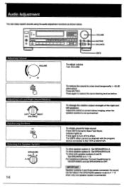
... output strength of the right and left speakers Adjust BALANCE to OFF. To obtain powerful bass sound Press DBFB (Dynamic Bass Feed Back). VOLUME MUTING BALANCE DBFB 10 -20dB Adjusting Left and Right Sound Balance r'N LEFT RIGHT BALANCE Reinforcing the Bass an Selecting the Speaker System SPEAKERS OFF A A+B 14 To reduce the sound to B. To drive speaker system B: Set SPEAKERS to a low level temporarily ( -20 dB attenuation) Press MUTING. No sound can enjoy superb sounds using the audio adjustment functions...
... output strength of the right and left speakers Adjust BALANCE to OFF. To obtain powerful bass sound Press DBFB (Dynamic Bass Feed Back). VOLUME MUTING BALANCE DBFB 10 -20dB Adjusting Left and Right Sound Balance r'N LEFT RIGHT BALANCE Reinforcing the Bass an Selecting the Speaker System SPEAKERS OFF A A+B 14 To reduce the sound to B. To drive speaker system B: Set SPEAKERS to a low level temporarily ( -20 dB attenuation) Press MUTING. No sound can enjoy superb sounds using the audio adjustment functions...
Operating Instructions
Page 15
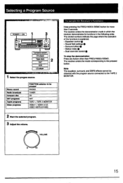
... selected program. 3 Adjust the volume. The circled numbers indicate the page where the operation of the functions is explained. - O 1O 15 Surround effect 0 - Sound field settings - The receiver enters the mode corresponding to the TAPE 2 MONITOR. VOLUME To sample the Receiver's Functions Keep pressing the FREQ/INDEX/DEMO button for more than FREQ/INDEX/DEMO. Equalizer control - Dual room link control To stop the demonstration Press any button other than 3 seconds. Phono record Radio broadcast Compact disc DAT programs Taped programs Video programs FUNCTION...
... selected program. 3 Adjust the volume. The circled numbers indicate the page where the operation of the functions is explained. - O 1O 15 Surround effect 0 - Sound field settings - The receiver enters the mode corresponding to the TAPE 2 MONITOR. VOLUME To sample the Receiver's Functions Keep pressing the FREQ/INDEX/DEMO button for more than FREQ/INDEX/DEMO. Equalizer control - Dual room link control To stop the demonstration Press any button other than 3 seconds. Phono record Radio broadcast Compact disc DAT programs Taped programs Video programs FUNCTION...
Operating Instructions
Page 20
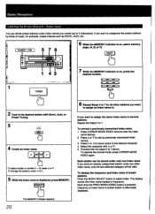
... indicator is on, press the desired number. 2 Tune in the desired station with Direct, Auto, or Preset Tuning. 3 • . ,• IN 4 Create an index name. To change the position, press or Radio Reception Labeling the Preset Stations - If you create (up to categorize the preset stations by kinds of music, for example, create indexes such as ROCK, JAZZ, etc. ; a v To select a letter or number (1 - 4), press A or...
... indicator is on, press the desired number. 2 Tune in the desired station with Direct, Auto, or Preset Tuning. 3 • . ,• IN 4 Create an index name. To change the position, press or Radio Reception Labeling the Preset Stations - If you create (up to categorize the preset stations by kinds of music, for example, create indexes such as ROCK, JAZZ, etc. ; a v To select a letter or number (1 - 4), press A or...
Operating Instructions
Page 21
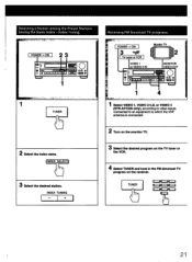
... name. TUNER 21 INDEX ELECT 3 Select the desired station. -INDEX TUNING + 1 1 Select VIDEO 1, VIDEO 2/LD, or VIDEO 3 (STR-AV1020 only), according to video inputs connected to an equipment to which the VHF antenna is connected. 2 Turn on the monitor TV. 3 Select the desired program on the TV tuner or the VCR. 4 Select TUNER and tune in the FM simulcast TV program on the receiver. Index Tuning .. MONITOR VIDEO OUT _ O Oa e =a ( 400) • 1 •;,•,::.i,..,,..z f . .';'". Selecting a Station among the Preset Stations having...
... name. TUNER 21 INDEX ELECT 3 Select the desired station. -INDEX TUNING + 1 1 Select VIDEO 1, VIDEO 2/LD, or VIDEO 3 (STR-AV1020 only), according to video inputs connected to an equipment to which the VHF antenna is connected. 2 Turn on the monitor TV. 3 Select the desired program on the TV tuner or the VCR. 4 Select TUNER and tune in the FM simulcast TV program on the receiver. Index Tuning .. MONITOR VIDEO OUT _ O Oa e =a ( 400) • 1 •;,•,::.i,..,,..z f . .';'". Selecting a Station among the Preset Stations having...

Operating Instructions
Page 22
... select the deck for playback. 4 Start the playback of the VOLUME, SURROUND, BALANCE, and graphic equalizer do not have connected a tape deck having separate record and playback heads to DAT IN TAPE 1 or 2 OUT DAT ON 5 WC 0 CIMIIIMIP-:. - 0 IMMIBI M EOW Neu 1. ---."-. To listen to the source sound again, press the button again. 22 Note on tape dubbing Tape dubbing is possible only in the recording mode. Monitoring...
... select the deck for playback. 4 Start the playback of the VOLUME, SURROUND, BALANCE, and graphic equalizer do not have connected a tape deck having separate record and playback heads to DAT IN TAPE 1 or 2 OUT DAT ON 5 WC 0 CIMIIIMIP-:. - 0 IMMIBI M EOW Neu 1. ---."-. To listen to the source sound again, press the button again. 22 Note on tape dubbing Tape dubbing is possible only in the recording mode. Monitoring...

Operating Instructions
Page 23
... STR-AV1020 With the STR-AV920 POWER ON TV tuner/VCR 2 I to VIDEO 2 1 VIDEO IN/ AUDIO IN 0 3 VCR 1 to VIDEO 1 (313aOa, VIDEO OUT/AUDIO OUT 1 Press EDIT VIDEO to select the playback-side VCR 2 I > 1: for VCR 3 2 Press VIDEO 2/LD or VIDEO 3 to select the video signal to monitor on the monitor TV. VIDEO 2/LD: for VCR 2 VIDEO 3: for VCR 3 3 Set the playback-side VCR to the recording mode. Press the appropriate FUNCTION selector. 2. Recording a TV program...
... STR-AV1020 With the STR-AV920 POWER ON TV tuner/VCR 2 I to VIDEO 2 1 VIDEO IN/ AUDIO IN 0 3 VCR 1 to VIDEO 1 (313aOa, VIDEO OUT/AUDIO OUT 1 Press EDIT VIDEO to select the playback-side VCR 2 I > 1: for VCR 3 2 Press VIDEO 2/LD or VIDEO 3 to select the video signal to monitor on the monitor TV. VIDEO 2/LD: for VCR 2 VIDEO 3: for VCR 3 3 Set the playback-side VCR to the recording mode. Press the appropriate FUNCTION selector. 2. Recording a TV program...

Operating Instructions
Page 27
Placement of Speakers for a center speaker. PHANTOM mode When connecting only front and rear speakers. 3CH mode When connecting front speakers and a center speaker. Center off mode (when no indicator of DOLBY PRO LOGIC mode lights up.) Set the receiver to this mode when adjusting INPUT BALANCE to obtain the best Dolby surround effect with the program source connected to the TAPE 2 MONITOR. Note The amount of speaker as movie theaters and gives a theater-like listening it in a concert hall. Obtaining the Surround Effect Available Types of...
Placement of Speakers for a center speaker. PHANTOM mode When connecting only front and rear speakers. 3CH mode When connecting front speakers and a center speaker. Center off mode (when no indicator of DOLBY PRO LOGIC mode lights up.) Set the receiver to this mode when adjusting INPUT BALANCE to obtain the best Dolby surround effect with the program source connected to the TAPE 2 MONITOR. Note The amount of speaker as movie theaters and gives a theater-like listening it in a concert hall. Obtaining the Surround Effect Available Types of...
Operating Instructions
Page 28
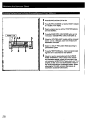
.... 4 Press the DOLBY PRO LOGIC MODE button so that no indicator of DOLBY PRO LOGIC mode lights up. 5 Adjust the INPUT BALANCE control until the monaural sound, such as a TV or amplifier, so that sound from each speaker is heard in succession to each speaker. 8 Adjust the level of rear speakers with controller of the unit connected to your speaker system. 7 Press the TEST TONE button. Obtaining the Surround Effect Adjusting the Input Level for Dolby Surround System (STR-AV1020 only) POWER ON r1 E ms...
.... 4 Press the DOLBY PRO LOGIC MODE button so that no indicator of DOLBY PRO LOGIC mode lights up. 5 Adjust the INPUT BALANCE control until the monaural sound, such as a TV or amplifier, so that sound from each speaker is heard in succession to each speaker. 8 Adjust the level of rear speakers with controller of the unit connected to your speaker system. 7 Press the TEST TONE button. Obtaining the Surround Effect Adjusting the Input Level for Dolby Surround System (STR-AV1020 only) POWER ON r1 E ms...

Operating Instructions
Page 32
...; • • Rear o the receiver I 4 or amplifier • • • • mimmos ELN EN S • + - + DAL C SPE AKE • "Ausimmo0 I Second room Extension cable RK-C2020 Speaker (L) Speaker (R) I i • DRLC receiver RMR-2020 Speaker cords • 32 Enjoying Sound in the second room. When the RM-S2020K Dual Room Link Control Kit (optional) and optional speakers are properly connected to your audio system and...
...; • • Rear o the receiver I 4 or amplifier • • • • mimmos ELN EN S • + - + DAL C SPE AKE • "Ausimmo0 I Second room Extension cable RK-C2020 Speaker (L) Speaker (R) I i • DRLC receiver RMR-2020 Speaker cords • 32 Enjoying Sound in the second room. When the RM-S2020K Dual Room Link Control Kit (optional) and optional speakers are properly connected to your audio system and...
Operating Instructions
Page 34
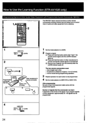
... "learn It depends on the format of the signal. If you to control most of audio and video equipment from the button(s) after the LEARN indicator goes off. How to Use the Learning Function (STR-AV1020 only) Programming Signals of Other Audio/Video Equipment with the programmed signals. The two remote commanders must: • face straight each button to be programmed. 4 Set the mode selector to USER STD or SONY STD.
... "learn It depends on the format of the signal. If you to control most of audio and video equipment from the button(s) after the LEARN indicator goes off. How to Use the Learning Function (STR-AV1020 only) Programming Signals of Other Audio/Video Equipment with the programmed signals. The two remote commanders must: • face straight each button to be programmed. 4 Set the mode selector to USER STD or SONY STD.

Operating Instructions
Page 36
... EQUALIZER ON/OFF. Should any problem persist after you have been preset. The commander head is in by AutoTuning operation. The STEREO indicator flickers or does not appear when receiving stereo programs. No station can be located by Auto-Tuning operation. Change the tuning interval according to MONO mode. Surround Function Problem Surround effect cannot be adjusted. Adjust the antenna or connect an external FM antenna. Surround circuit is turned off . Press the FM MODE button to set incorrectly. Troubleshooting Guide...
... EQUALIZER ON/OFF. Should any problem persist after you have been preset. The commander head is in by AutoTuning operation. The STEREO indicator flickers or does not appear when receiving stereo programs. No station can be located by Auto-Tuning operation. Change the tuning interval according to MONO mode. Surround Function Problem Surround effect cannot be adjusted. Adjust the antenna or connect an external FM antenna. Surround circuit is turned off . Press the FM MODE button to set incorrectly. Troubleshooting Guide...
Operating Instructions
Page 37
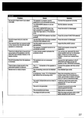
... a TV set correctly. Turn off the unit, eliminate the shortcircuit problem and turn on the power again. Use shielded type cords. The TAPE 2 MONITOR button has been pressed for a program source other than tape deck 2. (The indicator is reversed. A short-circuit problem activates the protective circuit. The +/ - Press the button to the antenna ground terminal. Adjust the BALANCE control. If there is heard only at a very low volume. Place the connecting cords in the display window...
... a TV set correctly. Turn off the unit, eliminate the shortcircuit problem and turn on the power again. Use shielded type cords. The TAPE 2 MONITOR button has been pressed for a program source other than tape deck 2. (The indicator is reversed. A short-circuit problem activates the protective circuit. The +/ - Press the button to the antenna ground terminal. Adjust the BALANCE control. If there is heard only at a very low volume. Place the connecting cords in the display window...


