Service Manual
Page 1
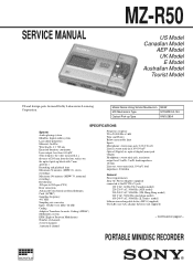
...supplied) - PORTABLE MINIDISC RECORDER MICROFILM SERVICE MANUAL MZ-R50 US Model Canadian Model AEP Model UK Model E Model Australian Model Tourist Model US and foreign parts licensed Dolby Laboratories Licensing Corporation. Model Name Using Similar Machanism MD Machanism Type Optical Pick-up block with 7 mm aperture.) Recording..., load impedance 16 ohm Line out: stereo mini-jack, 194 mV, load impedance 10 kilohm General Power requirements Sony AC Power Adaptor (supplied) connected at a distance of channels 2 stereo channels 1 monaural channel Frequency response 20 to Fourteen Modulation...
...supplied) - PORTABLE MINIDISC RECORDER MICROFILM SERVICE MANUAL MZ-R50 US Model Canadian Model AEP Model UK Model E Model Australian Model Tourist Model US and foreign parts licensed Dolby Laboratories Licensing Corporation. Model Name Using Similar Machanism MD Machanism Type Optical Pick-up block with 7 mm aperture.) Recording..., load impedance 16 ohm Line out: stereo mini-jack, 194 mV, load impedance 10 kilohm General Power requirements Sony AC Power Adaptor (supplied) connected at a distance of channels 2 stereo channels 1 monaural channel Frequency response 20 to Fourteen Modulation...
Service Manual
Page 2
... SUPPLÉMENTS PUBLIÉS PAR SONY. - 2 - Upper Panel Assy, Bottom Panel Assy Removal ...... 20 3-2. ATTENTION AU COMPOSANT AYANT RAPPORT À LA SÉCURITÉ! For customers in .) Mass Approx. 190 g (6.8 oz) the recorder only Approx. 240 g (8.5 oz) incl, a recordable MD, and LIP-8 lithium ion rechargeable battery Supplied accessories AC power adaptor (1) Headphones with JOG Dial...
... SUPPLÉMENTS PUBLIÉS PAR SONY. - 2 - Upper Panel Assy, Bottom Panel Assy Removal ...... 20 3-2. ATTENTION AU COMPOSANT AYANT RAPPORT À LA SÉCURITÉ! For customers in .) Mass Approx. 190 g (6.8 oz) the recorder only Approx. 240 g (8.5 oz) incl, a recordable MD, and LIP-8 lithium ion rechargeable battery Supplied accessories AC power adaptor (1) Headphones with JOG Dial...
Service Manual
Page 25
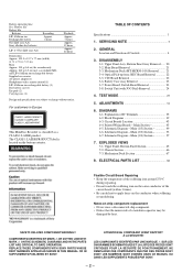
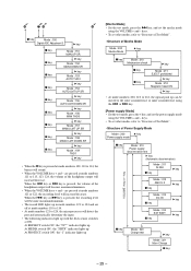
... 00 Dot Section : POWER General Adjustment Mode Segment Section : 4000 Dot Section : Assy MODE • In modes other than the general adjustment mode, the last two digits of the mode number will display as follows. ROM version displayed / all lit / all off the power supply and open the soldering ...bridge of TAP803 (TEST) on the power supply. [MAIN BOARD] (SIDE B) C315 26 TAP803 (TEST) 25 [Operations When Test Mode is Set] When the test...
... 00 Dot Section : POWER General Adjustment Mode Segment Section : 4000 Dot Section : Assy MODE • In modes other than the general adjustment mode, the last two digits of the mode number will display as follows. ROM version displayed / all lit / all off the power supply and open the soldering ...bridge of TAP803 (TEST) on the power supply. [MAIN BOARD] (SIDE B) C315 26 TAP803 (TEST) 25 [Operations When Test Mode is Set] When the test...
Service Manual
Page 29
...with the deck sensor switches at ON. keys. • To set other modes, refer to 113, 123, 124, the volume of Power Supply Mode Mode : 300 " key Power supply mode p key MM ode : 310 Power supply discrimination test " key (Automatic discrimination) Mode : 311 Ni MH p key " key VOLUME +key or - 6 78 9 p key... To set other modes, refer to "Structure of Test Mode". • Structure of the headphone output will become maximum/minimum. • The record LED lights up in mode numbers 121 to 124 and are pressed at mode numbers 111 to "Structure of Test Mode". • Structure of ...
...with the deck sensor switches at ON. keys. • To set other modes, refer to 113, 123, 124, the volume of Power Supply Mode Mode : 300 " key Power supply mode p key MM ode : 310 Power supply discrimination test " key (Automatic discrimination) Mode : 311 Ni MH p key " key VOLUME +key or - 6 78 9 p key... To set other modes, refer to "Structure of Test Mode". • Structure of the headphone output will become maximum/minimum. • The record LED lights up in mode numbers 121 to 124 and are pressed at mode numbers 111 to "Structure of Test Mode". • Structure of ...
Service Manual
Page 31
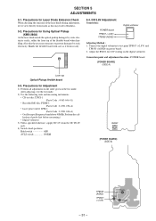
...the following tools and measuring instruments. • CD test disc TDYS-1 (Parts Code : 4-963-646-01) • Recorded MO disc PTDM-1 (Parts Code : J-2501-054-A) • Laser power meter LPM-1 (Parts Code : J-2501-046-A) • Oscilloscope (Frequency band above 40MHz. Perform the calibration of the ... laser tap of probe first before measuring.) • Digital voltmeter 3) Unless specified othewise, supply DC 6V from the DC IN 6V jack. 4) Swtich, knob positions Hold switch OFF AVLS switch NORM RV801 [POWER BOARD] (SIDE B) TP8505 (AGND) TP8507 (+2.8V) TP8505 TP8507 TP8503 - 31 - ...
...the following tools and measuring instruments. • CD test disc TDYS-1 (Parts Code : 4-963-646-01) • Recorded MO disc PTDM-1 (Parts Code : J-2501-054-A) • Laser power meter LPM-1 (Parts Code : J-2501-046-A) • Oscilloscope (Frequency band above 40MHz. Perform the calibration of the ... laser tap of probe first before measuring.) • Digital voltmeter 3) Unless specified othewise, supply DC 6V from the DC IN 6V jack. 4) Swtich, knob positions Hold switch OFF AVLS switch NORM RV801 [POWER BOARD] (SIDE B) TP8505 (AGND) TP8507 (+2.8V) TP8505 TP8507 TP8503 - 31 - ...
Service Manual
Page 35
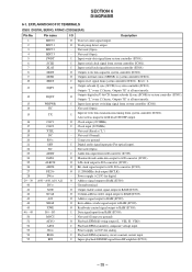
...subcode Q sync (SCOR) to D/A converter (IC303). I Inputs write data signal from system controller (IC801). Connect to system controller (IC801). Power supply (+2.8V) for digital. Not used (Ground). - I Input of write data taransmission timing from system controller (IC801). Outputs "H" at "L") -...EFM asymmetry comparate voltage input. - O Output enable contol signal output to system controller (IC801). Not used (Connect to ground). Power supply (+2.8V) for analog. Not used (Fixed at all most mostly. I Inputs reset signal from RF amplifier (IC501). - ...
...subcode Q sync (SCOR) to D/A converter (IC303). I Inputs write data signal from system controller (IC801). Connect to system controller (IC801). Power supply (+2.8V) for digital. Not used (Ground). - I Input of write data taransmission timing from system controller (IC801). Outputs "H" at "L") -...EFM asymmetry comparate voltage input. - O Output enable contol signal output to system controller (IC801). Not used (Connect to ground). Power supply (+2.8V) for analog. Not used (Fixed at all most mostly. I Inputs reset signal from RF amplifier (IC501). - ...
Service Manual
Page 36
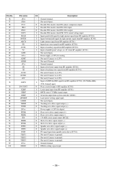
...I Input focus error signal from RF amplifier (IC501). I FG signal input from RF amplifier (IC501). - Power supply (+2.8V) for analog. - I Laser power setting signal input. - I Decoder PLL master clock PLL VCO control voltage input. O Sled servo drive signal... O Decoder PLL master clock PLL filter output. Power supply (+2.8V) for digital. O Tracking servo drive signal output (-). Not used (Open). I Serial data input from RF amplifier (IC501). O Spindle servo drive signal output (+). O EFM recording signal ouput. - 36 - I Latch signal...
...I Input focus error signal from RF amplifier (IC501). I FG signal input from RF amplifier (IC501). - Power supply (+2.8V) for analog. - I Laser power setting signal input. - I Decoder PLL master clock PLL VCO control voltage input. O Sled servo drive signal... O Decoder PLL master clock PLL filter output. Power supply (+2.8V) for digital. O Tracking servo drive signal output (-). Not used (Open). I Serial data input from RF amplifier (IC501). O Spindle servo drive signal output (+). O EFM recording signal ouput. - 36 - I Latch signal...
Service Manual
Page 38
... output. I JOG dial signal input. H : BEEP sound output I This is at "L") - O D/A converter power down O O Stepping motor control signal output. H : Power down detect during recording. H : Charge - 38 - I Subcode Q sync (SCOR) of digital in U-bit CD format from motor ... SCK2 ------- I CD/MO discrimination switch. - I Chip select input. O BEEP sound output control. I Key input. Power supply pin (+2.8V). - A/D converter power supply terminal. I UNREG voltage monitor. I Key input. I Temp meter (IC803) input. L : EXT battery I Input ...
... output. I JOG dial signal input. H : BEEP sound output I This is at "L") - O D/A converter power down O O Stepping motor control signal output. H : Power down detect during recording. H : Charge - 38 - I Subcode Q sync (SCOR) of digital in U-bit CD format from motor ... SCK2 ------- I CD/MO discrimination switch. - I Chip select input. O BEEP sound output control. I Key input. Power supply pin (+2.8V). - A/D converter power supply terminal. I UNREG voltage monitor. I Key input. I Temp meter (IC803) input. L : EXT battery I Input ...
Service Manual
Page 40
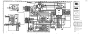
...;curité. tion tolerances. • Waveforms are in µF unless otherwise noted. Voltage variations may be noted due to normal produc- MZ-R50 sont cri- line with part une piéce portant le number specified. tical for IC Block Diagram. - 49 - - 50 -... - or dotted par une marque ! numéro spécifié. • A : B+ Line. • Power voltage is dc 6V and fed with regulated dc power supply from external power voltage jack (J901). • Voltages and waveforms are taken with respect to waveforms. • Signal path. no mark : ...
...;curité. tion tolerances. • Waveforms are in µF unless otherwise noted. Voltage variations may be noted due to normal produc- MZ-R50 sont cri- line with part une piéce portant le number specified. tical for IC Block Diagram. - 49 - - 50 -... - or dotted par une marque ! numéro spécifié. • A : B+ Line. • Power voltage is dc 6V and fed with regulated dc power supply from external power voltage jack (J901). • Voltages and waveforms are taken with respect to waveforms. • Signal path. no mark : ...
Service Manual
Page 41
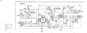
... - 53 - - 54 - - 55 - - 56 - MZ-R50 6-6. pF: µµF 50 WV or less are not indicated except for IC Block Diagrams. Note: • All capacitors are in Ω and 1/4 W or less unless otherwise specified. • A : B+ Line. • Power voltage is dc 6V and fed with regulated dc power supply from external power voltage jack (J901). •...
... - 53 - - 54 - - 55 - - 56 - MZ-R50 6-6. pF: µµF 50 WV or less are not indicated except for IC Block Diagrams. Note: • All capacitors are in Ω and 1/4 W or less unless otherwise specified. • A : B+ Line. • Power voltage is dc 6V and fed with regulated dc power supply from external power voltage jack (J901). •...
Service Manual
Page 42
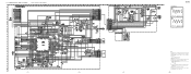
...¢ : internal component. • A : B+ Line. • C : panel designation. • Power voltage is dc 6V and fed with regulated dc power supply from external power voltage jack (J901). • Voltages and waveforms are dc with respect to normal produc- no -signal conditions.... Voltage variations may be noted due to waveforms. - 60 - tion tolerances. • Circled numbers refer to normal produc- MZ-R50 ...
...¢ : internal component. • A : B+ Line. • C : panel designation. • Power voltage is dc 6V and fed with regulated dc power supply from external power voltage jack (J901). • Voltages and waveforms are dc with respect to normal produc- no -signal conditions.... Voltage variations may be noted due to waveforms. - 60 - tion tolerances. • Circled numbers refer to normal produc- MZ-R50 ...


