Service Manual
Page 1
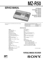
PORTABLE MINIDISC RECORDER MICROFILM SERVICE MANUAL MZ-R50 US Model Canadian Model AEP Model UK Model E Model Australian Model Tourist Model US and foreign parts licensed Dolby Laboratories Licensing Corporation. Continued on the optical pick-up Type NEW MT-MZR-50-143 KMS-280A SPECIFICATIONS System Audio playing system MiniDisc digital audio system Laser diode properties Material: GaAIAs Wavelength: λ = 780 nm Emission duration: continuous Laser output: less than 44.6 µW (This output is the...
PORTABLE MINIDISC RECORDER MICROFILM SERVICE MANUAL MZ-R50 US Model Canadian Model AEP Model UK Model E Model Australian Model Tourist Model US and foreign parts licensed Dolby Laboratories Licensing Corporation. Continued on the optical pick-up Type NEW MT-MZR-50-143 KMS-280A SPECIFICATIONS System Audio playing system MiniDisc digital audio system Laser diode properties Material: GaAIAs Wavelength: λ = 780 nm Emission duration: continuous Laser output: less than 44.6 µW (This output is the...
Service Manual
Page 2
... MODE 25 5. Main (1/3) Section 49 6-6. Schematic Diagram - REPLACE THESE COMPONENTS WITH SONY PARTS WHOSE PART NUMBERS APPEAR AS SHOWN IN THIS MANUAL OR IN SUPPLEMENTS PUBLISHED BY SONY. For customers in .) Mass Approx. 190 g (6.8 oz) the recorder only Approx. 240 g (8.5 oz) incl, a recordable MD, and LIP-8 lithium ion rechargeable battery Supplied accessories AC power adaptor (1) Headphones with JOG Dial) Removal 24 4. GENERAL Location and Function...
... MODE 25 5. Main (1/3) Section 49 6-6. Schematic Diagram - REPLACE THESE COMPONENTS WITH SONY PARTS WHOSE PART NUMBERS APPEAR AS SHOWN IN THIS MANUAL OR IN SUPPLEMENTS PUBLISHED BY SONY. For customers in .) Mass Approx. 190 g (6.8 oz) the recorder only Approx. 240 g (8.5 oz) incl, a recordable MD, and LIP-8 lithium ion rechargeable battery Supplied accessories AC power adaptor (1) Headphones with JOG Dial) Removal 24 4. GENERAL Location and Function...
Service Manual
Page 25
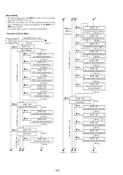
... : AUDIO Mecha Mode Segment Section : 00 00 Dot Section : MECHA Select dial number (blinks) Power Mode Segment Section : 00 Dot Section : POWER General Adjustment Mode Segment Section : 4000 Dot Section : Assy MODE • In modes other than the general adjustment mode, the last two digits of the following repeatedly. key IC801 1 100 TAP803 (Test mode) Short : Test mode Open : Normal mode [Exiting the Test Mode] Turn off • The display...
... : AUDIO Mecha Mode Segment Section : 00 00 Dot Section : MECHA Select dial number (blinks) Power Mode Segment Section : 00 Dot Section : POWER General Adjustment Mode Segment Section : 4000 Dot Section : Assy MODE • In modes other than the general adjustment mode, the last two digits of the following repeatedly. key IC801 1 100 TAP803 (Test mode) Short : Test mode Open : Normal mode [Exiting the Test Mode] Turn off • The display...
Service Manual
Page 26
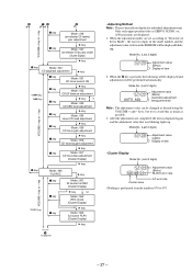
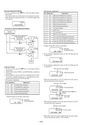
... CD level adjustment *2 " key Mode : 036 Laser MO reM ad adjustment " key Mode : 037 MO focus gMain adjustment " key Mode : 038 MO tracking Mgain adjustment " key Mode : 039 MO focusM bias variable (Cluster Display) " key p key Low reM fleMcotidoen : 040 CD playback adjustment " key p key p key p key Mode : 041 Low reflection CM D focus serch ON " key Mode : 042 Low reflection CD EF balance adjustment " key *1 Mode : 043 Low reflection CD ABCD level adjustment VOLUME...
... CD level adjustment *2 " key Mode : 036 Laser MO reM ad adjustment " key Mode : 037 MO focus gMain adjustment " key Mode : 038 MO tracking Mgain adjustment " key Mode : 039 MO focusM bias variable (Cluster Display) " key p key Low reM fleMcotidoen : 040 CD playback adjustment " key p key p key p key Mode : 041 Low reflection CM D focus serch ON " key Mode : 042 Low reflection CD EF balance adjustment " key *1 Mode : 043 Low reflection CD ABCD level adjustment VOLUME...
Service Manual
Page 27
... EF balance adjustment " key *1 Mode : 053 CD ABC level adjustment VOLUME +key or - Mode No. (Last 2 digits) 52 09 Adjustment value (Blinks) Display of item • Cluster Display Mode No. (Last 2 digits) 52 09 026 4B 01 Adjustment value (Blinks) BLOCK error rate Cluster value AT error rate • Nothing is pressed, the following will be displayed and adjustments will be changed as desired using the VOLUME + and - key p key " key Mode : 054...
... EF balance adjustment " key *1 Mode : 053 CD ABC level adjustment VOLUME +key or - Mode No. (Last 2 digits) 52 09 Adjustment value (Blinks) Display of item • Cluster Display Mode No. (Last 2 digits) 52 09 026 4B 01 Adjustment value (Blinks) BLOCK error rate Cluster value AT error rate • Nothing is pressed, the following will be displayed and adjustments will be changed as desired using the VOLUME + and - key p key " key Mode : 054...
Service Manual
Page 28
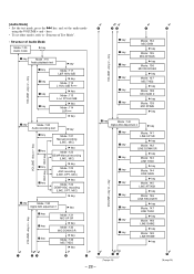
... Mode : 121 Manual recording (LINE, MIC) p key " key Mode : 122 DEMP Manual recording (LINE, MIC) p key " key Mode : 123 AGC recording (LINE, OPT, MIC) p key " key Mode : 124 DEMP AGC recording (LINE, OPT, MIC) " key p key DigitaM l Mode : 130 AGC adjustment 1 " key VOLUME +key or - [Audio Mode] • Set the test mode, press the + key, and set other modes, refer to "Structure of Test Mode". • Structuer of Audio Mode Mode : 100 Audio mode " key p key MM ode : 110 Audio playback...
... Mode : 121 Manual recording (LINE, MIC) p key " key Mode : 122 DEMP Manual recording (LINE, MIC) p key " key Mode : 123 AGC recording (LINE, OPT, MIC) p key " key Mode : 124 DEMP AGC recording (LINE, OPT, MIC) " key p key DigitaM l Mode : 130 AGC adjustment 1 " key VOLUME +key or - [Audio Mode] • Set the test mode, press the + key, and set other modes, refer to "Structure of Test Mode". • Structuer of Audio Mode Mode : 100 Audio mode " key p key MM ode : 110 Audio playback...
Service Manual
Page 29
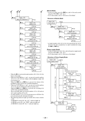
... and automatically determine the input. • The following indicators light up with the deck sensor switches at mode numbers 111 to 113, 123, 124, the volume of the headphone output will increase/decrease. When the = key or + key is pressed, the recording level will become maximum/minimum. • When the VOLUME keys + and - key Mode : 312 AM3 ! 2 p key " key Mode : 313 DC IN...
... and automatically determine the input. • The following indicators light up with the deck sensor switches at mode numbers 111 to 113, 123, 124, the volume of the headphone output will increase/decrease. When the = key or + key is pressed, the recording level will become maximum/minimum. • When the VOLUME keys + and - key Mode : 312 AM3 ! 2 p key " key Mode : 313 DC IN...
Service Manual
Page 30
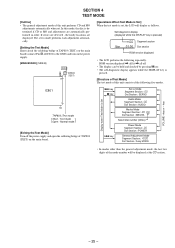
... displayed. Mode No. (Last 2 digits) 39 03 CD mode NG AT error value * When NG, set the general adjust- ment mode. 2. Adjustment 1 032 MO playback EF balance adjustment 2 033 MO playback ABCD level adjustment 3 034 MO recording EF balance adjustment 4 035 MO recording ABCD level adjustment 5 037 MO focus gain adjustment 6 038 MO tracking gain adjustment 7 061 32 cluster full REC 8 062 REC shock 9 063 32 cluster PLAY 10 039 MO focus bias adjustment 11 042 Low...
... displayed. Mode No. (Last 2 digits) 39 03 CD mode NG AT error value * When NG, set the general adjust- ment mode. 2. Adjustment 1 032 MO playback EF balance adjustment 2 033 MO playback ABCD level adjustment 3 034 MO recording EF balance adjustment 4 035 MO recording ABCD level adjustment 5 037 MO focus gain adjustment 6 038 MO tracking gain adjustment 7 061 32 cluster full REC 8 062 REC shock 9 063 32 cluster PLAY 10 039 MO focus bias adjustment 11 042 Low...
Service Manual
Page 31
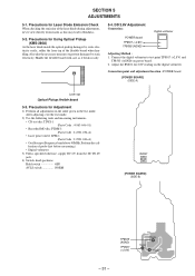
... power board. 2. Connect the digital voltmeter to blindness. 5-2. After adjusting, exit the test mode. 2) Use the following tools and measuring instruments. • CD test disc TDYS-1 (Parts Code : 4-963-646-01) • Recorded MO disc PTDM-1 (Parts Code : J-2501-054-A) • Laser power meter LPM-1 (Parts Code : J-2501-046-A) • Oscilloscope (Frequency band above 40MHz. SECTION 5 ADJUSTMENTS 5-1. Perform the calibration of the laser diode during adjustments, never view directly...
... power board. 2. Connect the digital voltmeter to blindness. 5-2. After adjusting, exit the test mode. 2) Use the following tools and measuring instruments. • CD test disc TDYS-1 (Parts Code : 4-963-646-01) • Recorded MO disc PTDM-1 (Parts Code : J-2501-054-A) • Laser power meter LPM-1 (Parts Code : J-2501-046-A) • Oscilloscope (Frequency band above 40MHz. SECTION 5 ADJUSTMENTS 5-1. Perform the calibration of the laser diode during adjustments, never view directly...
Service Manual
Page 32
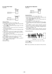
.... (Traverse Waveform) A 0V C B Specification : A = B, C >= 1.0 Vp-p 9. Laser Power Check Connection : Laser power meter Optical pickup objective lens MAIN board AP5117 (VCC) AP574 (LDIO) Digital voltmeter Adjusting Method : 1. Open the cover and set the MO recording EF balance adjustment mode (Mode : 034). 8. Slide the recording key and set the laser power meter on the market. 5. Press the " key, and set the laser power adjustment mode (Mode : 020) using the volume + and - keys. 3. Press...
.... (Traverse Waveform) A 0V C B Specification : A = B, C >= 1.0 Vp-p 9. Laser Power Check Connection : Laser power meter Optical pickup objective lens MAIN board AP5117 (VCC) AP574 (LDIO) Digital voltmeter Adjusting Method : 1. Open the cover and set the MO recording EF balance adjustment mode (Mode : 034). 8. Slide the recording key and set the laser power meter on the market. 5. Press the " key, and set the laser power adjustment mode (Mode : 020) using the volume + and - keys. 3. Press...
Service Manual
Page 33
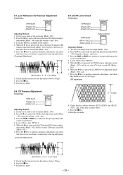
... P key to perform automatic adjustment, and check that the RF level is pressed, the low reflection CD playback EF balance adjustment mode (Mode : 042) will be set after CD focus search ON (Mode : 051). 6. ment mode (Mode : 052) will be set after low reflection CD focus search ON (Mode : 041). 5. A 0V C B Specification : A = B, C >= 1.0 Vp-p 7. Press the " key, and set the CD playback adjustment mode (Mode : 050) using the volume + and -keys. 3. When the...
... P key to perform automatic adjustment, and check that the RF level is pressed, the low reflection CD playback EF balance adjustment mode (Mode : 042) will be set after CD focus search ON (Mode : 051). 6. ment mode (Mode : 052) will be set after low reflection CD focus search ON (Mode : 041). 5. A 0V C B Specification : A = B, C >= 1.0 Vp-p 7. Press the " key, and set the CD playback adjustment mode (Mode : 050) using the volume + and -keys. 3. When the...
Service Manual
Page 35
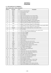
...system controller (IC801). Not used (Open). - I Digital audio signal input pin (For optical input). - D3 MVCI ASYO ASYI AVDD BIAS RFI O Traverse count signal output. I Clock input (22.5MHz). - I Inputs serial clock signal from system controller (IC801). I Data signal input from system controller (IC801). - I Inputs laser power switching signal from RAM (IC509). - O Clock output (22.5MHz). SECTION 6 DIAGRAMS 6-1. EXPLANATION OF IC TERMINALS IC503 DIGITAL SERVO, ATRAC (CXD2652AR) Pin No. O Track jump detect output. - Not used (Open). I Playback EFM asymmetry...
...system controller (IC801). Not used (Open). - I Digital audio signal input pin (For optical input). - D3 MVCI ASYO ASYI AVDD BIAS RFI O Traverse count signal output. I Clock input (22.5MHz). - I Inputs serial clock signal from system controller (IC801). I Data signal input from system controller (IC801). - I Inputs laser power switching signal from RAM (IC509). - O Clock output (22.5MHz). SECTION 6 DIAGRAMS 6-1. EXPLANATION OF IC TERMINALS IC503 DIGITAL SERVO, ATRAC (CXD2652AR) Pin No. O Track jump detect output. - Not used (Open). I Playback EFM asymmetry...
Service Manual
Page 36
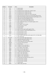
... used (Open). Power supply (+2.8V) for digital. Ground terminal. O Tracking servo drive signal output (+). - O Spindle servo drive signal output (-). Ground terminal. I Inputs bottom hold signal for light amount signal from RF amplifier (IC501). I Input of auxiliary signal from RF amplifier (IC501). - I Input of tracking error signal from RF amplifier (IC501). I Serial data input from RF amplifier (IC501) (22.05kHz±1kHz). (TTL Schmidt input) O Focus control output to +2.8V). - Not used (Open). O 176.4kHz clock signal output...
... used (Open). Power supply (+2.8V) for digital. Ground terminal. O Tracking servo drive signal output (+). - O Spindle servo drive signal output (-). Ground terminal. I Inputs bottom hold signal for light amount signal from RF amplifier (IC501). I Input of auxiliary signal from RF amplifier (IC501). - I Input of tracking error signal from RF amplifier (IC501). I Serial data input from RF amplifier (IC501) (22.05kHz±1kHz). (TTL Schmidt input) O Focus control output to +2.8V). - Not used (Open). O 176.4kHz clock signal output...
Service Manual
Page 37
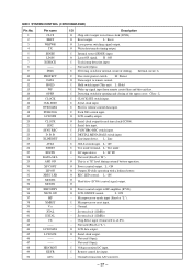
... O Chip select output to +2.8V). - I AVLS switch input. L : Line I Serial data input. O O Power control output to remote control. L : ON - O LCD data output. Not used (Open). B. I CLOCK SET switch input. Close : L I Hold switch input (This unit). I Microprocessor reset input. - O Power control output. L : ON O Head drive (IC506) control signal output. Microprocessor mode input (Fixed at "H" level during external battery operation. I Electric volume control data input. Not used (Open). - O Laser ON signal. H : Protect O Data output to RF...
... O Chip select output to +2.8V). - I AVLS switch input. L : Line I Serial data input. O O Power control output to remote control. L : ON - O LCD data output. Not used (Open). B. I CLOCK SET switch input. Close : L I Hold switch input (This unit). I Microprocessor reset input. - O Power control output. L : ON O Head drive (IC506) control signal output. Microprocessor mode input (Fixed at "H" level during external battery operation. I Electric volume control data input. Not used (Open). - O Laser ON signal. H : Protect O Data output to RF...
Service Manual
Page 38
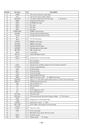
.... I AC adaptor or EXT battery detection input. I FG input from IC503. I Voltage monitor for an optical input. I Detecting input an optical input. I MEDIA switch input. O O Stepping motor control signal output. - H : BEEP sound output I This is at "L") - Not used : open) O Serial data output. O O Chip select output. O HF module control output. (Not used (Open). - I JOG dial signal input. I I PLAY/REC key input. I Subcode Q sync (SCOR) of digital in U-bit CD format from motor driver (IC701). I Input jack detection input. Power supply pin (+2.8V...
.... I AC adaptor or EXT battery detection input. I FG input from IC503. I Voltage monitor for an optical input. I Detecting input an optical input. I MEDIA switch input. O O Stepping motor control signal output. - H : BEEP sound output I This is at "L") - Not used : open) O Serial data output. O O Chip select output. O HF module control output. (Not used (Open). - I JOG dial signal input. I I PLAY/REC key input. I Subcode Q sync (SCOR) of digital in U-bit CD format from motor driver (IC701). I Input jack detection input. Power supply pin (+2.8V...
Service Manual
Page 40
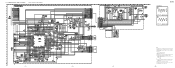
...power supply from external power voltage jack (J901). • Voltages and waveforms are taken with respect to ground under no mark : PB ( ) : REC • Voltages are cri- tion tolerances. • Waveforms are dc with a oscilloscope. E : PB a : REC - 52 - line with part une piéce portant le number...or less are not indicated except for safety. Note: Note: The components identi- are taken with a VOM (Input impedance 10 MΩ). MZ-R50 Les composants identifiés fied by mark ! tiques pour la sécurité. no -signal (detuned) conditions. ...
...power supply from external power voltage jack (J901). • Voltages and waveforms are taken with respect to ground under no mark : PB ( ) : REC • Voltages are cri- tion tolerances. • Waveforms are dc with a oscilloscope. E : PB a : REC - 52 - line with part une piéce portant le number...or less are not indicated except for safety. Note: Note: The components identi- are taken with a VOM (Input impedance 10 MΩ). MZ-R50 Les composants identifiés fied by mark ! tiques pour la sécurité. no -signal (detuned) conditions. ...
Service Manual
Page 41
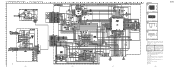
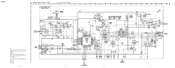
... dc power supply from external power voltage jack (J901). • Voltages and waveforms are taken with respect to normal produc- tion tolerances. • Signal path. MAIN (2/3) SECTION - Voltage variations may be noted due to ground under no mark : PB ( ) : REC • Voltages are dc with a VOM (Input impedance 10 MΩ). E : PB a : REC N : MIC - 53 - - 54 - - 55 - - 56 - no -signal conditions...
... dc power supply from external power voltage jack (J901). • Voltages and waveforms are taken with respect to normal produc- tion tolerances. • Signal path. MAIN (2/3) SECTION - Voltage variations may be noted due to ground under no mark : PB ( ) : REC • Voltages are dc with a VOM (Input impedance 10 MΩ). E : PB a : REC N : MIC - 53 - - 54 - - 55 - - 56 - no -signal conditions...
Service Manual
Page 42
... mark : PB ( ) : REC • Voltages are in Ω and 1/4 W or less unless otherwise specified. • ¢ : internal component. • A : B+ Line. • C : panel designation. • Power voltage is dc 6V and fed with regulated dc power supply from external power voltage jack (J901). • Voltages and waveforms are taken with a VOM (Input impedance 10 MΩ). MZ-R50 r WAVEFORMS 5 2.3Vp-p 12MHz...
... mark : PB ( ) : REC • Voltages are in Ω and 1/4 W or less unless otherwise specified. • ¢ : internal component. • A : B+ Line. • C : panel designation. • Power voltage is dc 6V and fed with regulated dc power supply from external power voltage jack (J901). • Voltages and waveforms are taken with a VOM (Input impedance 10 MΩ). MZ-R50 r WAVEFORMS 5 2.3Vp-p 12MHz...
Service Manual
Page 55
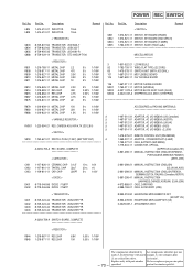
...SET (US) X-3329-657-1 ATTACHMENT ASSY A-3293-759-A SWITCH BOARD, COMPLETE < RESISTOR > R844 1-218-867-11 RES,CHIP R845 1-218-871-11 RES,CHIP 6.8K 0.50% 1/16W 10K 0.50% 1/16W - 73 - or dotted line with part number...21 REMOTE CONTROL UNIT (RM-MZR50) 1-569-007-11 ADAPTOR, CONVERSION 2P (E,JEW) 1-759-277-21 CASE, BATTERY (EBP-MZR4) 1-779-504-11 CONNECTOR, OPTICAL (AEP,FR,UK,Canadian,HK) 3-861-298-11 MANUAL, INSTRUCTION (ENGLISH,SPANISH...MODULE 52 1-782-709-11 WIRE (FLAT TYPE) (22 CORE) 65 1-475-378-11 SWITCH UNIT (WITH JOG DIAL) 101 1-667-210-11 MD FLEXIBLE BOARD 104 1-667-690-11 CLV ...
...SET (US) X-3329-657-1 ATTACHMENT ASSY A-3293-759-A SWITCH BOARD, COMPLETE < RESISTOR > R844 1-218-867-11 RES,CHIP R845 1-218-871-11 RES,CHIP 6.8K 0.50% 1/16W 10K 0.50% 1/16W - 73 - or dotted line with part number...21 REMOTE CONTROL UNIT (RM-MZR50) 1-569-007-11 ADAPTOR, CONVERSION 2P (E,JEW) 1-759-277-21 CASE, BATTERY (EBP-MZR4) 1-779-504-11 CONNECTOR, OPTICAL (AEP,FR,UK,Canadian,HK) 3-861-298-11 MANUAL, INSTRUCTION (ENGLISH,SPANISH...MODULE 52 1-782-709-11 WIRE (FLAT TYPE) (22 CORE) 65 1-475-378-11 SWITCH UNIT (WITH JOG DIAL) 101 1-667-210-11 MD FLEXIBLE BOARD 104 1-667-690-11 CLV ...

Service Manual
Page 56
MZ-R50 9-923-258-11 Sony Corporation Personal A&V Products Company - 74 - 97L0290-1 Printed in Japan © 1997.12 Published by Quality Engineering Dept. (Shibaura)
MZ-R50 9-923-258-11 Sony Corporation Personal A&V Products Company - 74 - 97L0290-1 Printed in Japan © 1997.12 Published by Quality Engineering Dept. (Shibaura)


