Sony MZ-R50 - MD Walkman MiniDisc Recorder Support and Manuals
Get Help and Manuals for this Sony item
Most Recent Sony MZ-R50 Questions

Is The Sony Rm-mzr50 Remote Compatible With Other Md Players Besides The Mz-r50?
I own a Sony RM-MZR50 remote but I do not have a Sony MZ-R50 MiniDisc player/recorder. Are there oth...
I own a Sony RM-MZR50 remote but I do not have a Sony MZ-R50 MiniDisc player/recorder. Are there oth...
(Posted by Stormwalker65 11 years ago)
Sony MZ-R50 Videos

Minidisc Sony Mz-r50 #95
Duration: :36
Total Views: 142
Duration: :36
Total Views: 142
SONY MD Walkman MZ-R50 Jamiroquai
Duration: :16
Total Views: 3,047
Duration: :16
Total Views: 3,047
Sony Minidisc MZ-R50
Duration: :42
Total Views: 763
Duration: :42
Total Views: 763
Sony Minidisc MZ-R50
Duration: 2:25
Total Views: 1,300
Duration: 2:25
Total Views: 1,300
Popular Sony MZ-R50 Manual Pages
Service Manual - Page 1
...-280A
SPECIFICATIONS
System Audio playing system MiniDisc digital audio system Laser diode properties Material: GaAIAs Wavelength: λ = 780 nm Emission duration: continuous Laser output: less than 44.6 µW (This output is the value measured at a distance of 200 mm from the lens surface on page 2 - SERVICE MANUAL
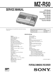
MZ-R50
US Model Canadian Model
AEP Model UK Model E Model
Australian Model...
Service Manual - Page 2
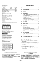
... OF CONTENTS
Specifications 1
1. SERVICING NOTE 3
2. GENERAL Location and Function of IC Terminals 35 6-2. Main Section 45 6-5. Main (2/3) Section 53 6-7. EXPLODED VIEWS 7-1. Mechanism Deck Section 67
8.
COMPONENTS IDENTIFIED BY MARK ! REPLACE THESE COMPONENTS WITH SONY PARTS WHOSE PART NUMBERS APPEAR AS SHOWN IN THIS MANUAL OR IN SUPPLEMENTS PUBLISHED BY SONY. ATTENTION AU...
Service Manual - Page 20
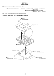
...)
1 Screws (M1.4 precision pan)
Upper panel assy
3
2 Knob (Open)
Bottom panel assy 7
6 Screw (M1.4 precision pan)
4 Screws (M1.4 precision pan)
5 Screws (M1.4 precision pan)
- 20 - Set Upper panel assy, Bottom panel assy
Main board
Mechanism deck
Battery case assy
Note : Follow the disassembly procedure in the numerical order given. 3-1.
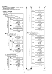
Service Manual - Page 28
... test
" key
p key
Mode : 121 Manual recording
(LINE, MIC)
p key
" key
Mode : 122 DEMP Manual recording
(LINE, MIC)
p key
" key
Mode : 123 AGC recording (LINE, OPT, MIC)
p key
" key
Mode : 124 DEMP AGC recording
(LINE, OPT, MIC)
" key
p key
DigitaM l
Mode : 130 AGC adjustment
1
" key
VOLUME +key or - [Audio Mode] • Set the test mode, press the...
Service Manual - Page 30
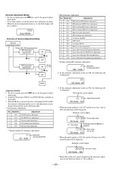
...Error code (01 to 04)
* When the mode number is 039, 061 and the AT error rate is NG, the following will
be displayed. Mode No. (Last 2 digits)
39 03 CD mode NG
AT error value
* When NG, set the general adjust- Set...adjustment
2
033 MO playback ABCD level adjustment
3
034 MO recording EF balance adjustment
4
035 MO recording ABCD level adjustment
5
037 MO focus gain adjustment
6
038...
Service Manual - Page 32
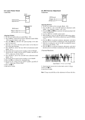
...- 32 - Open the cover and set the laser power adjustment mode (Mode
: 020) using the volume + and - Press the " key, and set the MO recording EF balance adjustment mode (Mode : ...and set the laser power meter on the market. 5. Check that the voltage between AP574 (LDIO) and AP5117
(VCC) at this time is symmetrical at the top and bottom.
(Traverse Waveform)
A
0V
C
B
Specification ...
Service Manual - Page 33
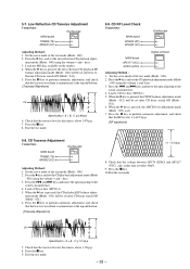
... (Mode : 051). 6. Check that the traverse level at this time is symmetrical at the top and bottom. (Traverse Waveform)
A
0V
C
B
Specification : A = B, C >= 0.9Vp-p
6. When the " key is above 0.9Vp-p. 7. Exit the test mode.
5-9. Press the " key, and set the CD playback adjustment mode (Mode
: 050) using the volume + and - Press the " key, and...
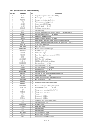
Service Manual - Page 36
...servo drive signal output (+). Not used (Open). O EFM recording signal ouput.
- 36 - I Laser power setting signal input. -
I Input of tracking error signal from RF amplifier (IC501). Not used (Connect to ...8V).
- Not used (Connect to RF amplifier (IC501). I Input focus error signal from spindle motor driver (IC701).
- I FG signal input from RF amplifier (IC501). I Input...
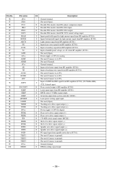
Service Manual - Page 37
...L : DC IN
-
System clock (12MHz).
-
Internal circuit : L
I CLOCK SET switch input.
I SYNCHRO REC switch input.
I Electric volume control data input. I ...used (Open). O LCD standby output.
O REC LED control. L : ON
- Chip Select input (Connected to remote control. Not used (Open). O Reset output. O Laser ON signal. H : Protect
O Data output to +2.8V...
Service Manual - Page 40
...Replace only with mark !
r Refer to page 61 for electrolytics
and tantalums. • All resistors are in µF unless otherwise noted. Les composants identifiés
fied by mark ! line with part... TIME/DIV : 20nsec
Note: • All capacitors are cri- Note:
Note:
The components identi- MZ-R50 sont cri-
numéro spécifié.
• A : B+ Line.
• ...
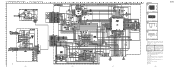
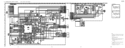
Service Manual - Page 41
... may be noted due to page 62 for electrolytics
and tantalums.
• All resistors are in µF unless otherwise noted.
tion tolerances.
• Signal path.
MZ-R50
6-6. pF: µµF
50 WV or less are not indicated except for IC Block Diagrams.
Note:
• All capacitors are taken with respect to ground...
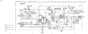
Service Manual - Page 42
... from external power voltage jack (J901).
• Voltages and waveforms are in µF unless otherwise noted.
tion tolerances.
• Circled numbers refer to normal produc-
MZ-R50
r WAVEFORMS
5
2.3Vp-p
12MHz
IC801 $º
6
VOLT/DIV : 1V AC TIME/DIV : 20nsec
0.8Vp-p
32kHz
IC804 2 VOLT/DIV : 0.1V AC TIME/DIV : 10µsec
Note...
Service Manual - Page 50
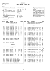
... C109 C110
C117 C118 C120 C121 C122
Part No. Replace only with mark ! When indicating parts by mark ! No. CHIP 1-119-... CHIP 1-117-919-11 TANTAL. are seldom required for routine service. CHIP 1-119-660-11 TANTAL. sont critiques pour la sé...be different from the parts specified in the diagrams or the components used on the set. • -XX, -X mean standardized parts, so they may be...
Service Manual - Page 55
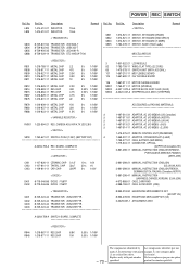
...REMOTE CONTROL UNIT (RM-MZR50) 1-569-007-11 ADAPTOR, CONVERSION 2P (E,JEW) 1-759-277-21 CASE, BATTERY (EBP-MZR4) 1-779-504-11 CONNECTOR, OPTICAL
(AEP,FR,UK,Canadian,HK) 3-861-298-11 MANUAL, INSTRUCTION...-210-11 MD FLEXIBLE BOARD
...SET (EXCEPT US)
8-953-278-90 HEADPHONE MDR-A34SP SET...Replace only with mark marque ! L804 L805
Q803 Q804 Q805 Q888
R801 R808 R809 R810 R811
R812 R814 R815 R867 R875
Part...
Service Manual - Page 56
MZ-R50
9-923-258-11
Sony Corporation
Personal A&V Products Company
- 74 -
97L0290-1 Printed in Japan © 1997.12 Published by Quality Engineering Dept.
(Shibaura)
Sony MZ-R50 Reviews
We have not received any reviews for Sony yet.