
Operating Instructions
Page 33
...) The recorder can also change play modes (repeat play, or shuffle play modes" (page 34). • In group mode, pressing > on the recorder or the remote control during the last track of the group moves playback to the last track of the group, and pressing .
...) The recorder can also change play modes (repeat play, or shuffle play modes" (page 34). • In group mode, pressing > on the recorder or the remote control during the last track of the group moves playback to the last track of the group, and pressing .

Operating Instructions
Page 46
...level. or > repeatedly until "OFF" flashes in the display, and then press ENTER. 3 Press . Turning off the beep sound on the optional remote control. 5 Press . or > repeatedly until "BEEP" flashes in step 4. To cancel AVLS Select "OFF" in the display and then press ENTER. 4 Press... . REMOTE: when turning off the beep sound. ./> MENU/ ENTER 1 Press MENU. 2 Press . To turn off the beep sound on the recorder. Other Operations ...
...level. or > repeatedly until "OFF" flashes in the display, and then press ENTER. 3 Press . Turning off the beep sound on the optional remote control. 5 Press . or > repeatedly until "BEEP" flashes in step 4. To cancel AVLS Select "OFF" in the display and then press ENTER. 4 Press... . REMOTE: when turning off the beep sound. ./> MENU/ ENTER 1 Press MENU. 2 Press . To turn off the beep sound on the recorder. Other Operations ...
Operating Instructions
Page 57
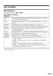
...). Selecting the start point when recording (page 29). • LPStmp - P-MODE Selecting play mode (repeat play, shuffle play, etc.) (page 34). Menu on "M-UNIT" or "REMOTE" (page 46). • R-Posi - BASS Selecting "BASS 1" or "BASS 2" (DIGITAL MEGA BASS) (page 35). RecVol Selecting the automatic or manual recording level adjustment (page 31...
...). Selecting the start point when recording (page 29). • LPStmp - P-MODE Selecting play mode (repeat play, shuffle play, etc.) (page 34). Menu on "M-UNIT" or "REMOTE" (page 46). • R-Posi - BASS Selecting "BASS 1" or "BASS 2" (DIGITAL MEGA BASS) (page 35). RecVol Selecting the automatic or manual recording level adjustment (page 31...

Operating Instructions
Page 59
or >. Press CANCEL on the recorder to cancel a menu operation. 59-GB continued from the previous page , : Pressing ENTER h : Pressing . SYNC-R OFF OPTION AVLS ON BEEP R-Posi3) LPStmp OFF ON FrHere Fr End M-UNIT REMOTE4) ON OFF ON OFF ON OFF 1) Appears only when the recorder is in group mode and a group other than "GP --" is selected. 2) Appears only when the recorder is in group mode. 3) Selectable only when group mode is turned off. 4) Appears only when the optional remote control is used.
or >. Press CANCEL on the recorder to cancel a menu operation. 59-GB continued from the previous page , : Pressing ENTER h : Pressing . SYNC-R OFF OPTION AVLS ON BEEP R-Posi3) LPStmp OFF ON FrHere Fr End M-UNIT REMOTE4) ON OFF ON OFF ON OFF 1) Appears only when the recorder is in group mode and a group other than "GP --" is selected. 2) Appears only when the recorder is in group mode. 3) Selectable only when group mode is turned off. 4) Appears only when the optional remote control is used.

Marketing Specifications
Page 2
MZ-N505 features ◗ HIGH SPEED NET MD™ WALKMAN® PLAYER/RECORDER provides ability to transfer internet downloads and music ripped from your CDs, creating your own MiniDisc music mixes for on PC specifications. ** Reduces or eliminates skipping during many active uses Sony Electronics Inc • 1 Sony... 20-20,000Hz +/-3dB WOW AND FLUTTER: Unmeasurable INPUT: DC In, 3V USB (mini-B) Optical Line In (stereo mini) OUTPUTS: Headphones/Remote: Stereo mini jack POWER REQUIREMENTS: AC Adaptor (AC-ES305) (supplied) NH-WMAA Rechargeable Battery (optional) "AA" Alkaline Battery x 1 (...
MZ-N505 features ◗ HIGH SPEED NET MD™ WALKMAN® PLAYER/RECORDER provides ability to transfer internet downloads and music ripped from your CDs, creating your own MiniDisc music mixes for on PC specifications. ** Reduces or eliminates skipping during many active uses Sony Electronics Inc • 1 Sony... 20-20,000Hz +/-3dB WOW AND FLUTTER: Unmeasurable INPUT: DC In, 3V USB (mini-B) Optical Line In (stereo mini) OUTPUTS: Headphones/Remote: Stereo mini jack POWER REQUIREMENTS: AC Adaptor (AC-ES305) (supplied) NH-WMAA Rechargeable Battery (optional) "AA" Alkaline Battery x 1 (...

Service Manual
Page 2
... NC-WMAA Nickel Cadmium rechargeable battery (European model only) (1) AC power adaptor (1) Headphones/earphones with a remote control (1) Optical cable (European model only) (1) USB cable (1) Battery carrying case (1) Carrying case with ... Technology Industries Association) standard. 4) When using a 100% fully charged rechargeable battery. 5) When using a Sony LR6 (SG) "STAMINA " alkaline dry battery (produced in .) without notice. COMPONENTS IDENTIFIED BY MARK 0...(w/h/d) (31/4 × 11/8 × 3 in Japan). MZ-N505 Coding ATRAC (Adaptive TRansform Acoustic Coding) AT RAC3 -
... NC-WMAA Nickel Cadmium rechargeable battery (European model only) (1) AC power adaptor (1) Headphones/earphones with a remote control (1) Optical cable (European model only) (1) USB cable (1) Battery carrying case (1) Carrying case with ... Technology Industries Association) standard. 4) When using a 100% fully charged rechargeable battery. 5) When using a Sony LR6 (SG) "STAMINA " alkaline dry battery (produced in .) without notice. COMPONENTS IDENTIFIED BY MARK 0...(w/h/d) (31/4 × 11/8 × 3 in Japan). MZ-N505 Coding ATRAC (Adaptive TRansform Acoustic Coding) AT RAC3 -

Service Manual
Page 5
... the disc and track names, error messages, track numbers, etc. H T MARK button I Battery indication Shows approximate battery condition. SECTION 2 GENERAL MZ-N505 This section is in record standby mode. button B x (stop )/CHARGE button CHARGE 7 8 9 q; qa qs qd qf qg G Display ...I A ./>/N (search/AMS/play mode of the MD being played or recorded. E Level meter Shows the volume of the MD. 10 11 The headphones/earphoneswith a remote control F A B G C H D E I J K LM N A MONO (monaural) indication B LP mode indication C Mega bass indication D Disc indication ...
... the disc and track names, error messages, track numbers, etc. H T MARK button I Battery indication Shows approximate battery condition. SECTION 2 GENERAL MZ-N505 This section is in record standby mode. button B x (stop )/CHARGE button CHARGE 7 8 9 q; qa qs qd qf qg G Display ...I A ./>/N (search/AMS/play mode of the MD being played or recorded. E Level meter Shows the volume of the MD. 10 11 The headphones/earphoneswith a remote control F A B G C H D E I J K LM N A MONO (monaural) indication B LP mode indication C Mega bass indication D Disc indication ...

Service Manual
Page 13
...connect pin t>t.t.t>t . If a fault is performed with the set. play. While pressing the x key, press the keys on LCDs of the set and the remote commander. 13 Set LCD display SETTING METHOD OF TEST MODE There are three different methods to set the test mode: All lit 1 Short SL801 (TEST..., the system displays its location. tX tX 3 In the normal mode, turn on the MAIN board with the following dis- SECTION 4 TEST MODE MZ-N505 OUTLINE • This set provides the Overall adjustment mode that allows CD and MO discs to be automatically adjusted when in the text, indicates a set...
...connect pin t>t.t.t>t . If a fault is performed with the set. play. While pressing the x key, press the keys on LCDs of the set and the remote commander. 13 Set LCD display SETTING METHOD OF TEST MODE There are three different methods to set the test mode: All lit 1 Short SL801 (TEST..., the system displays its location. tX tX 3 In the normal mode, turn on the MAIN board with the following dis- SECTION 4 TEST MODE MZ-N505 OUTLINE • This set provides the Overall adjustment mode that allows CD and MO discs to be automatically adjusted when in the text, indicates a set...

Service Manual
Page 17
MZ-N505 SOUND SKIP CHECK RESULT DISPLAY MODE This set can display the count of errors that occurred during this display, the remote commander LCD switches to the test mode (display check mode), press the x key. • Setting Method of sound skip check each item (hex.) ######: 6-... last two digits, AD value of error Sound error correction error Decoder status error Address access error Buffer is empty Buffer is displayed in hexadecimal) Remote commander LCD display 004 3. Press the N key or N and [T MARK/REC] keys, and the playing or recording sound skip result display mode becomes...
MZ-N505 SOUND SKIP CHECK RESULT DISPLAY MODE This set can display the count of errors that occurred during this display, the remote commander LCD switches to the test mode (display check mode), press the x key. • Setting Method of sound skip check each item (hex.) ######: 6-... last two digits, AD value of error Sound error correction error Decoder status error Address access error Buffer is empty Buffer is displayed in hexadecimal) Remote commander LCD display 004 3. Press the N key or N and [T MARK/REC] keys, and the playing or recording sound skip result display mode becomes...

Service Manual
Page 18
Example1: When the keys on the set and on the remote commander are shown for 4 seconds. When all the keys on the set are considered as OK: Set LCD display 888 SET OK Example2: When the keys on the remote commander are considered as OK, the following displays are considered as OK: Set LCD display 888 RMC OK 5. When all keys were checked or if the upper panel is opened, the key check mode quits and the test mode (display check mode) comes back. 18 MZ-N505 4.
Example1: When the keys on the set and on the remote commander are shown for 4 seconds. When all the keys on the set are considered as OK: Set LCD display 888 SET OK Example2: When the keys on the remote commander are considered as OK, the following displays are considered as OK: Set LCD display 888 RMC OK 5. When all keys were checked or if the upper panel is opened, the key check mode quits and the test mode (display check mode) comes back. 18 MZ-N505 4.

Service Manual
Page 19
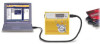
... must be made with pressing the [END SEARCH] key in the overall adjustment mode. 4. Remote commander LCD display 021 Res*** NV reset (after the NV was reset. Temperature Correction" and... 4. CD Overall Adjustment r 7. SECTION 5 ELECTRICAL ADJUSTMENTS MZ-N505 OUTLINE • In this set, automatic adjustment of CD and MO can be performed continuously ...measuring instruments. • Test CD disc TDYS-1 (Part No. : 4-963-646-01) • SONY MO disc available on the market • Digital voltmeter • Laser power meter LPM-8001 (Part...
... must be made with pressing the [END SEARCH] key in the overall adjustment mode. 4. Remote commander LCD display 021 Res*** NV reset (after the NV was reset. Temperature Correction" and... 4. CD Overall Adjustment r 7. SECTION 5 ELECTRICAL ADJUSTMENTS MZ-N505 OUTLINE • In this set, automatic adjustment of CD and MO can be performed continuously ...measuring instruments. • Test CD disc TDYS-1 (Part No. : 4-963-646-01) • SONY MO disc available on the market • Digital voltmeter • Laser power meter LPM-8001 (Part...

Service Manual
Page 26
Press the . Set the test mode (see page 13). 3. Set LCD display 000 Assy11 26 MZ-N505 OVERALL ADJUSTMENT MODE • Configuration of CD and MO Overall Adjustment Mode 1. not completed) *0: Not adjusted Note: Adjust the CD first, when performing... *F: CD overall adjustment completed *1: Manual adjustment exists (overall adj. Electrical offset adjustment is 3 V. 2. ment mode. Press the [MENU/ENTER] key on the remote commander. Set the test mode (see page 13). 2. or [VOL --] key to activate the overall adjust- key (Title display) N key Protect switch ON ...
Press the . Set the test mode (see page 13). 3. Set LCD display 000 Assy11 26 MZ-N505 OVERALL ADJUSTMENT MODE • Configuration of CD and MO Overall Adjustment Mode 1. not completed) *0: Not adjusted Note: Adjust the CD first, when performing... *F: CD overall adjustment completed *1: Manual adjustment exists (overall adj. Electrical offset adjustment is 3 V. 2. ment mode. Press the [MENU/ENTER] key on the remote commander. Set the test mode (see page 13). 2. or [VOL --] key to activate the overall adjust- key (Title display) N key Protect switch ON ...

Service Manual
Page 34
... SYSTEM CONTROLLER (IC801) B+ VIF A/D CONVERTER (IC301), SYSTEM CONTROLLER (IC801), EEPROM (IC804) B+ VA A/D CONVERTER (IC301), SYSTEM CONTROLLER (IC801) B+ VC RF AMP (IC501), MOTOR/COIL DRIVER (IC551), REMOTE CONTROL CIRCUIT B+ NOISE FILTER NOISE FILTER VRECO OVER WRITE HEAD DRIVE (IC601) B+ VREC OVER WRITE HEAD DRIVE CIRCUIT B+ L904 7 VRMC 4 XWK3 56 CLK 52 CLK...) 1PC. 1.5V CHARGE CONTROL Q602 (1/2) VBUS GND 1 CN701 (2/2) (USB CONNECTOR) 5 VIF B+ LINE FILTER T601 TH601 J601 DC IN 3V - + GROUND LINE SWITCHING Q601 34 34 MZ-N505 6-3. BLOCK DIAGRAM -
... SYSTEM CONTROLLER (IC801) B+ VIF A/D CONVERTER (IC301), SYSTEM CONTROLLER (IC801), EEPROM (IC804) B+ VA A/D CONVERTER (IC301), SYSTEM CONTROLLER (IC801) B+ VC RF AMP (IC501), MOTOR/COIL DRIVER (IC551), REMOTE CONTROL CIRCUIT B+ NOISE FILTER NOISE FILTER VRECO OVER WRITE HEAD DRIVE (IC601) B+ VREC OVER WRITE HEAD DRIVE CIRCUIT B+ L904 7 VRMC 4 XWK3 56 CLK 52 CLK...) 1PC. 1.5V CHARGE CONTROL Q602 (1/2) VBUS GND 1 CN701 (2/2) (USB CONNECTOR) 5 VIF B+ LINE FILTER T601 TH601 J601 DC IN 3V - + GROUND LINE SWITCHING Q601 34 34 MZ-N505 6-3. BLOCK DIAGRAM -

Service Manual
Page 49
...used 45 SI0 I Serial data input from the DSP monitor (3) 27 SSB DATA I/O SSB data input/output with the RF amplifier and the remote commander attached headphone 28 SSB CLK O SSB clock output to the RF amplifier 29 VREC PWM O PWM signal output for the Over write head...O Data output terminal Not used 53 KRB I /O Two-way data bus terminal for D-RAM) (+2.4V) 12, 13 DRAMVSS0, 1 - Not used 10, 11 DRAMVDD0, 1 - MZ-N505 • IC801 CXD2677-202GA (SYSTEM CONTROLLER, DIGITAL SIGNAL PROCESSOR, 16M BIT D-RAM) Pin No. Ground terminal (for D-RAM) 14, 15 NC I/O Two-way data bus...
...used 45 SI0 I Serial data input from the DSP monitor (3) 27 SSB DATA I/O SSB data input/output with the RF amplifier and the remote commander attached headphone 28 SSB CLK O SSB clock output to the RF amplifier 29 VREC PWM O PWM signal output for the Over write head...O Data output terminal Not used 53 KRB I /O Two-way data bus terminal for D-RAM) (+2.4V) 12, 13 DRAMVSS0, 1 - Not used 10, 11 DRAMVDD0, 1 - MZ-N505 • IC801 CXD2677-202GA (SYSTEM CONTROLLER, DIGITAL SIGNAL PROCESSOR, 16M BIT D-RAM) Pin No. Ground terminal (for D-RAM) 14, 15 NC I/O Two-way data bus...

Service Manual
Page 51
... supply control signal output for the OSC cell) (+2.4V) 150 OSCI I /O Serial data input/output with the remote commander attached headphone 121 TSLVDD - Pin Name I/O Description 103 XMUTE O Analog muting control signal output terminal "L": muting...terminal (A/D input) from the RF amplifier 109, 110 SET KEY 1, 2 I Key input terminal (A/D input) from the remote commander attached headphone 117 AVDD - Input "H" in other cases. 116 RMC KEY I USB data (+) input terminal 135 UPUEN... Power supply terminal (for the USB 139 USBOSCVSS - Not used 128 SAK - MZ-N505 Pin No.
... supply control signal output for the OSC cell) (+2.4V) 150 OSCI I /O Serial data input/output with the remote commander attached headphone 121 TSLVDD - Pin Name I/O Description 103 XMUTE O Analog muting control signal output terminal "L": muting...terminal (A/D input) from the RF amplifier 109, 110 SET KEY 1, 2 I Key input terminal (A/D input) from the remote commander attached headphone 117 AVDD - Input "H" in other cases. 116 RMC KEY I USB data (+) input terminal 135 UPUEN... Power supply terminal (for the USB 139 USBOSCVSS - Not used 128 SAK - MZ-N505 Pin No.

Service Manual
Page 64
... par une pièce 64 ber specified. Replace only with marque 0 sont critiques pour la mark 0 are critical for safety. MZ-N505 MAIN Ref. No. Description ACCESSORIES Remark 1-476-303-11 REMOTE CONTROL UNIT (RM-MZ4R) (AEP, UK, FR) 1-476-857-11 ADAPTOR, AC (AC-ES305) (AEP, FR) 1-476-858-11 ADAPTOR...
... par une pièce 64 ber specified. Replace only with marque 0 sont critiques pour la mark 0 are critical for safety. MZ-N505 MAIN Ref. No. Description ACCESSORIES Remark 1-476-303-11 REMOTE CONTROL UNIT (RM-MZ4R) (AEP, UK, FR) 1-476-857-11 ADAPTOR, AC (AC-ES305) (AEP, FR) 1-476-858-11 ADAPTOR...
