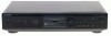
Service Manual
Page 19
..." / c = ". Rotate the AMS knob and display "FBIAS ADJUST". 6. Find points a and b in the following figure using the average vale. Load a continuously recorded disc (Refer to Servicing Note on page 4.) MDS-JE320 - 19 - - 20 - Note 1 : If the C1 error and ADER are above 00 every time. 9. Creating Continuously... Recorded Disc".). 2. If the C1 error rate is below 50, check that the C1 error rate is below 50 and ADER ...
Service Manual
Page 20
MDS-JE320 6-1. M SLED+ SLED- M SPDL+ SPDL- HF MODULE SW IC103,Q102-104 SLED/SPINDLE MOTOR DRIVE FOCUS/TRACKING COIL DRIVE IC152 10 DRIVER 12 21 DRIVER 23 ...
Service Manual
Page 21
... INDICATOR TUBE +3V (BD) 5 +3V REG IC192 1 PH +5V SYS +3.3V ANA +5V SWITCHING REG IC309 1 +5V REG 5 +3.3V REG 4 +5V REG 6 BACK UP S. RESET P. MDS-JE320 - MAIN Section -
Service Manual
Page 22
MDS-JE320 6-2. Note: The components identified by mark ! or dotted line with a VOM (Input impedance 10 MΩ). sont critiques pour la sécurité. No mark : FM ( ) : ...
Service Manual
Page 23
Location D101 E-3 D181 C-9 D183 C-9 IC101 F-14 IC103 B-15 IC121 D-12 IC122 C-4 IC123 E-10 IC124 F-12 IC152 B-12 IC171 F-9 IC181 D-9 IC192 G-6 Q101 C-14 Q102 B-15 Q103 B-14 Q104 B-14 Q162 B-14 Q163 B-15 Q180 D-6 Q181 B-9 Q182 B-9 (Page 45) 16 (Page 33) MDS-JE320 (Page 33) - 27 - - 28 - Printed Wiring Board - 6-3. No. BD Section - • See page 25 for Circuit Boards Location. • Semiconductor Location Ref.
Service Manual
Page 24
MDS-JE320 6-4. BD Section (1/2)- • See page 26 for Waveforms. • See page 49 for IC Block Diagrams. • See page 54 for IC Pin Functions. 16 (Page 31) - 29 - (Page 32) - 30 - Schematic Diagram -
Service Manual
Page 25
BD Section (2/2) - • See page 26 for Waveforms. • See page 49 for IC Block Diagrams. • See page 54 for IC Pin Functions. (Page 29) (Page 30) MDS-JE320 BR24C01AF 16 (Page 36) (Page 47) (Page 35) - 31 - - 32 - Schematic Diagram - 6-5.
Service Manual
Page 26
... R OUT L E1 1 3 36 31 7 E 1 8 1 3 14 IC353 DIGITAL OPTICAL IN EE E TR301 POWER TRANSFORMER H I J - 33 - 1 5 X X NOT REPLACEABLE: BUILT IN TRANSFORMER - 34 - 1-665-005- 21 AC IN MDS-JE320 6-6. No. Main Section - • See page 25 for Circuit Boards Location. • Semiconductor Location Ref.
Service Manual
Page 27
MDS-JE320 (PAGE 32) - 35 - (PAGE 31) - 36 - Main Section (1/3) - • See page 26 for Waveforms • See page 54 for IC Pin Functions. 6-7. Schematic Diagram -
Service Manual
Page 28
MDS-JE320 6-8. Schematic Diagram - Main Section (2/3) - • See page 26 for Waveforms. • See page 49 for IC Block Diagrams. • See page 54 for IC Pin Functions. - 37 - - 38 -
Service Manual
Page 29
6-9. Main Section (3/3) - • See page 49 for IC Block Diagram. Schematic Diagram - MDS-JE320 (PAGE 44) - 39 - - 40 -
Service Manual
Page 30
Printed Wiring Board - DISPLAY Section - • See page 25 for Circuit Boards Location. 1 2 3 4 5 6 7 8 9 A DISPLAY BOARD B C FLUORESCENT INDICATOR TUBE D 10 11 12 E E S764 1 3 21 1-661-891- (21) E F CONTROL (SW) BOARD REC LEVEL G H INPUT DIGITAL ANALOG C (PAGE 33) S762 DISPLAY/CHAR S774 S775 AMS (PUSH ENTER) 5 4 1 3 EJECT SW BOARD 1 S776 EJECT 3 CN705 21 1-661-893- (21) 1 3 I S771 S772 S780 S781 S752 S751 REC YES NO/EDIT 16 21 1-661-890- (21) - 41 - - 42 - MDS-JE320 6-10.
Service Manual
Page 31
DISPLAY Section - • See page 26 for Waveforms. - 43 - MDS-JE320 (PAGE 39) - 44 - Schematic Diagram - 6-11.
Service Manual
Page 32
Switch Section - • See page 25 for Circuit Boards Location. 1 2 3 4 5 6 7 8 9 10 11 12 13 A B C (Page 28) D E F G H I J 16 - 45 - - 46 - MDS-JE320 6-12. Printed Wiring Board -
Service Manual
Page 56
... Replace only with mark ! Ne les remplacer que par une pièce portant le numéro spécifié. 9-922-894-11 Sony Corporation Home A&V Products Company - 72 - 98F1664-1 Printed in Japan ©1998.6 Published by mark ! TR301 A-4672-133-A MOTOR ASSY, SLED A-... POSITION) #7 7-627-552-27 SCREW,PRECISION +P 1.7X2 #8 7-685-872-09 SCREW +BVTT 3X8 (S) The components identified by Quality Assurance Dept. (Shibaura) MDS-JE320 MAIN SW Ref. Description 1-249-441-11 1-249-441-11 1-249-441-11 1-249-441-11 1-249-429-11 CARBON CARBON CARBON CARBON CARBON 100K...