Service Manual
Page 2
... board (within 3 times). • Be careful not to manufacture's instructions. ON THE SCHEMATIC DIAGRAMS AND IN THE PARTS LIST ARE CRITICAL TO SAFE OPERATION. Lithiumbatteri - Brukte batterier katterier kasseres i henhold til fabrikantens VARNIG Explosionsfara vid felaktigt batteribyte. VAROITUS Parist voi räjähtää, jos se on the rear exterior. CAUTION Use of controls or adjustments or performance...
... board (within 3 times). • Be careful not to manufacture's instructions. ON THE SCHEMATIC DIAGRAMS AND IN THE PARTS LIST ARE CRITICAL TO SAFE OPERATION. Lithiumbatteri - Brukte batterier katterier kasseres i henhold til fabrikantens VARNIG Explosionsfara vid felaktigt batteribyte. VAROITUS Parist voi räjähtää, jos se on the rear exterior. CAUTION Use of controls or adjustments or performance...
Service Manual
Page 3
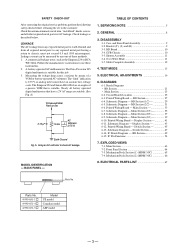
... (2) (MDM-3GC 66 8. Nearly all other exposed metal parts for this job. 3. DISASSEMBLY 3-1. Schematic Diagram - Schematic Diagram - SAFETY CHECK-OUT After correcting the original service problem, perform the following safety checks before releasing the set to the customer: Check the antenna terminals, metal trim, "metallized" knobs, screws, and all battery operated digital multimeters that is suitable for AC leakage. SUB...
... (2) (MDM-3GC 66 8. Nearly all other exposed metal parts for this job. 3. DISASSEMBLY 3-1. Schematic Diagram - Schematic Diagram - SAFETY CHECK-OUT After correcting the original service problem, perform the following safety checks before releasing the set to the customer: Check the antenna terminals, metal trim, "metallized" knobs, screws, and all battery operated digital multimeters that is suitable for AC leakage. SUB...
Service Manual
Page 4
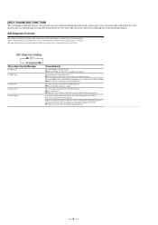
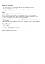
... not up to the signals of the digital program being recorded. [SELF-DIAGNOSIS FUNCTION] The self-diagnosis function consists of error codes for users which are displayed automatically when errors occur, and error codes which show the error history in the test mode during servicing.For detail on how to view error codes for users, refer to resolve the problem. While recording from a digital component connected through the digital input connector, the digital connecting cable was not made...
... not up to the signals of the digital program being recorded. [SELF-DIAGNOSIS FUNCTION] The self-diagnosis function consists of error codes for users which are displayed automatically when errors occur, and error codes which show the error history in the test mode during servicing.For detail on how to view error codes for users, refer to resolve the problem. While recording from a digital component connected through the digital input connector, the digital connecting cable was not made...
Service Manual
Page 6
... the p button. 7. Press the r REC and · PLAY buttons to display "All Erase?" The Rt value increases with each retry. When a retry error occurs, the number will be set back to be performed smoothly. Press the EDIT/NO button several times to start blinking. 5. Press the YES button. 4. When the "TOC" displayed on the fluorescent display tube. 3. If an error occurs after "TOC" disappears, disconnect the power plug from...
... the p button. 7. Press the r REC and · PLAY buttons to display "All Erase?" The Rt value increases with each retry. When a retry error occurs, the number will be set back to be performed smoothly. Press the EDIT/NO button several times to start blinking. 5. Press the YES button. 4. When the "TOC" displayed on the fluorescent display tube. 3. If an error occurs after "TOC" disappears, disconnect the power plug from...
Service Manual
Page 8
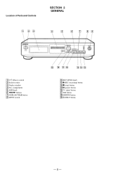
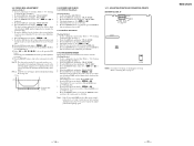
Location of Parts and Controls SECTION 2 GENERAL 1 23 4 5 6 7 89 1 1/u (Power) switch 2 Remote sensor 3 Display window 4 Disc compartment 5 AMS knob 6 0/) buttons 7 DISPLAY/CHAR button 8 INPUT switch !∞ !¢ !£ 9 REC LEVEL knob !£ r REC (recording) button !¢ p (stop) button !∞ P (pause) button !§ · (play) button !¶ YES button !• EDIT/NO button !ª § EJECT button - 8 -
Location of Parts and Controls SECTION 2 GENERAL 1 23 4 5 6 7 89 1 1/u (Power) switch 2 Remote sensor 3 Display window 4 Disc compartment 5 AMS knob 6 0/) buttons 7 DISPLAY/CHAR button 8 INPUT switch !∞ !¢ !£ 9 REC LEVEL knob !£ r REC (recording) button !¢ p (stop) button !∞ P (pause) button !§ · (play) button !¶ YES button !• EDIT/NO button !ª § EJECT button - 8 -
Service Manual
Page 13
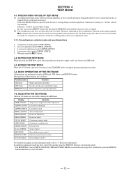
... exit from an outlet. 4-4. SETTING THE TEST MODE While pressing the AMS knob, insert the power plug into the power supply outlet, and release the AMS knob. 4-3. The functions of these buttons are performed using a disc that the disc is rotating during continuous playback, continuous recording, etc., the disc will be erased regardless of the position of disc is stopped. 2 The erasing-protection tab is not detected...
... exit from an outlet. 4-4. SETTING THE TEST MODE While pressing the AMS knob, insert the power plug into the power supply outlet, and release the AMS knob. 4-3. The functions of these buttons are performed using a disc that the disc is rotating during continuous playback, continuous recording, etc., the disc will be erased regardless of the position of disc is stopped. 2 The erasing-protection tab is not detected...
Service Manual
Page 14
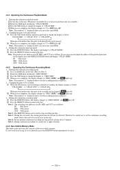
... disc. The display changes to "CREC MODE" and REC goes off . 2 When access completes, the display changes to apply vibration. 4-5-3. Changing the parts to be used in the unit. (Refer to Note 3) 2 Rotate the AMS knob and display "CREC MODE". 3 Press the YES button to change the display as below . Operating the Continuous Playback Mode 1. Note : The numbers " " displayed shows you the recording position addresses. 3. Changing the parts to be detected. Entering the continuous recording mode 1 Set a recordable disc in servicing. REC...
... disc. The display changes to "CREC MODE" and REC goes off . 2 When access completes, the display changes to apply vibration. 4-5-3. Changing the parts to be used in the unit. (Refer to Note 3) 2 Rotate the AMS knob and display "CREC MODE". 3 Press the YES button to change the display as below . Operating the Continuous Playback Mode 1. Note : The numbers " " displayed shows you the recording position addresses. 3. Changing the parts to be detected. Entering the continuous recording mode 1 Set a recordable disc in servicing. REC...
Service Manual
Page 15
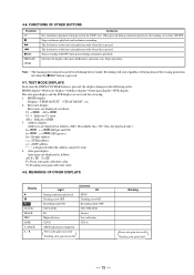
... MODE DISPLAYS Each time the DISPLAY/CHAR button is not detected during the test mode. Auto gain display Auto gains are displayed as follows. When pressed during continuous playback. T= Tracking auto gain collection value. 4-8. Stops operations. Stops continuous playback and continuous recording. C1 = AD = C1 = : Indicates C1 error AD = : Indicates ADER 3. MEANINGS OF OTHER DISPLAYS Display " P REC CLOCK TRACK DISC DATE A. Switches the display when pressed.Returns to the outer circumference only when this is pressed. 4-6. FUNCTIONS OF OTHER BUTTONS Function...
... MODE DISPLAYS Each time the DISPLAY/CHAR button is not detected during the test mode. Auto gain display Auto gains are displayed as follows. When pressed during continuous playback. T= Tracking auto gain collection value. 4-8. Stops operations. Stops continuous playback and continuous recording. C1 = AD = C1 = : Indicates C1 error AD = : Indicates ADER 3. MEANINGS OF OTHER DISPLAYS Display " P REC CLOCK TRACK DISC DATE A. Switches the display when pressed.Returns to the outer circumference only when this is pressed. 4-6. FUNCTIONS OF OTHER BUTTONS Function...
Service Manual
Page 16
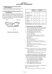
... Servicing Note on page 4.) Note :When performing laser power checks and adjustment (electrical adjustment), use of the new MD laser power meter 8010S (J-2501-145-A) instead of the laser diode during continuous recording. - 16 - Press the EDIT/NO button and stop recording . 6. After completing the adjustments, exit the test mode. 3) Perform the adjustments in focus bias adjustment and error rate check. CREATING CONTINUOUSLY RECORDED DISC • This disc...
... Servicing Note on page 4.) Note :When performing laser power checks and adjustment (electrical adjustment), use of the new MD laser power meter 8010S (J-2501-145-A) instead of the laser diode during continuous recording. - 16 - Press the EDIT/NO button and stop recording . 6. After completing the adjustments, exit the test mode. 3) Perform the adjustments in focus bias adjustment and error rate check. CREATING CONTINUOUSLY RECORDED DISC • This disc...

Service Manual
Page 17
... to stop the laser emission. (The EDIT/NO button is the same as 25 ˚C reference data. EF", "F0 - Rotate the AMS knob and display "TEMP ADJUST". 2. When not saving the data, press the EDIT/NO button. 5. Set the laser power meter on when the internal temperature of the unit is effective at that time in this part has become...
... to stop the laser emission. (The EDIT/NO button is the same as 25 ˚C reference data. EF", "F0 - Rotate the AMS knob and display "TEMP ADJUST". 2. When not saving the data, press the EDIT/NO button. 5. Set the laser power meter on when the internal temperature of the unit is effective at that time in this part has become...
Service Manual
Page 18
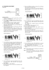
... §EJECT button and remove the check disc (MD) TDYS-1. A VC B Specification A = B 9. TRAVERSE ADJUSTMENT Connection : Oscilloscope BD board CN110 pin 3 (TEO) CN110 pin 2 (VC) V : 0.5 V/div H : 10 ms/div Input : DC mode Adjusting method : 1. Press the YES button and display "EFB = MO-R". (Laser power READ power/Focus servo ON/tracking servo OFF/spindle (S) servo ON) 6. Then "EFB = MO-W" will be erased during if a recorded disc is rotated...
... §EJECT button and remove the check disc (MD) TDYS-1. A VC B Specification A = B 9. TRAVERSE ADJUSTMENT Connection : Oscilloscope BD board CN110 pin 3 (TEO) CN110 pin 2 (VC) V : 0.5 V/div H : 10 ms/div Input : DC mode Adjusting method : 1. Press the YES button and display "EFB = MO-R". (Laser power READ power/Focus servo ON/tracking servo OFF/spindle (S) servo ON) 6. Then "EFB = MO-W" will be erased during if a recorded disc is rotated...
Service Manual
Page 19
... display changes to "5-4. Press the EDIT/NO button, stop playback, press the §EJECT button, and remove the continuously recorded disc. 5-10. Rotate the AMS knob and display "CPLAY MODE". 3. Load a continuously recorded disc (Refer to "C1 = AD = ". 5. Rotate the AMS knob and display "CPLAY MODE". 3. FOCUS BIAS ADJUSTMENT Adjusting Method : 1. Creating Continuously Recorded Disc".). 2. Press the EDIT/NO button when "C1 = AD = " is displayed. 5. The first four digits indicate the C1 error...
... display changes to "5-4. Press the EDIT/NO button, stop playback, press the §EJECT button, and remove the continuously recorded disc. 5-10. Rotate the AMS knob and display "CPLAY MODE". 3. Load a continuously recorded disc (Refer to "C1 = AD = ". 5. Rotate the AMS knob and display "CPLAY MODE". 3. FOCUS BIAS ADJUSTMENT Adjusting Method : 1. Creating Continuously Recorded Disc".). 2. Press the EDIT/NO button when "C1 = AD = " is displayed. 5. The first four digits indicate the C1 error...
Service Manual
Page 21
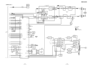
...XOUT-T 24 XIN-T 25 XOUT 27 XIN 28 96 LIMITIN 98 REFLECT 97 PROTECT 6 CHUCK IN 8 PACK OUT 38 PLAY P 37 REC P KEY0 3 KEY1 4 KEY2 5 JOG1 50 JOG0 51 SORCE 10 SYSTEM CONTROL IC316 75 LD ON 80 WRPWR 86 MOD 5 94 LD IN LED0 43 REMOCOM 14 16 @ @ LOAD-OUT ... omitted. • Signal path. : PB : REC : REC (Digital in) DIGITAL ANALOG INPUT S702 LED SW Q701,702 D701 POWER 3 RM SIRCS RECEIVER IC702 DISPLAY DRIVER IC701 62 SCK 63 SDATA 61 CS 60 RST S1 4 S36 39 G1 40 G15 54 AC FL701 FLUORESCENT INDICATOR TUBE +3V (BD) 5 +3V REG IC192 1 PH +5V SYS +3.3V ANA +5V SWITCHING REG IC309 1 +...
...XOUT-T 24 XIN-T 25 XOUT 27 XIN 28 96 LIMITIN 98 REFLECT 97 PROTECT 6 CHUCK IN 8 PACK OUT 38 PLAY P 37 REC P KEY0 3 KEY1 4 KEY2 5 JOG1 50 JOG0 51 SORCE 10 SYSTEM CONTROL IC316 75 LD ON 80 WRPWR 86 MOD 5 94 LD IN LED0 43 REMOCOM 14 16 @ @ LOAD-OUT ... omitted. • Signal path. : PB : REC : REC (Digital in) DIGITAL ANALOG INPUT S702 LED SW Q701,702 D701 POWER 3 RM SIRCS RECEIVER IC702 DISPLAY DRIVER IC701 62 SCK 63 SDATA 61 CS 60 RST S1 4 S36 39 G1 40 G15 54 AC FL701 FLUORESCENT INDICATOR TUBE +3V (BD) 5 +3V REG IC192 1 PH +5V SYS +3.3V ANA +5V SWITCHING REG IC309 1 +...

Service Manual
Page 38
... connection pin for the RF AGC circuit Input to the RF AGC circuit The RF amplifier output is input with AC coupling User comparator output (Not used) User comparator input (Fixed at "L") External capacitor pin for cutting the low band of the ADIP amplifier User operation amplifier output (Not used) User operation amplifier inversion input (Fixed at "L") RF amplifier output Groove RF signal is input with AC coupling Groove RF signal output • Abbreviation APC: Auto Power Control...
... connection pin for the RF AGC circuit Input to the RF AGC circuit The RF amplifier output is input with AC coupling User comparator output (Not used) User comparator input (Fixed at "L") External capacitor pin for cutting the low band of the ADIP amplifier User operation amplifier output (Not used) User operation amplifier inversion input (Fixed at "L") RF amplifier output Groove RF signal is input with AC coupling Groove RF signal output • Abbreviation APC: Auto Power Control...

Service Manual
Page 39
... output in the column I System clock frequency setting "L": 45.1584 MHz, "H": 22.5792 MHz (Fixed at "H") 19 DVDD - +3V power supply (Digital) 20 DVSS - Ground (Digital) 21 DIN I Digital audio input (Optical input) 22 DOUT O Digital audio output (Optical output) 23 ADDT I (S) Reset signal input from the A/D converter 24 DADT O Data output to A08 O O DRAM address output (Used : CXD2652AR, Not used ) I /O - 55 - • IC121 Digital Signal Processor, Digital Servo Signal Processor, EFM/ACIRC Encoder/Decoder, Shock-proof Memory Controller...
... output in the column I System clock frequency setting "L": 45.1584 MHz, "H": 22.5792 MHz (Fixed at "H") 19 DVDD - +3V power supply (Digital) 20 DVSS - Ground (Digital) 21 DIN I Digital audio input (Optical input) 22 DOUT O Digital audio output (Optical output) 23 ADDT I (S) Reset signal input from the A/D converter 24 DADT O Data output to A08 O O DRAM address output (Used : CXD2652AR, Not used ) I /O - 55 - • IC121 Digital Signal Processor, Digital Servo Signal Processor, EFM/ACIRC Encoder/Decoder, Shock-proof Memory Controller...

Service Manual
Page 40
...an external VCO (Fixed at "L") O Playback EFM duplex signal output I (A) Playback EFM comparator slice level input - +3V power supply (Analog) I (A) Playback EFM comparator bias current input I (A) Playback EFM RF signal input - Ground (Analog) I (A) Sled error signal input from the CXA2523R I (A) Tracking error signal input from the CXA2523R I (A) Auxiliary A/D input (Fixed at "L") I (A) Connected to +3V power supply I (A) Error signal input for the laser digital APC (Fixed at "L") I (S) ADIP duplex FM signal input from the CXA2523R (22.05 ± 1 kHz) O Filter f0 control output...
...an external VCO (Fixed at "L") O Playback EFM duplex signal output I (A) Playback EFM comparator slice level input - +3V power supply (Analog) I (A) Playback EFM comparator bias current input I (A) Playback EFM RF signal input - Ground (Analog) I (A) Sled error signal input from the CXA2523R I (A) Tracking error signal input from the CXA2523R I (A) Auxiliary A/D input (Fixed at "L") I (A) Connected to +3V power supply I (A) Error signal input for the laser digital APC (Fixed at "L") I (S) ADIP duplex FM signal input from the CXA2523R (22.05 ± 1 kHz) O Filter f0 control output...

Service Manual
Page 44
... input from the CXD2650R or I Track jump signal input from the playback position detection switch 39 LOAD V O Loading motor voltage control output 40 - Not used - 20 SYSTEM-RST System reset signal input I For several hundreds msec after the power supply rises, "L" is output when test mode (Not used ) 3 to 5 KEY 0 to the power supply circuit Power supply ON: "H", stand by: "L" 37 REC P I Detection signal input from the recording position detection switch 38 PLAY P I Detection signal input...
... input from the CXD2650R or I Track jump signal input from the playback position detection switch 39 LOAD V O Loading motor voltage control output 40 - Not used - 20 SYSTEM-RST System reset signal input I For several hundreds msec after the power supply rises, "L" is output when test mode (Not used ) 3 to 5 KEY 0 to the power supply circuit Power supply ON: "H", stand by: "L" 37 REC P I Detection signal input from the recording position detection switch 38 PLAY P I Detection signal input...

Service Manual
Page 46
...3V power supply *1 Loading motor control Operation Pin IN LOAD IN 95 pin "H" LOAD OUT 94 pin "L" OUT "L" "H" Brake "H" "H" - 62 - Not used Writing data transmission timing output to the CXD2650R or CXD2652AR O Shared with low reflection rate: "H" - Not used ) O Reset signal output to the D/A, A/D converter Reset: "L" O Digital input selection signal output Laser modulation switching signal output Playback power: "L", stop: "H" Recording power: 0.5S O 2S - - Not used O Line out muting output O O Loading motor control output *1 Detection input from the limit switch I Sled...
...3V power supply *1 Loading motor control Operation Pin IN LOAD IN 95 pin "H" LOAD OUT 94 pin "L" OUT "L" "H" Brake "H" "H" - 62 - Not used Writing data transmission timing output to the CXD2650R or CXD2652AR O Shared with low reflection rate: "H" - Not used ) O Reset signal output to the D/A, A/D converter Reset: "L" O Digital input selection signal output Laser modulation switching signal output Playback power: "L", stop: "H" Recording power: 0.5S O 2S - - Not used O Line out muting output O O Loading motor control output *1 Detection input from the limit switch I Sled...
Service Manual
Page 51
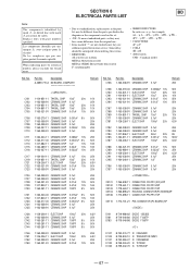
... by reference number, please include the board name. • Due to standardization, replacements in the parts list may be anticipated when ordering these items. • RESISTORS All resistors are critical for routine service. Description 1-...used on the set. • -XX, -X mean standardized parts, so they may have some difference from the parts specified in ohms METAL: Metal-film resistor METAL OXIDE: Metal Oxide-film resistor F : nonflammable • SEMICONDUCTORS In each case, u: µ , for example: uA...: µ A..., uPA...: µ PA..., uPB...: µ PB..., uPC...
... by reference number, please include the board name. • Due to standardization, replacements in the parts list may be anticipated when ordering these items. • RESISTORS All resistors are critical for routine service. Description 1-...used on the set. • -XX, -X mean standardized parts, so they may have some difference from the parts specified in ohms METAL: Metal-film resistor METAL OXIDE: Metal Oxide-film resistor F : nonflammable • SEMICONDUCTORS In each case, u: µ , for example: uA...: µ A..., uPA...: µ PA..., uPB...: µ PB..., uPC...
Service Manual
Page 56
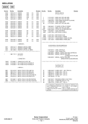
...-11 TRANSFORMER, POWER (US,CND) 1-431-426-21 TRANSFORMER, POWER (AEP) ACCESSORIES & PACKING MATERIALS 1-574-264-11 1-776-263-51 3-864-669-11 3-864-669-21 3-864-669-31 CORD, LIGHT PLUG CORD, CONNECTION MANUAL, INSTRUCTION (ENGLISH/FRENCH) MANUAL, INSTRUCTION (AEP) (CHINESE/DUTCH/ITALIAN) MANUAL, INSTRUCTION (AEP) (... PRECISION SCREW +P 2X2 TYPE 3 S688 1-762-621-21 SWITCH, PUSH (1 KEY)(REC POSITION) #7 7-627-552-27 SCREW,PRECISION +P 1.7X2 #8 7-685-872-09 SCREW +BVTT 3X8 (S) The components identified by Quality Assurance Dept. (Shibaura) Replace only with mark ! ...
...-11 TRANSFORMER, POWER (US,CND) 1-431-426-21 TRANSFORMER, POWER (AEP) ACCESSORIES & PACKING MATERIALS 1-574-264-11 1-776-263-51 3-864-669-11 3-864-669-21 3-864-669-31 CORD, LIGHT PLUG CORD, CONNECTION MANUAL, INSTRUCTION (ENGLISH/FRENCH) MANUAL, INSTRUCTION (AEP) (CHINESE/DUTCH/ITALIAN) MANUAL, INSTRUCTION (AEP) (... PRECISION SCREW +P 2X2 TYPE 3 S688 1-762-621-21 SWITCH, PUSH (1 KEY)(REC POSITION) #7 7-627-552-27 SCREW,PRECISION +P 1.7X2 #8 7-685-872-09 SCREW +BVTT 3X8 (S) The components identified by Quality Assurance Dept. (Shibaura) Replace only with mark ! ...


