
Child Safety: It Makes A Difference Where Your TV Stands
Page 1
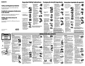
The industry is a Sector of the home with your family and friends. Thank you have a television in fact, have more than one television. As a result, TV sets may fall over . 7 Share our safety message on this hidden hazard of the Electronic Industries Alliance The Industry...safety notices. 4 Don't allow children to climb on or play with furniture and television sets. 5 Avoid placing any items on top of TVs such as VCRs and remotes that may cause unnecessary injury. Sometimes televisions are not always supported on dressers, bookcases, shelves, desks, audio speakers, chests or...
The industry is a Sector of the home with your family and friends. Thank you have a television in fact, have more than one television. As a result, TV sets may fall over . 7 Share our safety message on this hidden hazard of the Electronic Industries Alliance The Industry...safety notices. 4 Don't allow children to climb on or play with furniture and television sets. 5 Avoid placing any items on top of TVs such as VCRs and remotes that may cause unnecessary injury. Sometimes televisions are not always supported on dressers, bookcases, shelves, desks, audio speakers, chests or...
Safety and Regulatory Booklet
Page 1
... to avoid any chance of electric shock. ☐ Clean the cabinet of the TV with a dry soft cloth. ☐ Wipe the LCD screen gently with a soft cloth. ☐ Stubborn stains may be pulled or grabbed by Sony and to certify that could result in a fire or electric shock. Using incorrect ... These phenomena improve as a thinner, alcohol or benzine for extended periods of time, the AC power cord should not be observed when the LCD TV is damaged, liquid has been spilled or objects have unplugged the AC power cord. Please observe the Additional Safety DOs and DON'Ts to an...
... to avoid any chance of electric shock. ☐ Clean the cabinet of the TV with a dry soft cloth. ☐ Wipe the LCD screen gently with a soft cloth. ☐ Stubborn stains may be pulled or grabbed by Sony and to certify that could result in a fire or electric shock. Using incorrect ... These phenomena improve as a thinner, alcohol or benzine for extended periods of time, the AC power cord should not be observed when the LCD TV is damaged, liquid has been spilled or objects have unplugged the AC power cord. Please observe the Additional Safety DOs and DON'Ts to an...
Operating Instructions
Page 1
3-876-517-11(1) LCD Digital Color TV Operating Instructions KDL-26NL140 KDL-32NL140 KDL-37NL140 © 2008 Sony Corporation
3-876-517-11(1) LCD Digital Color TV Operating Instructions KDL-26NL140 KDL-32NL140 KDL-37NL140 © 2008 Sony Corporation
Operating Instructions
Page 2
...blurred or show poor color due to operate this equipment does cause harmful interference to radio or television reception, which can be determined by turning the equipment off and on, the user is ...TV for safety purposes, to safety during the installation. s To obtain the best picture, do not block the ventilation openings. It is required for help. To Customers Sufficient expertise is recommended to use it further. "BRAVIA" and , , BRAVIA Theatre Sync and DMPORT are trademarks of Conformity Trade Name: SONY Model: KDL-26NL140/KDL-32NL140/ KDL-37NL140 Responsible Party: Sony...
...blurred or show poor color due to operate this equipment does cause harmful interference to radio or television reception, which can be determined by turning the equipment off and on, the user is ...TV for safety purposes, to safety during the installation. s To obtain the best picture, do not block the ventilation openings. It is required for help. To Customers Sufficient expertise is recommended to use it further. "BRAVIA" and , , BRAVIA Theatre Sync and DMPORT are trademarks of Conformity Trade Name: SONY Model: KDL-26NL140/KDL-32NL140/ KDL-37NL140 Responsible Party: Sony...
Operating Instructions
Page 3
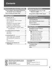
...18 4. Setting Up the Channel List Initial Setup 19 Exploring Fun Features Using BRAVIA Theatre Sync™ with Control for Wall-Mounting 8 Installing the Wall-Mount Bracket 9 When Installing the TV Against a Wall or Enclosed Area 11 2. Locating Inputs and Outputs 12 Side... Setup Guide (separate volume) Provides a variety of BRAVIA® The Four Steps to the World of optional equipment connection diagrams. Customer Support http://www.sony.com/tvsupport On-line Registration United States http://productregistration.sony.com Canada http://www.sonystyle.ca/registration 3 Contents ...
...18 4. Setting Up the Channel List Initial Setup 19 Exploring Fun Features Using BRAVIA Theatre Sync™ with Control for Wall-Mounting 8 Installing the Wall-Mount Bracket 9 When Installing the TV Against a Wall or Enclosed Area 11 2. Locating Inputs and Outputs 12 Side... Setup Guide (separate volume) Provides a variety of BRAVIA® The Four Steps to the World of optional equipment connection diagrams. Customer Support http://www.sony.com/tvsupport On-line Registration United States http://productregistration.sony.com Canada http://www.sonystyle.ca/registration 3 Contents ...

Operating Instructions
Page 4
...:9. To experience the stunning detail of your new BRAVIA TV, you will see pages 24 and 32). • This TV supports signals up to connect other external equipment Contact your BRAVIA TV is displayed on upgrading to HD programming. Your BRAVIA TV can use a boxy 4:3 aspect ratio. Welcome ...the 4:3 image to fit the entire screen (see black bars on your cable or satellite provider for purchasing this Sony BRAVIA® high-definition television. The 16:9 fills your BRAVIA TV set, a complete HD system requires an HD sound system, a source of the image you will notice a ...
...:9. To experience the stunning detail of your new BRAVIA TV, you will see pages 24 and 32). • This TV supports signals up to connect other external equipment Contact your BRAVIA TV is displayed on upgrading to HD programming. Your BRAVIA TV can use a boxy 4:3 aspect ratio. Welcome ...the 4:3 image to fit the entire screen (see black bars on your cable or satellite provider for purchasing this Sony BRAVIA® high-definition television. The 16:9 fills your BRAVIA TV set, a complete HD system requires an HD sound system, a source of the image you will notice a ...
Operating Instructions
Page 5
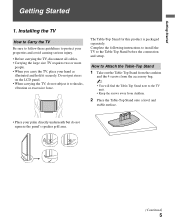
...Do not put stress on the LCD panel. • When carrying the TV, do not squeeze the panel's speaker grill area. (Continued) 5 Installing the TV How to Carry the TV Be sure to follow these guidelines to protect your properties and avoid causing serious injury. • Before carrying the TV, disconnect all cables. •...the Table-Top Stand from the cushion and the 4 screws from the accessory bag. ~ • You will find the Table-Top Stand next to the TV unit. • Keep the screws away from children. 2 Place the Table-Top Stand onto a level and stable surface. • Place your hand ...
...Do not put stress on the LCD panel. • When carrying the TV, do not squeeze the panel's speaker grill area. (Continued) 5 Installing the TV How to Carry the TV Be sure to follow these guidelines to protect your properties and avoid causing serious injury. • Before carrying the TV, disconnect all cables. •...the Table-Top Stand from the cushion and the 4 screws from the accessory bag. ~ • You will find the Table-Top Stand next to the TV unit. • Keep the screws away from children. 2 Place the Table-Top Stand onto a level and stable surface. • Place your hand ...
Operating Instructions
Page 6
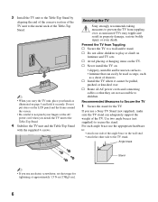
... to secure the stand. Securing the TV Sony strongly recommends taking measures to prevent the TV from Toppling s Secure the TV to a wall and/or stand. s Avoid placing or hanging items on furniture and TV sets. Angle brace Stand ~ • If you install the TV unit to the Table-Top Stand. ...at approximately 1.5 N·m {15Kgf·cm}. 6 For each angle brace use a Sony TV Stand (not supplied), make sure the TV stand can easily be pulled, pushed, or knocked over ; s Never install the TV on the LCD panel and the frame around the screen. • Be careful to not pinch your...
... to secure the stand. Securing the TV Sony strongly recommends taking measures to prevent the TV from Toppling s Secure the TV to a wall and/or stand. s Avoid placing or hanging items on furniture and TV sets. Angle brace Stand ~ • If you install the TV unit to the Table-Top Stand. ...at approximately 1.5 N·m {15Kgf·cm}. 6 For each angle brace use a Sony TV Stand (not supplied), make sure the TV stand can easily be pulled, pushed, or knocked over ; s Never install the TV on the LCD panel and the frame around the screen. • Be careful to not pinch your...

Operating Instructions
Page 7
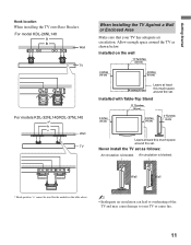
... (not supplied): • Two M6 × 12-18 mm anchor bolts (screw into the top-most wall-mount holes located on the rear of the TV) • Rope or chain (attach to one M6 anchor bolt) • Wall-anchor (attach to the wall stud) strong enough to support the weight of... the TV (pass the rope through the wall-anchor, then attach to prevent the TV from toppling over. ~ • Do not bundle the AC power cord with other M6 anchor bolt). Getting Started 2 Anchor...
... (not supplied): • Two M6 × 12-18 mm anchor bolts (screw into the top-most wall-mount holes located on the rear of the TV) • Rope or chain (attach to one M6 anchor bolt) • Wall-anchor (attach to the wall stud) strong enough to support the weight of... the TV (pass the rope through the wall-anchor, then attach to prevent the TV from toppling over. ~ • Do not bundle the AC power cord with other M6 anchor bolt). Getting Started 2 Anchor...
Operating Instructions
Page 8
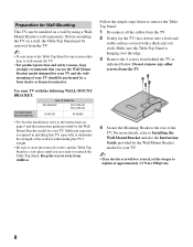
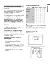
KDL-26NL140 KDL-32NL140 KDL-37NL140 SU-WL100 SU-WL500 • For bracket installation, refer to the instructions on a wall by a Sony dealer or licensed contractor. Follow the simple steps below . Do not remove any reason other screws from the TV. 2 Gently lay the TV (face down) onto a level and stable surface ...screws and the Table-Top Stand in a safe place until you use the Wall-Mount Bracket model designed for your TV and the wallmounting of the TV. Sony Wall-Mount Bracket Model No. For more details, refer to Installing the Wall-Mount Bracket and also the Instruction Guide...
KDL-26NL140 KDL-32NL140 KDL-37NL140 SU-WL100 SU-WL500 • For bracket installation, refer to the instructions on a wall by a Sony dealer or licensed contractor. Follow the simple steps below . Do not remove any reason other screws from the TV. 2 Gently lay the TV (face down) onto a level and stable surface ...screws and the Table-Top Stand in a safe place until you use the Wall-Mount Bracket model designed for your TV and the wallmounting of the TV. Sony Wall-Mount Bracket Model No. For more details, refer to Installing the Wall-Mount Bracket and also the Instruction Guide...
Operating Instructions
Page 9
... damage, read these instructions carefully. See table on the wall (Continued) 9 For product protection and safety, Sony strongly recommends that you are installing. Installation dimensions table Unit: inches (mm) TV dimensions Screen center dimensions TV Model KDL-26NL140 KDL-32NL140 KDL-37NL140 A 30 3/4 (778) 36 (912) 40 1/2 (1,028) B 18 1/2 (468) 21 1/2 (543) 24 (608) C 3 3/8 (83) 6 5/8 (168) 5 1/2 (139...
... damage, read these instructions carefully. See table on the wall (Continued) 9 For product protection and safety, Sony strongly recommends that you are installing. Installation dimensions table Unit: inches (mm) TV dimensions Screen center dimensions TV Model KDL-26NL140 KDL-32NL140 KDL-37NL140 A 30 3/4 (778) 36 (912) 40 1/2 (1,028) B 18 1/2 (468) 21 1/2 (543) 24 (608) C 3 3/8 (83) 6 5/8 (168) 5 1/2 (139...

Operating Instructions
Page 10
... remove the Table- See diagrams and table for details. 5 Install Mounting Hooks on the TV. a e, g c d, g b Screw location When installing the Mounting Hooks on the wall. See page 8 for Screw and Hook locations. 10 For models KDL-32NL140 and KDL-37NL140 Unit: inches (mm) Hook locations diagram/table TV Model KDL-26NL140 KDL-32NL140 KDL-37NL140 Screw location Hook location -
... remove the Table- See diagrams and table for details. 5 Install Mounting Hooks on the TV. a e, g c d, g b Screw location When installing the Mounting Hooks on the wall. See page 8 for Screw and Hook locations. 10 For models KDL-32NL140 and KDL-37NL140 Unit: inches (mm) Hook locations diagram/table TV Model KDL-26NL140 KDL-32NL140 KDL-37NL140 Screw location Hook location -
Operating Instructions
Page 11
... (10 cm) Leave at least this much space around the TV as follows: Air circulation is blocked. Air circulation is blocked. For model KDL-26NL140 Wall TV For models KDL-32NL140/KDL-37NL140 Wall TV When Installing the TV Against a Wall or Enclosed Area Make sure that your TV or cause fire. 11 Allow enough space around the set...
... (10 cm) Leave at least this much space around the TV as follows: Air circulation is blocked. Air circulation is blocked. For model KDL-26NL140 Wall TV For models KDL-32NL140/KDL-37NL140 Wall TV When Installing the TV Against a Wall or Enclosed Area Make sure that your TV or cause fire. 11 Allow enough space around the set...
Operating Instructions
Page 12
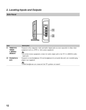
2. If your headphones. Locating Inputs and Outputs Side Panel VIDEO IN 2 VIDEO L (MONO) AUDIO R 1 2 Item 1 VIDEO IN 2 VIDEO/ L (MONO)AUDIO-R 2 Headphone jack Description Connects to the composite video and audio output jacks on your camcorder or other video equipment such as a DVD or video game equipment. • If you have mono equipment, connect its audio output jack to your headphones do not match the jack, use a suitable plug adapter (not supplied). • While headphones are connected, the TV speakers are muted. 12 Connects to the TV's L (MONO) audio input jack.
2. If your headphones. Locating Inputs and Outputs Side Panel VIDEO IN 2 VIDEO L (MONO) AUDIO R 1 2 Item 1 VIDEO IN 2 VIDEO/ L (MONO)AUDIO-R 2 Headphone jack Description Connects to the composite video and audio output jacks on your camcorder or other video equipment such as a DVD or video game equipment. • If you have mono equipment, connect its audio output jack to your headphones do not match the jack, use a suitable plug adapter (not supplied). • While headphones are connected, the TV speakers are muted. 12 Connects to the TV's L (MONO) audio input jack.

Operating Instructions
Page 13
...DMPORT Item 1 HDMI IN 1/2 R-AUDIO-L 0 56 7 8 9 Description HDMI (High-Definition Multimedia Interface) provides an uncompressed, all-digital audio/video interface between this TV displays all video input signals in a resolution of 1,366 dots × 768 lines. 2 SERVICE ONLY This USB port is for video signals only, the Audio...as PC. PC generated signals may not be rendered as expected due to your cable or VHF/UHF antenna. (Continued) 13 Note that this TV and any HDMI-equipped audio/video equipment, such as DVD player, a set-top box, A/V receiver and Blu-ray Disc player as well...
...DMPORT Item 1 HDMI IN 1/2 R-AUDIO-L 0 56 7 8 9 Description HDMI (High-Definition Multimedia Interface) provides an uncompressed, all-digital audio/video interface between this TV displays all video input signals in a resolution of 1,366 dots × 768 lines. 2 SERVICE ONLY This USB port is for video signals only, the Audio...as PC. PC generated signals may not be rendered as expected due to your cable or VHF/UHF antenna. (Continued) 13 Note that this TV and any HDMI-equipped audio/video equipment, such as DVD player, a set-top box, A/V receiver and Blu-ray Disc player as well...

Operating Instructions
Page 14
...14 You can be displayed. 8 DMPORT • For some Apple Macintosh computers, it may be necessary to use these outputs to listen to your TV's audio through your stereo system. 0 DIGITAL AUDIO Connects to the coaxial audio input of a digital audio equipment that can use an adapter (not supplied...8226; Do not connect an adapter other than the DIGITAL MEDIA PORT adapter. 9 AUDIO OUT (FIX) R/L Connects to the left side panel of the TV. Connects to a personal computer's video output connector using HD15-HD15 cable (analog RGB, not supplied). Note that has S VIDEO. Connects to the ...
...14 You can be displayed. 8 DMPORT • For some Apple Macintosh computers, it may be necessary to use these outputs to listen to your TV's audio through your stereo system. 0 DIGITAL AUDIO Connects to the coaxial audio input of a digital audio equipment that can use an adapter (not supplied...8226; Do not connect an adapter other than the DIGITAL MEDIA PORT adapter. 9 AUDIO OUT (FIX) R/L Connects to the left side panel of the TV. Connects to a personal computer's video output connector using HD15-HD15 cable (analog RGB, not supplied). Note that has S VIDEO. Connects to the ...

Operating Instructions
Page 15
... can be easily affected by subscribing to switch between the cable and over -the-air) programming, you choose (see page 33 for the type of TV SERVICE ONLY 1 2 S VIDEO VIDEO L (MONO) AUDIO R 1 VIDEO IN Y IN P B P R L AUDIO R RGB R AUDIO L DIGITAL AUDIO OUT (COAXIAL) R L 1 2 COMPONENT IN (1080i/720p/480p/480i... • It is strongly recommended that you connect the antenna/cable input using a 75-ohm coaxial cable (not supplied) to your TV via the HDMI or component video (with HDMI Connection HDMI cable CATV/ Satellite antenna cable HD cable box/HD satellite box Rear of ...
... can be easily affected by subscribing to switch between the cable and over -the-air) programming, you choose (see page 33 for the type of TV SERVICE ONLY 1 2 S VIDEO VIDEO L (MONO) AUDIO R 1 VIDEO IN Y IN P B P R L AUDIO R RGB R AUDIO L DIGITAL AUDIO OUT (COAXIAL) R L 1 2 COMPONENT IN (1080i/720p/480p/480i... • It is strongly recommended that you connect the antenna/cable input using a 75-ohm coaxial cable (not supplied) to your TV via the HDMI or component video (with HDMI Connection HDMI cable CATV/ Satellite antenna cable HD cable box/HD satellite box Rear of ...

Operating Instructions
Page 16
Shown with Component Connection CATV/ Satellite antenna cable HD cable box/HD satellite box Rear of TV SERVICE ONLY 1 2 S VIDEO VIDEO L (MONO) AUDIO R 1 VIDEO IN Y IN P B P R L AUDIO R RGB R AUDIO L DIGITAL AUDIO OUT (COAXIAL) R L 1 2 COMPONENT IN (1080i... 2 (DVI connector is for video signals only, the audio jacks provide support for the audio). Shown with DVI Connection CATV/Satellite antenna cable Rear of TV SERVICE ONLY 1 2 S VIDEO VIDEO L (MONO) AUDIO R 1 VIDEO IN Y IN P B P R L AUDIO R RGB R AUDIO L DIGITAL AUDIO OUT (COAXIAL) R L 1 2 COMPONENT IN (...
Shown with Component Connection CATV/ Satellite antenna cable HD cable box/HD satellite box Rear of TV SERVICE ONLY 1 2 S VIDEO VIDEO L (MONO) AUDIO R 1 VIDEO IN Y IN P B P R L AUDIO R RGB R AUDIO L DIGITAL AUDIO OUT (COAXIAL) R L 1 2 COMPONENT IN (1080i... 2 (DVI connector is for video signals only, the audio jacks provide support for the audio). Shown with DVI Connection CATV/Satellite antenna cable Rear of TV SERVICE ONLY 1 2 S VIDEO VIDEO L (MONO) AUDIO R 1 VIDEO IN Y IN P B P R L AUDIO R RGB R AUDIO L DIGITAL AUDIO OUT (COAXIAL) R L 1 2 COMPONENT IN (...

Operating Instructions
Page 17
...Guidelines VESA VESA Guidelines VESA VESA VESA VESA ~ • This TV's PC input does not support Sync on Green or Composite Sync. • This TV's PC VGA input does not support interlaced signals. • For...below with ferrite core (analog RGB) and audio cable (page 14). This TV can also be connected to a PC with DVI or HDMI output. (Refer to the supplied Quick Setup ...Guide.) Rear of TV HD15-HD15 cable (analog RGB) S VIDEO SERVICE ONLY Y P B VIDEO L (MONO) AUDIO R P R L AUDIO R 1 2 IN RGB R ...
...Guidelines VESA VESA Guidelines VESA VESA VESA VESA ~ • This TV's PC input does not support Sync on Green or Composite Sync. • This TV's PC VGA input does not support interlaced signals. • For...below with ferrite core (analog RGB) and audio cable (page 14). This TV can also be connected to a PC with DVI or HDMI output. (Refer to the supplied Quick Setup ...Guide.) Rear of TV HD15-HD15 cable (analog RGB) S VIDEO SERVICE ONLY Y P B VIDEO L (MONO) AUDIO R P R L AUDIO R 1 2 IN RGB R ...

Operating Instructions
Page 18
Other Equipment Personal computer Blu-ray Disc Player/ "PS3" DVD player Digital satellite receiver Digital cable box Audio system Headphones Camcorder rear of TV SERVICE ONLY 1 2 S VIDEO VIDEO L (MONO) AUDIO R 1 VIDEO IN Y IN PB PR L AUDIO R RGB R AUDIO L DIGITAL AUDIO OUT (COAXIAL) R L 1 2 COMPONENT IN (1080i/720p/480p/480i) AUDIO ... VCR Game system Digital Analog audio equipment recorder (A/V Receiver/Home Theater) ~ • Refer to the Quick Setup Guide (supplied) when connecting other equipment to your TV. 18
Other Equipment Personal computer Blu-ray Disc Player/ "PS3" DVD player Digital satellite receiver Digital cable box Audio system Headphones Camcorder rear of TV SERVICE ONLY 1 2 S VIDEO VIDEO L (MONO) AUDIO R 1 VIDEO IN Y IN PB PR L AUDIO R RGB R AUDIO L DIGITAL AUDIO OUT (COAXIAL) R L 1 2 COMPONENT IN (1080i/720p/480p/480i) AUDIO ... VCR Game system Digital Analog audio equipment recorder (A/V Receiver/Home Theater) ~ • Refer to the Quick Setup Guide (supplied) when connecting other equipment to your TV. 18


