
Service Manual
Page 1
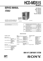
... Using Similar Mechanism NEW MD MD Mechanism Type Section Base Unit Name MDM-C1D MBU-C1 Optical Pick-up Name KMS-260A/J1N SPECIFICATIONS MICROFILM MINI Hi-Fi COMPONENT SYSTEM RM-MD515 HCD-MD515 U.S and foreign patents licensed from Dolby Laboratories Licensing Corporation. SERVICE MANUAL HCD-MD515 RM-MD515 US Model AEP Model UK Model E Model Tourist Model HCD-MD515 is the Amplifier, CD player, MD Deck and Tuner section and RM-MD515 is the Detachable Controller...
... Using Similar Mechanism NEW MD MD Mechanism Type Section Base Unit Name MDM-C1D MBU-C1 Optical Pick-up Name KMS-260A/J1N SPECIFICATIONS MICROFILM MINI Hi-Fi COMPONENT SYSTEM RM-MD515 HCD-MD515 U.S and foreign patents licensed from Dolby Laboratories Licensing Corporation. SERVICE MANUAL HCD-MD515 RM-MD515 US Model AEP Model UK Model E Model Tourist Model HCD-MD515 is the Amplifier, CD player, MD Deck and Tuner section and RM-MD515 is the Detachable Controller...

Service Manual
Page 3
... * "7 ": Play * "8 ": Pause * "9 ": Manual search (Play) - 3 - ton simultaneously and enter the test mode. 2. Press the PROGRAM button, and mechanical error count and the cout of laser power high. OPERATING THE DISPLAYED HISTORYS 1. spective operations are performed using the MULTI JOG dial and PROGRAM button. 1. Press the ENTER/YES button, therefor enter the error his- Contents total rec total play retry error total error err history err refresh (*3) Function Total time of "NO DISC" that optical system...
... * "7 ": Play * "8 ": Pause * "9 ": Manual search (Play) - 3 - ton simultaneously and enter the test mode. 2. Press the PROGRAM button, and mechanical error count and the cout of laser power high. OPERATING THE DISPLAYED HISTORYS 1. spective operations are performed using the MULTI JOG dial and PROGRAM button. 1. Press the ENTER/YES button, therefor enter the error his- Contents total rec total play retry error total error err history err refresh (*3) Function Total time of "NO DISC" that optical system...
Service Manual
Page 4
...- Notes on the disc reflective surface by heat. REPLACE THESE COMPONENTS WITH SONY PARTS WHOSE PART NUMBERS APPEAR AS SHOWN IN THIS MANUAL OR IN SUPPLEMENTS PUBLISHED BY SONY. - 4 - GENERAL 6 3. Schematic Diagram - SUB Section 44 6-6. PANEL Section 65 6-11. MD (Motor/ Sensor) Section 71 6-14. MD (Motor/ Sensor) Section 73 6-15. Printed Wiring Boards - POWER/AMPLIFIER Section 77 6-17. ELECTRICAL PARTS LIST 117 SECTION 1 SERVICING NOTES NOTES ON...
...- Notes on the disc reflective surface by heat. REPLACE THESE COMPONENTS WITH SONY PARTS WHOSE PART NUMBERS APPEAR AS SHOWN IN THIS MANUAL OR IN SUPPLEMENTS PUBLISHED BY SONY. - 4 - GENERAL 6 3. Schematic Diagram - SUB Section 44 6-6. PANEL Section 65 6-11. MD (Motor/ Sensor) Section 71 6-14. MD (Motor/ Sensor) Section 73 6-15. Printed Wiring Boards - POWER/AMPLIFIER Section 77 6-17. ELECTRICAL PARTS LIST 117 SECTION 1 SERVICING NOTES NOTES ON...
Service Manual
Page 5
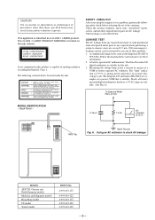
...' instructions to check AC leakage. The Simpson 250 and Sanwa SH-63Trd are suitable. (See Fig. SAFETY CHECK-OUT After correcting the original service problem, perform the following caution label is located on Set MODEL IDENTIFICATION - A commercial leakage tester, such as the Simpson 229 or RCA WT-540A. A) To Exposed Metal Parts on the rear exterior. Laser component...
...' instructions to check AC leakage. The Simpson 250 and Sanwa SH-63Trd are suitable. (See Fig. SAFETY CHECK-OUT After correcting the original service problem, perform the following caution label is located on Set MODEL IDENTIFICATION - A commercial leakage tester, such as the Simpson 229 or RCA WT-540A. A) To Exposed Metal Parts on the rear exterior. Laser component...

Service Manual
Page 6
... Unit (HCD-MD515) - SECTION 2 GENERAL 1 GROOVE button and indicator 2 Fluorescent indicator tube 3 POWER button 4 Remote sensor (for detachable controller) !¢ Detachable controller terminal - LOCATION OF CONTROLS - Detachable Controller (RM-MD515) - 1 EDIT/NO button 2 ENTER/YES button 3 POWER button 4 PRESET EQ button 5 CLOCK/TIMER SET button CLOCK/TIMER SELECT button 6 TAPE button MD button CD button TUNER (BAND) button 7 MANUAL, CONTINUE button AUTO, SHUFFLE button PRESET, PROGRAM button STEREO/MONO, REPEAT button 8 FUNCTION button 9 DISPLAY button !º ^ button !¡ p button...
... Unit (HCD-MD515) - SECTION 2 GENERAL 1 GROOVE button and indicator 2 Fluorescent indicator tube 3 POWER button 4 Remote sensor (for detachable controller) !¢ Detachable controller terminal - LOCATION OF CONTROLS - Detachable Controller (RM-MD515) - 1 EDIT/NO button 2 ENTER/YES button 3 POWER button 4 PRESET EQ button 5 CLOCK/TIMER SET button CLOCK/TIMER SELECT button 6 TAPE button MD button CD button TUNER (BAND) button 7 MANUAL, CONTINUE button AUTO, SHUFFLE button PRESET, PROGRAM button STEREO/MONO, REPEAT button 8 FUNCTION button 9 DISPLAY button !º ^ button !¡ p button...

Service Manual
Page 21
... traverse adjustment mode. multaneously to previous step. SELECTING THE TEST MODE Twenty six test modes are performed using a disc that is displayed on the set accidentally, press the POWER button immediately to the "5. If set , and select the MD function. 2. Laser power check mode (LDPWR CHECK) 5. Table 1. "TEMP ADJUST" is not to be erased in servicing. SECTION 4 TEST MODE 4-1. HEAD ADJUST CPLAY2MODE CREC2MODE Contents Temperature compensation offset check Laser power check Traverse (E-F balance) check Travers (Pre mastered...
... traverse adjustment mode. multaneously to previous step. SELECTING THE TEST MODE Twenty six test modes are performed using a disc that is displayed on the set accidentally, press the POWER button immediately to the "5. If set , and select the MD function. 2. Laser power check mode (LDPWR CHECK) 5. Table 1. "TEMP ADJUST" is not to be erased in servicing. SECTION 4 TEST MODE 4-1. HEAD ADJUST CPLAY2MODE CREC2MODE Contents Temperature compensation offset check Laser power check Traverse (E-F balance) check Travers (Pre mastered...

Service Manual
Page 22
... cluster In case you error rates and ADER. 4-7-3. Note: The numbers " " displayed shows you the recording position ad- The display will be used in the slot 1 of time above 5 minutes. 5. During the test mode, the erasing-protection tab will change the display to "CREC ( )" and REC lights up . Entering the Continuous Playback Mode 1. OPERATING THE CONTINUOUS RECORDING MODE 4-8-1. The EDIT/NO button can be careful not...
... cluster In case you error rates and ADER. 4-7-3. Note: The numbers " " displayed shows you the recording position ad- The display will be used in the slot 1 of time above 5 minutes. 5. During the test mode, the erasing-protection tab will change the display to "CREC ( )" and REC lights up . Entering the Continuous Playback Mode 1. OPERATING THE CONTINUOUS RECORDING MODE 4-8-1. The EDIT/NO button can be careful not...

Service Manual
Page 23
..., the tracking and sled servo turns on /off when pressed during the test mode. ABCD adjustment SYNC completed CLV unlock state - Releasing the test mode Disc eject Note: The erasing-protection tab in the STOP state. (servo all off . Switches between the pit and groove modes when pressed. TEST MODE DISPLAYS Each time the DISPLAY button pressed, the display changes in mode) LEVEL- Address display Address are displayed as follows. ing will start...
..., the tracking and sled servo turns on /off when pressed during the test mode. ABCD adjustment SYNC completed CLV unlock state - Releasing the test mode Disc eject Note: The erasing-protection tab in the STOP state. (servo all off . Switches between the pit and groove modes when pressed. TEST MODE DISPLAYS Each time the DISPLAY button pressed, the display changes in mode) LEVEL- Address display Address are displayed as follows. ing will start...

Service Manual
Page 29
... operated without adjust- Note: • Try to measure several times to 0 Vdc, and check this level. 9. RF LEVEL CHECK Connection: BD (CD) board TP (RF) TP (VC) oscilloscope + - Turned power switch on the SUB board) 2. Connect the lead wire to TP (TEO) and TP (VC) on the top and bottom in and press the ^ button. 7. Connect the oscilloscope to TP607. (on . (stop mode) 3. Select the CD function...
... operated without adjust- Note: • Try to measure several times to 0 Vdc, and check this level. 9. RF LEVEL CHECK Connection: BD (CD) board TP (RF) TP (VC) oscilloscope + - Turned power switch on the SUB board) 2. Connect the lead wire to TP (TEO) and TP (VC) on the top and bottom in and press the ^ button. 7. Connect the oscilloscope to TP607. (on . (stop mode) 3. Select the CD function...

Service Manual
Page 56
... I Standby signal input terminal "L": standby (fixed at "H" in AC coupling 48 MORFO O MO RF signal output terminal - 92 - IC PIN FUNCTION DESCRIPTION • BD (MD) BOARD IC101 CXA2523AR (RF AMPLIFIER, FOCUS/TRACKING ERROR AMPLIFIER) Pin No. Ground terminal 14 TEMPI I Connected to the automatic power control circuit 12 APCREF I Center frequency setting terminal for the internal circuit (BPF3T) 24 VCC - Pin Name I/O Function 1 I I I-V converted RF signal I input from the optical pick...
... I Standby signal input terminal "L": standby (fixed at "H" in AC coupling 48 MORFO O MO RF signal output terminal - 92 - IC PIN FUNCTION DESCRIPTION • BD (MD) BOARD IC101 CXA2523AR (RF AMPLIFIER, FOCUS/TRACKING ERROR AMPLIFIER) Pin No. Ground terminal 14 TEMPI I Connected to the automatic power control circuit 12 APCREF I Center frequency setting terminal for the internal circuit (BPF3T) 24 VCC - Pin Name I/O Function 1 I I I-V converted RF signal I input from the optical pick...
Service Manual
Page 57
... A/D, D/A converter (IC201) System clock signal (512Fs=22.5792 MHz) output terminal Not used (open) Input terminal for the system clock frequency setting "L": 45.1584 MHz, "H": 22.5792 MHz (fixed at "H" in this set) Power supply terminal (+3.3V) (digital system) Ground terminal (digital system) Digital audio signal input terminal when recording mode (for optical in) Digital audio signal output terminal when playback mode (for optical out) Not used Recording data input from the A/D, D/A converter (IC201) Playback...
... A/D, D/A converter (IC201) System clock signal (512Fs=22.5792 MHz) output terminal Not used (open) Input terminal for the system clock frequency setting "L": 45.1584 MHz, "H": 22.5792 MHz (fixed at "H" in this set) Power supply terminal (+3.3V) (digital system) Ground terminal (digital system) Digital audio signal input terminal when recording mode (for optical in) Digital audio signal output terminal when playback mode (for optical out) Not used Recording data input from the A/D, D/A converter (IC201) Playback...

Service Manual
Page 61
...-out signal output terminal Not used (open) Loading motor voltage control signal output to the loading motor driver Not used (open) PROTECT switch (S683) detect signal input terminal "H": protect REFLECT switch (S682) detect signal input terminal "L": high reflection rate disc, "H": low reflection rate disc MD PACK IN switch detect signal input terminal Not used (fixed at "H") PACK OUT switch detect signal input terminal Not used (fixed at "H") CHUCKING IN switch detect signal input terminal Not used (fixed at "H") LIMIT-IN switch (S681) detect signal input terminal The optical...
...-out signal output terminal Not used (open) Loading motor voltage control signal output to the loading motor driver Not used (open) PROTECT switch (S683) detect signal input terminal "H": protect REFLECT switch (S682) detect signal input terminal "L": high reflection rate disc, "H": low reflection rate disc MD PACK IN switch detect signal input terminal Not used (fixed at "H") PACK OUT switch detect signal input terminal Not used (fixed at "H") CHUCKING IN switch detect signal input terminal Not used (fixed at "H") LIMIT-IN switch (S681) detect signal input terminal The optical...

Service Manual
Page 64
... switch (S7) "L": loading in Line mute control signal output terminal Not used (open) -6 dB ATT control signal output terminal Not used (open) CD digital/optical-in convert signal output terminal to the optical-in circuit (IC641) "L": CD digital, "H": optical-in (fixed at "L" in this set) Input terminal from the reset switch (S9) "L": reset Input terminal for Japanese letter input function setting "L": input possible (fixed at "H" in this set) Digital-signal convert signal output terminal Not used (open) Not used (fixed at "L") *1 Minidisc loading motor (M903) control Terminal Operation...
... switch (S7) "L": loading in Line mute control signal output terminal Not used (open) -6 dB ATT control signal output terminal Not used (open) CD digital/optical-in convert signal output terminal to the optical-in circuit (IC641) "L": CD digital, "H": optical-in (fixed at "L" in this set) Input terminal from the reset switch (S9) "L": reset Input terminal for Japanese letter input function setting "L": input possible (fixed at "H" in this set) Digital-signal convert signal output terminal Not used (open) Not used (fixed at "L") *1 Minidisc loading motor (M903) control Terminal Operation...

Service Manual
Page 65
... system controller (IC400) and master controller (IC500) Busy signal input terminal from the master controller (IC500) Subcode sync (S0+S1) detection signal input terminal from CXD2519Q (IC103) in CD section Data read standby signal input terminal from the CD text decoder (IC104) Not used (open) JOG dial pulse input terminal Not used (fixed at "L") Power supply terminal (+5V) (for test mode setting of CD section (usually fixed at "H") Analog mute control signal output terminal Not used (open...
... system controller (IC400) and master controller (IC500) Busy signal input terminal from the master controller (IC500) Subcode sync (S0+S1) detection signal input terminal from CXD2519Q (IC103) in CD section Data read standby signal input terminal from the CD text decoder (IC104) Not used (open) JOG dial pulse input terminal Not used (fixed at "L") Power supply terminal (+5V) (for test mode setting of CD section (usually fixed at "H") Analog mute control signal output terminal Not used (open...

Service Manual
Page 66
...) in CD section Not used (open) Clock signal output terminal to the CXD2519Q (IC103) in CD section Reset/power down mode setting output terminal to the CD text decoder (IC104) Monitor input from the CXA1992AR (IC101) inside status Monitor input from the CXD2519Q (IC103) inside status Serial data output terminal to display Not used (open) Clock signal output terminal to display Not used (open) Address signal output terminal to the S-RAM...
...) in CD section Not used (open) Clock signal output terminal to the CXD2519Q (IC103) in CD section Reset/power down mode setting output terminal to the CD text decoder (IC104) Monitor input from the CXA1992AR (IC101) inside status Monitor input from the CXD2519Q (IC103) inside status Serial data output terminal to display Not used (open) Clock signal output terminal to display Not used (open) Address signal output terminal to the S-RAM...
Service Manual
Page 68
... TUNED I 98 STEREO I 99 ST MUTE O 100 O Function Standby signal output to external device Not used (open) Not used (fixed at "H") Not used (fixed at "H") Not used (fixed at "H") Not used (open) Ground terminal Not used (open) Control signal output for speaker protect relay drive "L": relay ON Mute control signal output terminal for speaker "H": mute ON DBFB control signal output to the M62427FP-A (IC111) "L": DBFB HIGH, "H": DBFB NORM/OFF Power ON/OFF control signal output for audio section "L": power ON, "H": standby Power ON/OFF control signal output terminal...
... TUNED I 98 STEREO I 99 ST MUTE O 100 O Function Standby signal output to external device Not used (open) Not used (fixed at "H") Not used (fixed at "H") Not used (fixed at "H") Not used (open) Ground terminal Not used (open) Control signal output for speaker protect relay drive "L": relay ON Mute control signal output terminal for speaker "H": mute ON DBFB control signal output to the M62427FP-A (IC111) "L": DBFB HIGH, "H": DBFB NORM/OFF Power ON/OFF control signal output for audio section "L": power ON, "H": standby Power ON/OFF control signal output terminal...

Service Manual
Page 69
... PRESET EQ (P FUNCTION PRESET PROGRAM OUT 2 (pin@º) DISC SKIP TAPE TIMER SET MD/CD 2 BAND, TUNER AUTO SHUFFLE OUT 3 (pin@¡) CD LOOP MD/CD 3 MD TIMER SELECT MD/CD 1 CD MANUAL CONTINUE - 105 - Function Key input terminal "L": active *1 Detection input from power source (HCD-MD515/dry battery) "H": HCD-MD515, "L": dry battery Fix at "H" to the LED OUT (pin !º) when "H" Not used (fixed at "L") Reset signal input from rotary encoder (RV1) Not used (fixed at "L") Key output...
... PRESET EQ (P FUNCTION PRESET PROGRAM OUT 2 (pin@º) DISC SKIP TAPE TIMER SET MD/CD 2 BAND, TUNER AUTO SHUFFLE OUT 3 (pin@¡) CD LOOP MD/CD 3 MD TIMER SELECT MD/CD 1 CD MANUAL CONTINUE - 105 - Function Key input terminal "L": active *1 Detection input from power source (HCD-MD515/dry battery) "H": HCD-MD515, "L": dry battery Fix at "H" to the LED OUT (pin !º) when "H" Not used (fixed at "L") Reset signal input from rotary encoder (RV1) Not used (fixed at "L") Key output...
Service Manual
Page 71
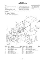
... 7 EXPLODED VIEWS NOTE: • -XX and -X mean standardized parts, so they are critical for routine service. Some delay should be anticipated when ordering these items. • The mechanical parts with part number specified. #1 15 13 10 1 14 15 12 not supplied 10 10 6 5 4 not supplied 11 9 10 7 8 17 3 2 RM-MD515 #1 Ref. or dotted line with mark ! No...
... 7 EXPLODED VIEWS NOTE: • -XX and -X mean standardized parts, so they are critical for routine service. Some delay should be anticipated when ordering these items. • The mechanical parts with part number specified. #1 15 13 10 1 14 15 12 not supplied 10 10 6 5 4 not supplied 11 9 10 7 8 17 3 2 RM-MD515 #1 Ref. or dotted line with mark ! No...

Service Manual
Page 100
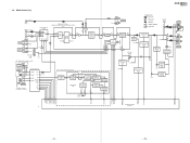
... CNIN DIGITAL CLV CPU INTERFACE TIMING LOGIC CLOCK GENERATOR BUFFER LOUT2 LOUT1 XRST MON MDP MDS LOCK XROF SQSO SQCK SENS DATA CLOK XLAT SCOR EXCK SBSO SPOD CKO XTAI XTAO C4M OPTICAL PICK-UP (KSS-213BA/F-NP) LASER DIODE PD LD 41 F 42 E I-V AMP FOCUS ERROR AMP FEO 1 FE BIAS 40 TRACKING ERROR TEO 45 AMP AUTOMATIC POWER CONTROL...
... CNIN DIGITAL CLV CPU INTERFACE TIMING LOGIC CLOCK GENERATOR BUFFER LOUT2 LOUT1 XRST MON MDP MDS LOCK XROF SQSO SQCK SENS DATA CLOK XLAT SCOR EXCK SBSO SPOD CKO XTAI XTAO C4M OPTICAL PICK-UP (KSS-213BA/F-NP) LASER DIODE PD LD 41 F 42 E I-V AMP FOCUS ERROR AMP FEO 1 FE BIAS 40 TRACKING ERROR TEO 45 AMP AUTOMATIC POWER CONTROL...
Service Manual
Page 103
HCD-MD515 RM-MD515 1-4. MAIN Section (2/2) MD REC-L G (Page 7) (Page 4) CD PLAY-L A (Page 7) MD PLAY-L H J100 (1/2) L TAPE IN R R-CH L GAME/ VIDEO IN R R-CH ATTENUATOR (-5dB) Q110 FUNCTION SWITCH IC100 1 2 4 3 5 INH A B 6 10 9 Q114 R-CH INPUT SELECT SWITCH, GRAPHIC EQUALIZER CONTROL, ELECTRICAL VOLUME IC111 IN 2B 69 IN 2A 71 INPUT SELECT R-CH SOUND CONTROL CIRCUIT KEY IN1 65 KEY OUT2 64 R-CH R-CH L J100 (2/2) TAPE OUT R 60 61 REC REC C2 A2...
HCD-MD515 RM-MD515 1-4. MAIN Section (2/2) MD REC-L G (Page 7) (Page 4) CD PLAY-L A (Page 7) MD PLAY-L H J100 (1/2) L TAPE IN R R-CH L GAME/ VIDEO IN R R-CH ATTENUATOR (-5dB) Q110 FUNCTION SWITCH IC100 1 2 4 3 5 INH A B 6 10 9 Q114 R-CH INPUT SELECT SWITCH, GRAPHIC EQUALIZER CONTROL, ELECTRICAL VOLUME IC111 IN 2B 69 IN 2A 71 INPUT SELECT R-CH SOUND CONTROL CIRCUIT KEY IN1 65 KEY OUT2 64 R-CH R-CH L J100 (2/2) TAPE OUT R 60 61 REC REC C2 A2...


