Operating Instructions (primary manual)
Page 3
... energy and, if not installed and used in a particular installation. Consult the dealer or an experienced radio/TV technician for a Class B digital device, pursuant to Part 15 of the following measures: - Note: This equipment has been tested and found to comply with the instructions, may cause harmful interference to radio communications.
... energy and, if not installed and used in a particular installation. Consult the dealer or an experienced radio/TV technician for a Class B digital device, pursuant to Part 15 of the following measures: - Note: This equipment has been tested and found to comply with the instructions, may cause harmful interference to radio communications.
Operating Instructions (primary manual)
Page 5
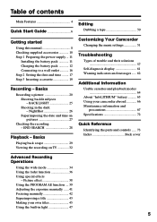
... Focusing manually 42 Superimposing a title 43 Making your camcorder abroad 66 Maintenance information and precautions 67 Specifications 72 Quick Reference Identifying the parts and controls ...... 73 Index Back cover Advanced Recording Operations Using the wide mode 34 Using the fader function 36 Using special effects - BACK LIGHT 25 Shooting in light 47... the battery pack 11 Charging the battery pack 12 Connecting to a wall outlet 16 Step 2 Setting the date and time ........ 17 Step 3 Inserting a cassette 19 Recording - Basics Playing back a tape 29 Viewing the...
... Focusing manually 42 Superimposing a title 43 Making your camcorder abroad 66 Maintenance information and precautions 67 Specifications 72 Quick Reference Identifying the parts and controls ...... 73 Index Back cover Advanced Recording Operations Using the wide mode 34 Using the fader function 36 Using special effects - BACK LIGHT 25 Shooting in light 47... the battery pack 11 Charging the battery pack 12 Connecting to a wall outlet 16 Step 2 Setting the date and time ........ 17 Step 3 Inserting a cassette 19 Recording - Basics Playing back a tape 29 Viewing the...

Operating Instructions (primary manual)
Page 13
.../F950 NP-F960 Full charge 150 210 300 390 420 Approximate number of the AC power adaptor. The battery pack is wrong with the metal parts of the DC plug of minutes to be used for a long time, charge the battery pack fully, and then use it until it fully discharges...
.../F950 NP-F960 Full charge 150 210 300 390 420 Approximate number of the AC power adaptor. The battery pack is wrong with the metal parts of the DC plug of minutes to be used for a long time, charge the battery pack fully, and then use it until it fully discharges...
Operating Instructions (primary manual)
Page 19
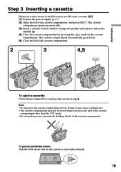
...Close the lid of the cassette compartment. 2 3 EJECT 4,5 To eject a cassette Follow the procedure above, and eject the cassette in the Hi8 system, use Hi8 video cassettes . (1) Prepare the power supply (p. 11). (2) Open the lid of the cassette compartment. To prevent accidental erasure Slide the write-protect...write-protect tab on the cassette up your camcorder by pressing the mark on the cassette to record in step 3. Getting started Step 3 Inserting a cassette When you press any part of the cassette compartment other than the mark. • Do not pick up . (4) Close...
...Close the lid of the cassette compartment. 2 3 EJECT 4,5 To eject a cassette Follow the procedure above, and eject the cassette in the Hi8 system, use Hi8 video cassettes . (1) Prepare the power supply (p. 11). (2) Open the lid of the cassette compartment. To prevent accidental erasure Slide the write-protect...write-protect tab on the cassette up your camcorder by pressing the mark on the cassette to record in step 3. Getting started Step 3 Inserting a cassette When you press any part of the cassette compartment other than the mark. • Do not pick up . (4) Close...

Operating Instructions (primary manual)
Page 46
Set the POWER switch to CAMERA again, then proceed from step 1. We recommend setting the POWER switch to PLAYER or removing the cassette so that your camcorder does not automatically turn ... you select [ ] The menu for selecting alphabet and Russian characters appears. Enter the new title as desired. To enter a space Select [ Z& ? ! ], then select the blank part. 46 If you take 5 minutes or longer to change a title you have entered remain stored in memory. The last character is in your camcorder The...
Set the POWER switch to CAMERA again, then proceed from step 1. We recommend setting the POWER switch to PLAYER or removing the cassette so that your camcorder does not automatically turn ... you select [ ] The menu for selecting alphabet and Russian characters appears. Enter the new title as desired. To enter a space Select [ Z& ? ! ], then select the blank part. 46 If you take 5 minutes or longer to change a title you have entered remain stored in memory. The last character is in your camcorder The...
Operating Instructions (primary manual)
Page 70
..., and periodically turn on the power, operate the CAMERA and PLAYER sections and play back a tape for ...pull the power cord itself. •Do not operate the unit with the metal parts of the connecting section. This will damage the cord and may cause fire or ...cause a fire or damage the built-in light. AM receivers and video equipment disturb AM reception and video operation. •The unit becomes warm during charging, keep it out...camcorder is not to sense the type and thickness of the tape and if the recording tab is in or out. Vibrating 70 These holes are : - When you are...
..., and periodically turn on the power, operate the CAMERA and PLAYER sections and play back a tape for ...pull the power cord itself. •Do not operate the unit with the metal parts of the connecting section. This will damage the cord and may cause fire or ...cause a fire or damage the built-in light. AM receivers and video equipment disturb AM reception and video operation. •The unit becomes warm during charging, keep it out...camcorder is not to sense the type and thickness of the tape and if the recording tab is in or out. Vibrating 70 These holes are : - When you are...
Operating Instructions (primary manual)
Page 72
Specifications Video camera recorder Output connectors S video output Storage temperature -20 °C to +60 °C (-4 °F to +140 °F) Dimensions (approx.) 4-pin mini DIN 104 × 109 × 223 mm System Video recording system 2 rotary heads Helical scanning FM system Audio recording system Rotary heads, FM system Video signal NTSC color, EIA standards Usable cassette 8mm video format cassette Hi8 or...
Specifications Video camera recorder Output connectors S video output Storage temperature -20 °C to +60 °C (-4 °F to +140 °F) Dimensions (approx.) 4-pin mini DIN 104 × 109 × 223 mm System Video recording system 2 rotary heads Helical scanning FM system Audio recording system Rotary heads, FM system Video signal NTSC color, EIA standards Usable cassette 8mm video format cassette Hi8 or...

Operating Instructions (primary manual)
Page 73
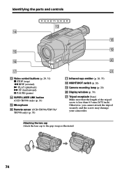
Identifying the parts and controls Camcorder 1 2 7 3 8 9 4 0 5 qa 6 qs 1 Eyecup (p. 69) 2 Viewfinder lens adjustment lever (p. 24) 3 Eyecup RELEASE knob (p. 69) 4 v (earphone) jack When you purchase accessories with this ... 6 SEL/PUSH EXEC dial (p. 35, 51) 7 Power zoom lever (p. 23) 8 BATT RELEASE lever (p. 11) 9 POWER switch (p. 20) q; Quick Reference 73 When purchasing Sony video products, Sony recommends that this "GENUINE VIDEO ACCESSORIES" mark. START/STOP button (p. 20) qa Hooks for shoulder strap (p. 75) qs DC IN jack (p. 12, 16) This mark indicates that you...
Identifying the parts and controls Camcorder 1 2 7 3 8 9 4 0 5 qa 6 qs 1 Eyecup (p. 69) 2 Viewfinder lens adjustment lever (p. 24) 3 Eyecup RELEASE knob (p. 69) 4 v (earphone) jack When you purchase accessories with this ... 6 SEL/PUSH EXEC dial (p. 35, 51) 7 Power zoom lever (p. 23) 8 BATT RELEASE lever (p. 11) 9 POWER switch (p. 20) q; Quick Reference 73 When purchasing Sony video products, Sony recommends that this "GENUINE VIDEO ACCESSORIES" mark. START/STOP button (p. 20) qa Hooks for shoulder strap (p. 75) qs DC IN jack (p. 12, 16) This mark indicates that you...
Operating Instructions (primary manual)
Page 74
... your camcorder. qj qd Video control buttons (p. 29, 31) x STOP (stop) m REW (rewind) N PLAY (playback) M FF (fastforward) X PAUSE (pause) qf SUPER LASER LINK button (CCD-TRV98 only) (p. 33) qg Microphone qh Remote sensor (CCD-TRV49/TRV78/ TRV98 only) (p. 78) wa qj Infrared rays emitter (p. 26, 33) qk NIGHTSHOT switch (p. 26) ql Camera recording lamp (p. 20) w; Attaching the...
... your camcorder. qj qd Video control buttons (p. 29, 31) x STOP (stop) m REW (rewind) N PLAY (playback) M FF (fastforward) X PAUSE (pause) qf SUPER LASER LINK button (CCD-TRV98 only) (p. 33) qg Microphone qh Remote sensor (CCD-TRV49/TRV78/ TRV98 only) (p. 78) wa qj Infrared rays emitter (p. 26, 33) qk NIGHTSHOT switch (p. 26) ql Camera recording lamp (p. 20) w; Attaching the...
Operating Instructions (primary manual)
Page 75
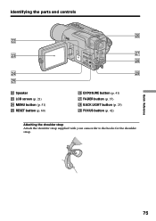
Identifying the parts and controls ws wd wf wg ws Speaker wd LCD screen (p. 21) wf MENU button (p. 51) wg RESET button (p. 60) wh wj wk wl wh EXPOSURE button (p. 41) wj FADER button (p. 37) wk BACK LIGHT button (p. 25) wl FOCUS button (p. 42) Attaching the shoulder strap Attach the shoulder strap supplied with your camcorder to the hooks for the shoulder strap. Quick Reference 75
Identifying the parts and controls ws wd wf wg ws Speaker wd LCD screen (p. 21) wf MENU button (p. 51) wg RESET button (p. 60) wh wj wk wl wh EXPOSURE button (p. 41) wj FADER button (p. 37) wk BACK LIGHT button (p. 25) wl FOCUS button (p. 42) Attaching the shoulder strap Attach the shoulder strap supplied with your camcorder to the hooks for the shoulder strap. Quick Reference 75

Operating Instructions (primary manual)
Page 76
Identifying the parts and controls ef eg eh e; DATE button (p. 27) ea DISPLAY button (p. 30) es TITLE button (p. 43) ed VOLUME buttons (p. 29) ef LIGHT button (p. 47) eg TIME button (p. 27) eh Viewfinder (p. 24) ej COUNTER RESET button (p. 21) ek CHG lamp (p. 12) el END SEARCH button (p. 28) 76 ej ea ek es ed el e;
Identifying the parts and controls ef eg eh e; DATE button (p. 27) ea DISPLAY button (p. 30) es TITLE button (p. 43) ed VOLUME buttons (p. 29) ef LIGHT button (p. 47) eg TIME button (p. 27) eh Viewfinder (p. 24) ej COUNTER RESET button (p. 21) ek CHG lamp (p. 12) el END SEARCH button (p. 28) 76 ej ea ek es ed el e;
Operating Instructions (primary manual)
Page 77
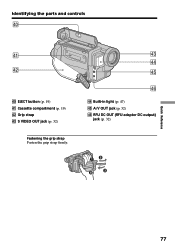
Identifying the parts and controls r; ra rs r; EJECT button (p. 19) ra Cassette compartment (p. 19) rs Grip strap rd S VIDEO OUT jack (p. 32) Fastening the grip strap Fasten the grip strap firmly. rd rf rg rh rf Built-in light (p. 47) rg A/V OUT jack (p. 32) rh RFU DC OUT (RFU adaptor DC output) jack (p. 32) Quick Reference 77
Identifying the parts and controls r; ra rs r; EJECT button (p. 19) ra Cassette compartment (p. 19) rs Grip strap rd S VIDEO OUT jack (p. 32) Fastening the grip strap Fasten the grip strap firmly. rd rf rg rh rf Built-in light (p. 47) rg A/V OUT jack (p. 32) rh RFU DC OUT (RFU adaptor DC output) jack (p. 32) Quick Reference 77
Operating Instructions (primary manual)
Page 78
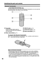
Notes on your camcorder. 1 4 2 5 3 1 Transmitter Point toward the remote sensor to the + - CCD-TRV49/TRV78/TRV98 only The buttons that have the same name on the Remote Commander as direct sunlight or overhead lighting. polarities on the batteries to control ... another Sony VCR in the commander mode VTR 2. Otherwise, the Remote Commander may not function properly. •Your camcorder works in the commander mode VTR 2, we recommend changing the commander mode or covering the sensor of the VCR with black paper. 78 marks inside the battery compartment. Identifying the parts and...
Notes on your camcorder. 1 4 2 5 3 1 Transmitter Point toward the remote sensor to the + - CCD-TRV49/TRV78/TRV98 only The buttons that have the same name on the Remote Commander as direct sunlight or overhead lighting. polarities on the batteries to control ... another Sony VCR in the commander mode VTR 2. Otherwise, the Remote Commander may not function properly. •Your camcorder works in the commander mode VTR 2, we recommend changing the commander mode or covering the sensor of the VCR with black paper. 78 marks inside the battery compartment. Identifying the parts and...
Operating Instructions (primary manual)
Page 79
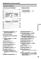
...CCD- TRV68/TRV78/TRV88/TRV98 only) (p. 52) qs Manual focusing indicator (p. 42) qd Built-in the viewfinder only wd Date or time indicator (p. 18, 27)/Tape counter indicator (p. 25)/Self-diagnosis display indicator (p. 61) 79 Time indicator (p. 18, 27) wa Warning indicators (p. 62) ws Recording... 2 Hi8 format indicator 3 Remaining battery time indicator (p. 25) 4 Exposure indicator (p. 41)/Zoom indicator (p. 23) 5 Fader indicator (p. 36) 6 Wide mode indicator (p. 34) 7 Picture effect indicator (p. 38) 8 Volume indicator (p. 29) 9 PROGRAM AE indicator (p. 40) q; Identifying the parts and ...
...CCD- TRV68/TRV78/TRV88/TRV98 only) (p. 52) qs Manual focusing indicator (p. 42) qd Built-in the viewfinder only wd Date or time indicator (p. 18, 27)/Tape counter indicator (p. 25)/Self-diagnosis display indicator (p. 61) 79 Time indicator (p. 18, 27) wa Warning indicators (p. 62) ws Recording... 2 Hi8 format indicator 3 Remaining battery time indicator (p. 25) 4 Exposure indicator (p. 41)/Zoom indicator (p. 23) 5 Fader indicator (p. 36) 6 Wide mode indicator (p. 34) 7 Picture effect indicator (p. 38) 8 Volume indicator (p. 29) 9 PROGRAM AE indicator (p. 40) q; Identifying the parts and ...


