
Service Manual
Page 12
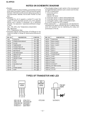
... and performance of the set . NO SW720 SW721 SW722 SW723 SW724 SW725 SW726 SW727 SW728 SWB101 SWB102 SWB103 SWB104 SWB105 SWB106 SWB107 SWB108 DESCRIPTION VIDEO/AUX DISC 3 EJECT DISC 2 EJECT DISC 1 EJECT DISC 1 DISC 2 DISC 3 EQUALIZER X-BASS/DEMO CAM 1 CAM 2 CAM 3 CAM 4... EC B (S) (G) (D) (1) (2) (3) KRC102 M KTA1274 Y KRC104 M KTC3199 GR KTA1266 GR KTC3194 Y KTA1271 Y KTC3203 Y KTA1273 Y 2SC1845 F BC E KTC2026 - 12 - XL-HP500 NOTES ON SCHEMATIC DIAGRAM • Resistor: To differentiate the units of P.W.Board for this symbol P means pico-farad and the unit of the capacitor without...
... and performance of the set . NO SW720 SW721 SW722 SW723 SW724 SW725 SW726 SW727 SW728 SWB101 SWB102 SWB103 SWB104 SWB105 SWB106 SWB107 SWB108 DESCRIPTION VIDEO/AUX DISC 3 EJECT DISC 2 EJECT DISC 1 EJECT DISC 1 DISC 2 DISC 3 EQUALIZER X-BASS/DEMO CAM 1 CAM 2 CAM 3 CAM 4... EC B (S) (G) (D) (1) (2) (3) KRC102 M KTA1274 Y KRC104 M KTC3199 GR KTA1266 GR KTC3194 Y KTA1271 Y KTC3203 Y KTA1273 Y 2SC1845 F BC E KTC2026 - 12 - XL-HP500 NOTES ON SCHEMATIC DIAGRAM • Resistor: To differentiate the units of P.W.Board for this symbol P means pico-farad and the unit of the capacitor without...
Service Manual
Page 14
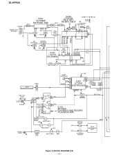
... 15 16 11 3 4 5 6 PLL(TUNER) OSC 17 +B5 7 9 10 21 +B5 FM+B Q360 FM SWITCHING CNP9 FROM CD SECTION BI901 8 7 6 +B5 JK690 VIDEO/AUX 23 L AUX L 9 DI 1 R R 16 CE 2 TAPE TUNER L 10 IC601 CLK R 15 L 11 LC75341 R14 AUDIO PROCESSOR 24 -20dB ATT Q601 21 R Q602 Q603 Q604 CD L ... SWITCHING Q110 BIAS BIAS MOTOR DRIVER +B3 Q500 TAPE MECHANISM ASS'Y +B3 Q501 C SOLENOID DRIVER VF1 -VF Figure 14 BLOCK DIAGRAM (2/3) - 14 - XL-HP500 CNP302 FM/AM LOOP 1 ANTENNA 2 3 IC303 +B6 +B5 IC301 LA1832S B.P.F BF301 TA7358AP FM FRONT END 1 34 6 9 57 8 FM IF DET.
... 15 16 11 3 4 5 6 PLL(TUNER) OSC 17 +B5 7 9 10 21 +B5 FM+B Q360 FM SWITCHING CNP9 FROM CD SECTION BI901 8 7 6 +B5 JK690 VIDEO/AUX 23 L AUX L 9 DI 1 R R 16 CE 2 TAPE TUNER L 10 IC601 CLK R 15 L 11 LC75341 R14 AUDIO PROCESSOR 24 -20dB ATT Q601 21 R Q602 Q603 Q604 CD L ... SWITCHING Q110 BIAS BIAS MOTOR DRIVER +B3 Q500 TAPE MECHANISM ASS'Y +B3 Q501 C SOLENOID DRIVER VF1 -VF Figure 14 BLOCK DIAGRAM (2/3) - 14 - XL-HP500 CNP302 FM/AM LOOP 1 ANTENNA 2 3 IC303 +B6 +B5 IC301 LA1832S B.P.F BF301 TA7358AP FM FRONT END 1 34 6 9 57 8 FM IF DET.

Service Manual
Page 18
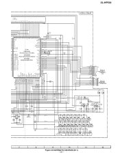
...CD_D_GND 15 Q603 KTC3199 GR Q604 KTC3199 GR C640 22/50 R620 22K R621 22K C639 2.2/50 R609 10K C625 100P FM SIGNAL CD SIGNAL AUX SIGNAL PLAYBACK SIGNAL RECORD SIGNAL R617 2.2K C637 0.001 C638 0.001 R616 2.2K R615 3.3K Q601 KTC3199 GR R613 390 R611 2.2K ... V 4 LOUT R -+ 5 LBASS RB LTRE 6 -+ R 7 LIN - + - + - + C615 4.7/50 8 LSEL0 RS -+ C617 1/50 9 L4 AUX C631 0.0047 C619 1/50 10 L3 C621 1/50 11 L2 DECK TUNER 12 L1 CD C623 1/50 TO MAIN PWB(1/3) P16 1 - XL-HP500 A MAIN PWB-A1(2/3) B TO MAIN PWB(1/3) P16 1 - F~G C134 220/10 E F TAPE MECHANISM Ass'y(210) RECORD...
...CD_D_GND 15 Q603 KTC3199 GR Q604 KTC3199 GR C640 22/50 R620 22K R621 22K C639 2.2/50 R609 10K C625 100P FM SIGNAL CD SIGNAL AUX SIGNAL PLAYBACK SIGNAL RECORD SIGNAL R617 2.2K C637 0.001 C638 0.001 R616 2.2K R615 3.3K Q601 KTC3199 GR R613 390 R611 2.2K ... V 4 LOUT R -+ 5 LBASS RB LTRE 6 -+ R 7 LIN - + - + - + C615 4.7/50 8 LSEL0 RS -+ C617 1/50 9 L4 AUX C631 0.0047 C619 1/50 10 L3 C621 1/50 11 L2 DECK TUNER 12 L1 CD C623 1/50 TO MAIN PWB(1/3) P16 1 - XL-HP500 A MAIN PWB-A1(2/3) B TO MAIN PWB(1/3) P16 1 - F~G C134 220/10 E F TAPE MECHANISM Ass'y(210) RECORD...
Service Manual
Page 23
... 1K 1.5K 2.2K 2.7K 3.9K 5.6K SW713 SW714 SW715 SW716 SW717 SW718 SW719 SW720 PRESET PRESET PLAY REVERSE STOP PLAY CD TUNER (BAND) TAPE VIDEO /AUX RD01 RD02 RD03 RD04 RD05 RD06 RD07 680 820 1K 1.5K 2.2K SW701 SW702 SW703 SW704 SW705 2.7K SW706 3.9K SW707 SW708 POWER ON/STAND... 33 32 31 1K 0.022 KEY 0 KEY 1 KEY 2 1K 1K 1K 560 2.2K 680 680 1K R790 5.6K R793 10K R721 C705 R794 10K R795 1.5 XL-HP500 DISPLAY PWB-A2 CNP5A CD RESOUT 7 CD_CLK 6 CD_DI 5 CD_DO 4 CD_CE 3 CD_DRF 2 CD_WRQ 1 BI706 VF2 1 2 -VF 3 P_IN 4 VF1 5 AC_RLY CON 6 7 FC5 P25...
... 1K 1.5K 2.2K 2.7K 3.9K 5.6K SW713 SW714 SW715 SW716 SW717 SW718 SW719 SW720 PRESET PRESET PLAY REVERSE STOP PLAY CD TUNER (BAND) TAPE VIDEO /AUX RD01 RD02 RD03 RD04 RD05 RD06 RD07 680 820 1K 1.5K 2.2K SW701 SW702 SW703 SW704 SW705 2.7K SW706 3.9K SW707 SW708 POWER ON/STAND... 33 32 31 1K 0.022 KEY 0 KEY 1 KEY 2 1K 1K 1K 560 2.2K 680 680 1K R790 5.6K R793 10K R721 C705 R794 10K R795 1.5 XL-HP500 DISPLAY PWB-A2 CNP5A CD RESOUT 7 CD_CLK 6 CD_DI 5 CD_DO 4 CD_CE 3 CD_DRF 2 CD_WRQ 1 BI706 VF2 1 2 -VF 3 P_IN 4 VF1 5 AC_RLY CON 6 7 FC5 P25...
Service Manual
Page 28
XL-HP500 A TO CD SERVO PWB P30 3 - B CNP5 FC5 DISC 7 1 SELECT B SW723 B C E Q701 DISPLAY PWB-A2 RD22 1 12 5 6 7 8 9 10 11 12 13 14 15 16 17 18 ... ECB R506 R714 R715 R720 R721 R716 R732 VR701 VOLUME R789 R723 R727 R729 C705 R724 SW712 PRESET 7 RD11 SW713 PRESET 30 31 SW720 VIDEO /AUX RD18 R726 R725 SW719 RD12 TAPE SW714 PLAY R RD SW70 M COLOR TABLE F B R BROWN FC702 RD WH GY WH GY RD( R) RED 1 2 345 1 1 OR ORANGE CNS706...
XL-HP500 A TO CD SERVO PWB P30 3 - B CNP5 FC5 DISC 7 1 SELECT B SW723 B C E Q701 DISPLAY PWB-A2 RD22 1 12 5 6 7 8 9 10 11 12 13 14 15 16 17 18 ... ECB R506 R714 R715 R720 R721 R716 R732 VR701 VOLUME R789 R723 R727 R729 C705 R724 SW712 PRESET 7 RD11 SW713 PRESET 30 31 SW720 VIDEO /AUX RD18 R726 R725 SW719 RD12 TAPE SW714 PLAY R RD SW70 M COLOR TABLE F B R BROWN FC702 RD WH GY WH GY RD( R) RED 1 2 345 1 1 OR ORANGE CNS706...
Service Manual
Page 29
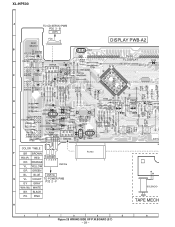
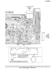
D TAPE MECHANISM SOLENOID PWB Ass'y(210-3) TAPE MECHANISM Ass'y(210) TAPE MOTOR (210-2) 7 8 9 10 11 12 Figure 29 WIRING SIDE OF P.W.BOARD (4/7) - 29 - XL-HP500 TO CD SERVO PWB P30 4 - E CNP6 LAY PWB-A2 C707 FL701 29 30 31 32 33 34 35 36 37 38 39 40 41 44 ... R748 R745 R787 SW703 R746 R744 SW702 RD05 SW704 SW705 R784 SW717 CD R794 TUNNING/TIME 2 4 6 8 1 3 5 7 10 12 14 9 11 13 16 15 SW720 VIDEO /AUX RD18 R726 RD17 SW708 SW707 RD06 RD07 SW706 MEMORY /SET REVERSE MODE REC/PAUSE CNP701A R783 TIMER/ SLEEP CLOCK SW701 POWER ON/ STAND-BY 1 FC701...
D TAPE MECHANISM SOLENOID PWB Ass'y(210-3) TAPE MECHANISM Ass'y(210) TAPE MOTOR (210-2) 7 8 9 10 11 12 Figure 29 WIRING SIDE OF P.W.BOARD (4/7) - 29 - XL-HP500 TO CD SERVO PWB P30 4 - E CNP6 LAY PWB-A2 C707 FL701 29 30 31 32 33 34 35 36 37 38 39 40 41 44 ... R748 R745 R787 SW703 R746 R744 SW702 RD05 SW704 SW705 R784 SW717 CD R794 TUNNING/TIME 2 4 6 8 1 3 5 7 10 12 14 9 11 13 16 15 SW720 VIDEO /AUX RD18 R726 RD17 SW708 SW707 RD06 RD07 SW706 MEMORY /SET REVERSE MODE REC/PAUSE CNP701A R783 TIMER/ SLEEP CLOCK SW701 POWER ON/ STAND-BY 1 FC701...
Service Manual
Page 51
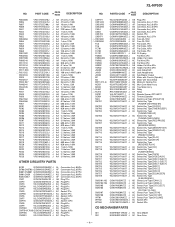
...AB Flat Wire,3Pin AB Holder,Flat Wire,5Pin AB Holder,Flat Wire,3Pin AC Jack,Video/AUX AK Jack,Headphones AD Sub Woofer Output AS Motor with Chassis [Spindle] AP Motor with Gear... Type [CD] AC Switch,Key Type [TUNER (BAND)] AC Switch,Key Type [TAPE] AC Switch,Key Type [VIDEO/AUX] AC Switch,Key Type [DISC 3 EJECT] AC Switch,Key Type [DISC 2 EJECT] AC Switch,Key Type [DISC ...Socket,3Pin CD MECHANISM PARTS 301 NGERH0011AWZZ J AC Gear,Middle 302 NGERH0012AWZZ J AC Gear,Drive - 4 - XL-HP500 NO. PART CODE PRICE RANK DESCRIPTION R804,805 R806 R807 R808 R841 R842 R843 R852 R853,854 R856 R857...
...AB Flat Wire,3Pin AB Holder,Flat Wire,5Pin AB Holder,Flat Wire,3Pin AC Jack,Video/AUX AK Jack,Headphones AD Sub Woofer Output AS Motor with Chassis [Spindle] AP Motor with Gear... Type [CD] AC Switch,Key Type [TUNER (BAND)] AC Switch,Key Type [TAPE] AC Switch,Key Type [VIDEO/AUX] AC Switch,Key Type [DISC 3 EJECT] AC Switch,Key Type [DISC 2 EJECT] AC Switch,Key Type [DISC ...Socket,3Pin CD MECHANISM PARTS 301 NGERH0011AWZZ J AC Gear,Middle 302 NGERH0012AWZZ J AC Gear,Drive - 4 - XL-HP500 NO. PART CODE PRICE RANK DESCRIPTION R804,805 R806 R807 R808 R841 R842 R843 R852 R853,854 R856 R857...
Operation Manual
Page 22
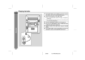
... 6 Turn the MIC LEVEL control towards MAX to increase the microphone volume and towards MIN to the MIC socket. ! Karaoke E-21 02/8/6 XL-HP500W(A)3.fm XL-HP500W Playing karaoke ENGLISH 1 Set the MIC LEVEL control to MIN to protect the speakers from shock noise and to avoid disturbing noises. 2 ... with a 3.5 mm (1/8") diameter plug. 3 Press the ON/STAND-BY button to turn the power on. 4 Press the CD, TUNER (BAND), TAPE or VIDEO/AUX button to select the audio source and play it. 5 Adjust the volume of the audio source using a microphone with a 6.3 mm (1/4") plug, an impedance of 600...
... 6 Turn the MIC LEVEL control towards MAX to increase the microphone volume and towards MIN to the MIC socket. ! Karaoke E-21 02/8/6 XL-HP500W(A)3.fm XL-HP500W Playing karaoke ENGLISH 1 Set the MIC LEVEL control to MIN to protect the speakers from shock noise and to avoid disturbing noises. 2 ... with a 3.5 mm (1/8") diameter plug. 3 Press the ON/STAND-BY button to turn the power on. 4 Press the CD, TUNER (BAND), TAPE or VIDEO/AUX button to select the audio source and play it. 5 Adjust the volume of the audio source using a microphone with a 6.3 mm (1/4") plug, an impedance of 600...
Operation Manual
Page 23
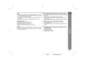
... steps 3 - 7 above. If this happens, lower the microphone volume. ! Notes: ! Move the microphone away from the MIC socket. ! Karaoke 02/8/6 XL-HP500W(A)3.fm E-22 Reduce the microphone volume. ! Caution: ! ENGLISH " Recording of mixed sound to a cassette tape You can record mixed sound from the microphone... and CD, TUNER or VIDEO/AUX. 1 Perform steps 1 - 3 in "Playing karaoke" on side A, or the button for vocal use. If squealing occurs: ! Reduce the volume of ...
... steps 3 - 7 above. If this happens, lower the microphone volume. ! Notes: ! Move the microphone away from the MIC socket. ! Karaoke 02/8/6 XL-HP500W(A)3.fm E-22 Reduce the microphone volume. ! Caution: ! ENGLISH " Recording of mixed sound to a cassette tape You can record mixed sound from the microphone... and CD, TUNER or VIDEO/AUX. 1 Perform steps 1 - 3 in "Playing karaoke" on side A, or the button for vocal use. If squealing occurs: ! Reduce the volume of ...
Operation Manual
Page 27
The unit will enter the stand-by mode. 02/8/6 XL-HP500W(A)3.fm E-26 XL-HP500W ENGLISH Notes: ! It will enter the power stand-by mode automatically. In timer playback: If you were listening at before your system enters the ... until a new time is reached in timer recording or 1 hour after the playback starts in step 2. However, another unit connected to the VIDEO/AUX sockets, select "VIDEO/AUX" in timer playback. If you select TUNER, it reaches the volume you select CD or TAPE, the unit will enter the standby mode one...
The unit will enter the stand-by mode. 02/8/6 XL-HP500W(A)3.fm E-26 XL-HP500W ENGLISH Notes: ! It will enter the power stand-by mode automatically. In timer playback: If you were listening at before your system enters the ... until a new time is reached in timer recording or 1 hour after the playback starts in step 2. However, another unit connected to the VIDEO/AUX sockets, select "VIDEO/AUX" in timer playback. If you select TUNER, it reaches the volume you select CD or TAPE, the unit will enter the standby mode one...
Operation Manual
Page 28
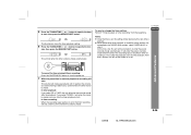
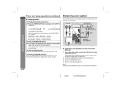
.... 4 Your system will be turned down 1 minute before the sleep operation finishes. to turn the power on. 3 Press the VIDEO/AUX button. 4 Play the connected equipment. XL-HP500W Timer and sleep operation (continued) ENGLISH " Sleep operation 1 Play back the desired sound source. 2 Press the TIMER/SLEEP button ...Note: To prevent hum interference, place this unit and the video output to a television. 2 Press the ON/STAND-BY button to the VIDEO/AUX sockets. Advanced Features To change the sleep time: Whilst the sleep time is not included. To cancel the sleep operation: Press the ON/STAND-...
.... 4 Your system will be turned down 1 minute before the sleep operation finishes. to turn the power on. 3 Press the VIDEO/AUX button. 4 Play the connected equipment. XL-HP500W Timer and sleep operation (continued) ENGLISH " Sleep operation 1 Play back the desired sound source. 2 Press the TIMER/SLEEP button ...Note: To prevent hum interference, place this unit and the video output to a television. 2 Press the ON/STAND-BY button to the VIDEO/AUX sockets. Advanced Features To change the sleep time: Whilst the sleep time is not included. To cancel the sleep operation: Press the ON/STAND-...
Operation Manual
Page 29
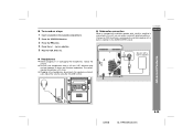
... unplugging the headphones, reduce the volume. ! Connect an RCA lead from a commercially available speaker with a built-in the cassette compartment. 2 Press the VIDEO/AUX button. 3 Press the button. 4 Press the / ( ) or button. 5 Play the VCR, DVD, etc. " Headphones ! Be sure your headphones... ohms and 50 ohms impedance. " To record on a tape 1 Insert a cassette in amplifier Advanced Features 02/8/6 XL-HP500W(A)3.fm E-28 The recommended impedance is connected to the SUBWOOFER socket. XL-HP500W " Subwoofer connection When a commercially available speaker with emphasised bass.
... unplugging the headphones, reduce the volume. ! Connect an RCA lead from a commercially available speaker with a built-in the cassette compartment. 2 Press the VIDEO/AUX button. 3 Press the button. 4 Press the / ( ) or button. 5 Play the VCR, DVD, etc. " Headphones ! Be sure your headphones... ohms and 50 ohms impedance. " To record on a tape 1 Insert a cassette in amplifier Advanced Features 02/8/6 XL-HP500W(A)3.fm E-28 The recommended impedance is connected to the SUBWOOFER socket. XL-HP500W " Subwoofer connection When a commercially available speaker with emphasised bass.


