Service Manual
Page 7
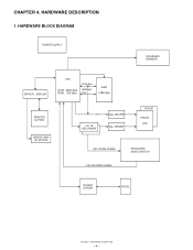
CHAPTER 4. DRIVER , SENSOR CPU ROM : 256K Byte RAM : 20K Byte Data bus Address bus RAM 128K Byte PRINTER M-T53II PAPER TAKE UP MOTOR 4 to 16 DECORDER Seg. DRIVER Dig. DRIVER POPUP FRONT LED KEY SCAN SIGNAL KEYBOARD MODE SWITCH KEY RETURN SIGNAL RS232C DRIVER RS232 XE-A202U HARDWARE DESCRIPTION - 6 - HARDWARE DESCRIPTION 1. HARDWARE BLOCK DIAGRAM POWER SUPPLY STANDARD DRAWER.
CHAPTER 4. DRIVER , SENSOR CPU ROM : 256K Byte RAM : 20K Byte Data bus Address bus RAM 128K Byte PRINTER M-T53II PAPER TAKE UP MOTOR 4 to 16 DECORDER Seg. DRIVER Dig. DRIVER POPUP FRONT LED KEY SCAN SIGNAL KEYBOARD MODE SWITCH KEY RETURN SIGNAL RS232C DRIVER RS232 XE-A202U HARDWARE DESCRIPTION - 6 - HARDWARE DESCRIPTION 1. HARDWARE BLOCK DIAGRAM POWER SUPPLY STANDARD DRAWER.
Service Manual
Page 10
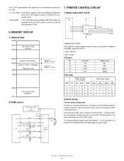
...) falls bellow the specified level, the P-OFF signal is driven to the shift register synchronizing with the CLOCK (CP) and stored in the figure, thermal head consists of heating elements and head drivers which drives and controls those heating elements. CPU port 76 P14 75 P15 74 P16.... VLED signal: If the LED/Logic power voltage VLED falls below the specified level, the P-OFF signal is driver to LOW by two comparators and sent to the print data. XE-A202U HARDWARE DESCRIPTION - 9 - MEMORY CIRCUIT 1) Address map 00000h 00400h 05400h CPU internal RAM 20kbytes 06000h 08000h...
...) falls bellow the specified level, the P-OFF signal is driven to the shift register synchronizing with the CLOCK (CP) and stored in the figure, thermal head consists of heating elements and head drivers which drives and controls those heating elements. CPU port 76 P14 75 P15 74 P16.... VLED signal: If the LED/Logic power voltage VLED falls below the specified level, the P-OFF signal is driver to LOW by two comparators and sent to the print data. XE-A202U HARDWARE DESCRIPTION - 9 - MEMORY CIRCUIT 1) Address map 00000h 00400h 05400h CPU internal RAM 20kbytes 06000h 08000h...


