
Service Manual
Page 1
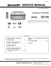
... to change without notice. The contents are important for maintaining the safety of the set . QT-V5 SERVICE MANUAL No. Be sure to those specified be restored to its original condition and only parts identical to replace these parts with " " are subject to be used . DIAGRAMS [1] Block diagrams 3-1 CHAPTER 4. CONTENTS CHAPTER 1. S7459QTV5//// DVD/CD SYSTEM MODEL QT-V5 In the interests of user-safety the set should be used...
... to change without notice. The contents are important for maintaining the safety of the set . QT-V5 SERVICE MANUAL No. Be sure to those specified be restored to its original condition and only parts identical to replace these parts with " " are subject to be used . DIAGRAMS [1] Block diagrams 3-1 CHAPTER 4. CONTENTS CHAPTER 1. S7459QTV5//// DVD/CD SYSTEM MODEL QT-V5 In the interests of user-safety the set should be used...

Service Manual
Page 2
... earth ground. * Use a VTVM or VOM with the AC line cord plug connection reversed. Inspect all protective devices such as conduit or electrical ground connected to the chassis (antenna, metal cabinet, screw heads, knobs and control shafts, escutcheon, etc.) and measure the AC voltage drop across the resistor (See diagram). * Connect the resistor connection to all exposed metal cabinet parts and a known...
... earth ground. * Use a VTVM or VOM with the AC line cord plug connection reversed. Inspect all protective devices such as conduit or electrical ground connected to the chassis (antenna, metal cabinet, screw heads, knobs and control shafts, escutcheon, etc.) and measure the AC voltage drop across the resistor (See diagram). * Connect the resistor connection to all exposed metal cabinet parts and a known...

Service Manual
Page 3
... TO THE OPERATION MANUAL. Power source Power consumption Output power Speakers Dimensions Weight Signal system Supported disc types Video signal Audio signal Audio output terminals Video output terminals Frequency range AC 120 V, 60 Hz DC 12 V ["D" size (UM/SUM-1, R20 or HP-2) battery 8] DC 3 V ["AA" size (UM/SUM-3, R6 or HP-7) battery 2 for memory battery] 25 W 3.5 watts minimum RMS per channel into 4 ohms from 150 Hz to change without prior notice. 1 - 1 QT-V5 QT-V5 For U.S.A. Linear PCM DVD: istics 20...
... TO THE OPERATION MANUAL. Power source Power consumption Output power Speakers Dimensions Weight Signal system Supported disc types Video signal Audio signal Audio output terminals Video output terminals Frequency range AC 120 V, 60 Hz DC 12 V ["D" size (UM/SUM-1, R20 or HP-2) battery 8] DC 3 V ["AA" size (UM/SUM-3, R6 or HP-7) battery 2 for memory battery] 25 W 3.5 watts minimum RMS per channel into 4 ohms from 150 Hz to change without prior notice. 1 - 1 QT-V5 QT-V5 For U.S.A. Linear PCM DVD: istics 20...
Service Manual
Page 4
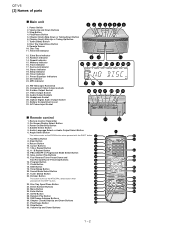
.... QT-V5 [2] Names of parts Main unit 1. Play/Pause Button 5. Disc Tray Open/Close Button 9. Extra Bass Indicator 13. Video Output Socket 28. Headphone Socket 30. Remote Control Transmitter 2. Clear Button 9. A - Fast Reverse/Tuner Preset Down and 8 25 Fast Forward/Tuner Preset Up Buttons 9 26 16. Chapter (Track) Skip Up and Down Buttons 31. Play/Pause Button 21 32. Track Indicator 17. Surround Indicator 18. CD Indicator 23. Audio Language Select or Audio Output Select Button 6. Top Menu Button 8. Timer...
.... QT-V5 [2] Names of parts Main unit 1. Play/Pause Button 5. Disc Tray Open/Close Button 9. Extra Bass Indicator 13. Video Output Socket 28. Headphone Socket 30. Remote Control Transmitter 2. Clear Button 9. A - Fast Reverse/Tuner Preset Down and 8 25 Fast Forward/Tuner Preset Up Buttons 9 26 16. Chapter (Track) Skip Up and Down Buttons 31. Play/Pause Button 21 32. Track Indicator 17. Surround Indicator 18. CD Indicator 23. Audio Language Select or Audio Output Select Button 6. Top Menu Button 8. Timer...
Service Manual
Page 5
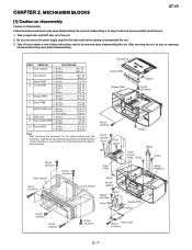
...Tuner PWB Display PWB (D3)x1 (G1)x6 φ3x8mm (A1)x3 φ3x35mm (A1)x2 φ3x10mm Tuner Holder (D1)x2 φ3x10mm 2 - 1 After servicing the unit, be removed when disassembling the unit. Top Cabinet STEP REMOVAL PROCEDURE 1 Front Cabinet 1. MECHANISM BLOCKS QT-V5...sure to protect the optical pickup from the wall outlet before disassembling. Socket G2) x2 3. Flat Cable G3) x1 8 DVD Unit 1. Socket J2) x1 10 Power PWB 1. AQSMECeTuaHrdr-vkViAioce5etPMTaEnuRal2. Take compact disc and DVD disc out of the connector so as to remove the power supply plug from ...
...Tuner PWB Display PWB (D3)x1 (G1)x6 φ3x8mm (A1)x3 φ3x35mm (A1)x2 φ3x10mm Tuner Holder (D1)x2 φ3x10mm 2 - 1 After servicing the unit, be removed when disassembling the unit. Top Cabinet STEP REMOVAL PROCEDURE 1 Front Cabinet 1. MECHANISM BLOCKS QT-V5...sure to protect the optical pickup from the wall outlet before disassembling. Socket G2) x2 3. Flat Cable G3) x1 8 DVD Unit 1. Socket J2) x1 10 Power PWB 1. AQSMECeTuaHrdr-vkViAioce5etPMTaEnuRal2. Take compact disc and DVD disc out of the connector so as to remove the power supply plug from ...
Service Manual
Page 7
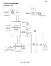
... DVD MOTOR DRIVER FANB024D UU2 ES6603 DVD SERVO CONTROL QT-V5 SW1 POWER SW POWER SUPPLY RECTIFIER DCDC CONVERTER REGULATOR AC TRANS FORMER AC POWER SUPPLY CORD AC 120 V, 60 Hz U3 EEPROM U5 SD RAM U2 FLASH U1 ES6629 MPEGII DECODER DTS DECODER DOLBY DIGITAL DECODER DOLBY PRO LOGIC DECODER WMA DECODER MP3 DECODER TV ENCODER PROGRESSIVE SCAN CVBS-VIDEO VIDEO SW & FILTER JK1 S-VIDEO Cr JK11 Cb COMPONENT OUTPUT AUDIO...
... DVD MOTOR DRIVER FANB024D UU2 ES6603 DVD SERVO CONTROL QT-V5 SW1 POWER SW POWER SUPPLY RECTIFIER DCDC CONVERTER REGULATOR AC TRANS FORMER AC POWER SUPPLY CORD AC 120 V, 60 Hz U3 EEPROM U5 SD RAM U2 FLASH U1 ES6629 MPEGII DECODER DTS DECODER DOLBY DIGITAL DECODER DOLBY PRO LOGIC DECODER WMA DECODER MP3 DECODER TV ENCODER PROGRESSIVE SCAN CVBS-VIDEO VIDEO SW & FILTER JK1 S-VIDEO Cr JK11 Cb COMPONENT OUTPUT AUDIO...
Service Manual
Page 8
... by Digital Multimeter between such a section and the chassis with "Fusible" is a fuse type. • Capacitor: To indicate the unit of the set . In the deck section, a tape is microfarad. In the tuner section, indicates AM indicates FM stereo 2. taining the safety of the capacitor without any symbol is being played back. ( ) indicates the record state. 4. REF. QT-V5 AQSMECeTuaHrd...
... by Digital Multimeter between such a section and the chassis with "Fusible" is a fuse type. • Capacitor: To indicate the unit of the set . In the deck section, a tape is microfarad. In the tuner section, indicates AM indicates FM stereo 2. taining the safety of the capacitor without any symbol is being played back. ( ) indicates the record state. 4. REF. QT-V5 AQSMECeTuaHrd...

Service Manual
Page 10
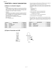
CIRCUIT SCHEMATICS AND PARTS LAYOUT [1] Schematic diagram A DISPLAY PWB-E 220/16 220µH 0.1 4.7/50 B MMBT9014C MMBT9014C 10k 0.1 22P 22P C 10k 10k 10k D E F P5-9 5-F TO G AMP. PWB CN202 SW504 PLAY SW505 SW506 SKIP SKIP UP DOWN SW508 OPEN SW503 STOP SW507 TUNER (BAND) SW502 SW501 VOLUME VOLUME UP DOWN UPD78F9418AGC MICROCOMPUTER H NOTES ON SCHEMATIC DIAGRAM can be found on page 4-1. 1 2 3 4 5 6 Figure 5-1 SCHEMATIC DIAGRAM (1/12) 5 - 1 QT-V5 AQSMECeuTaHrd-rvVkiAioce5etPMTaEnuRal5.
CIRCUIT SCHEMATICS AND PARTS LAYOUT [1] Schematic diagram A DISPLAY PWB-E 220/16 220µH 0.1 4.7/50 B MMBT9014C MMBT9014C 10k 0.1 22P 22P C 10k 10k 10k D E F P5-9 5-F TO G AMP. PWB CN202 SW504 PLAY SW505 SW506 SKIP SKIP UP DOWN SW508 OPEN SW503 STOP SW507 TUNER (BAND) SW502 SW501 VOLUME VOLUME UP DOWN UPD78F9418AGC MICROCOMPUTER H NOTES ON SCHEMATIC DIAGRAM can be found on page 4-1. 1 2 3 4 5 6 Figure 5-1 SCHEMATIC DIAGRAM (1/12) 5 - 1 QT-V5 AQSMECeuTaHrd-rvVkiAioce5etPMTaEnuRal5.

Service Manual
Page 12
QT-V5...TP2 FLAG1 XFLAG3 FLAG2 TP4 RFO TP5 FLAG3 PLL3 CLK SOURCE TESTAD RFO TP6 1 DCLK INPUT DA TP7 TESTAD 0 CRSTAL OSC RFRP DA TP8 ...S0 S1 S2 GND VCC WC SCL SDA 8 7 6 5 GND GND MIRRA CD DVD RR19 OPEN CC27 0.1 RR20 0R SPINDLE FOCUS SLEGN TRACK CC28 0.015 CC29 0R CC30 ...VSSQ 6 12 46 52 VSS VSS VSS 28 41 54 CN04A +5VD FROM DISPLAY P5-2 12-C GND R511 20K 3 IN U8 2 OUT VA6309 1 R42 ...GND 32/64MBIT SDRAM GND GND GND GND H NOTES ON SCHEMATIC DIAGRAM can be found on page 4-1. 1 2 3 4 5 6 Figure 5-3 SCHEMATIC DIAGRAM (3/12) 5 - 3 37 DB3 36 VD33 35 ...
QT-V5...TP2 FLAG1 XFLAG3 FLAG2 TP4 RFO TP5 FLAG3 PLL3 CLK SOURCE TESTAD RFO TP6 1 DCLK INPUT DA TP7 TESTAD 0 CRSTAL OSC RFRP DA TP8 ...S0 S1 S2 GND VCC WC SCL SDA 8 7 6 5 GND GND MIRRA CD DVD RR19 OPEN CC27 0.1 RR20 0R SPINDLE FOCUS SLEGN TRACK CC28 0.015 CC29 0R CC30 ...VSSQ 6 12 46 52 VSS VSS VSS 28 41 54 CN04A +5VD FROM DISPLAY P5-2 12-C GND R511 20K 3 IN U8 2 OUT VA6309 1 R42 ...GND 32/64MBIT SDRAM GND GND GND GND H NOTES ON SCHEMATIC DIAGRAM can be found on page 4-1. 1 2 3 4 5 6 Figure 5-3 SCHEMATIC DIAGRAM (3/12) 5 - 3 37 DB3 36 VD33 35 ...

Service Manual
Page 13
... 1 MULTI Frequency DEFAULT S-CHIP DEFAULT S-CHIP 4.25 4.5 114.75 121.5 reserved 5 NA 135 bypass bypass 27 NA 3.75 4 101.25 108 4.5 4.25 121.5 114.75 reserved 4.75 NA 128.25 3.5 5.5 94.5 148.5 4 6 108 162 FB1 FERB +5VD VCCV VIDEO OUTPUT TABLE VDAC...# LA18 LA19 R320 R340 R350 R370 INSTALL R34, R37 R32, R35 REMOVE R32, R35 R34, R37 TYPE EPROM FLASH LA0 LA1 LA2 LA3 LA4 LA5 LA6... LD6 LD7 +5VD GND LA20 R71 LCS2# R45 RESET# WRLL# 0R OPEN 1 2 3 RESET CLK/CE1 4 WE ADDR/CE1 ROM EMULATOR SOCKET LA21... SCHEMATIC DIAGRAM (4/12) 5 - 4 DCKE/DOE/TDMTSC DWE DB0 DB1
... 1 MULTI Frequency DEFAULT S-CHIP DEFAULT S-CHIP 4.25 4.5 114.75 121.5 reserved 5 NA 135 bypass bypass 27 NA 3.75 4 101.25 108 4.5 4.25 121.5 114.75 reserved 4.75 NA 128.25 3.5 5.5 94.5 148.5 4 6 108 162 FB1 FERB +5VD VCCV VIDEO OUTPUT TABLE VDAC...# LA18 LA19 R320 R340 R350 R370 INSTALL R34, R37 R32, R35 REMOVE R32, R35 R34, R37 TYPE EPROM FLASH LA0 LA1 LA2 LA3 LA4 LA5 LA6... LD6 LD7 +5VD GND LA20 R71 LCS2# R45 RESET# WRLL# 0R OPEN 1 2 3 RESET CLK/CE1 4 WE ADDR/CE1 ROM EMULATOR SOCKET LA21... SCHEMATIC DIAGRAM (4/12) 5 - 4 DCKE/DOE/TDMTSC DWE DB0 DB1

Service Manual
Page 16
...B36 B37 B38 B39 B40 B41 B42 0.1 0.1 0.1 0.1 0.1 0.1 0.1 B RESET# ZERO 7 RESET 8 ZERO 14 BCKIN 13 CAP TBCKR63 33 TBCK GN R 9 12 L VOUTR VOUTL 10 AGND 11 VCC C25 10/16 VCCV P5-10 12B J4 FROM AMP.PWB 1 C CN209 2 3 4 5 6 7 +5VA +5VD +5VD ...MUTE CIRCUIT 5 6 Figure 5-7 SCHEMATIC DIAGRAM (7/12) 5 - 7 R58 33 TW S EAUX01 EAUX00 R503 R523 3 MC 5 MC 3 MD 6 MD 16 SRCIN 15 DIN R67 TSD0- QT-V5 MPEG PWB UNIT (3/3) LL7 FB (0805) +5VA VCC20 VCC33 ES60x8 A U10 DA1132 2-CHANNEL AUDIO OUT R48 4.7K WOLFSON 2-CHANNEL AUDIODAC B55 B61 B9 B10 B11...
...B36 B37 B38 B39 B40 B41 B42 0.1 0.1 0.1 0.1 0.1 0.1 0.1 B RESET# ZERO 7 RESET 8 ZERO 14 BCKIN 13 CAP TBCKR63 33 TBCK GN R 9 12 L VOUTR VOUTL 10 AGND 11 VCC C25 10/16 VCCV P5-10 12B J4 FROM AMP.PWB 1 C CN209 2 3 4 5 6 7 +5VA +5VD +5VD ...MUTE CIRCUIT 5 6 Figure 5-7 SCHEMATIC DIAGRAM (7/12) 5 - 7 R58 33 TW S EAUX01 EAUX00 R503 R523 3 MC 5 MC 3 MD 6 MD 16 SRCIN 15 DIN R67 TSD0- QT-V5 MPEG PWB UNIT (3/3) LL7 FB (0805) +5VA VCC20 VCC33 ES60x8 A U10 DA1132 2-CHANNEL AUDIO OUT R48 4.7K WOLFSON 2-CHANNEL AUDIODAC B55 B61 B9 B10 B11...

Service Manual
Page 18
...TUNER PWB E FM SIGNAL CD SIGNAL 2.2/50 MMBT9014 C 2.2K 10/16 2.2K MMBT9014 C 2.2/50 10/16 10/16 2.2/50 2.2/50 0.1 MMBT9014 C 10/16 2.2/50 0.1 0.1 0.1 0.1 0.1 0.1 2.2/50 0.0027 0.0027 22/16 220/16 MMBT9014 C 10/16 ZD210 8.2V 0.1 AUDIO PROCESSOR 5.6K 5.6K P5-8 8-D TO DVD... SERVO PWB J5 10/16 10/16 8050 C 2.2/50 F 0.1 560 CN02 2.2/50 0.1 47/16 6.2V P5-1 1-G FROM DISPLAY PWB G AC PO A H NOTES ON SCHEMATIC DIAGRAM can be found on page 4-1. 1 2 3 4 5 6 Figure 5-9 SCHEMATIC DIAGRAM (9/12) 5 - 9 QT-V5 A AMP.
...TUNER PWB E FM SIGNAL CD SIGNAL 2.2/50 MMBT9014 C 2.2K 10/16 2.2K MMBT9014 C 2.2/50 10/16 10/16 2.2/50 2.2/50 0.1 MMBT9014 C 10/16 2.2/50 0.1 0.1 0.1 0.1 0.1 0.1 2.2/50 0.0027 0.0027 22/16 220/16 MMBT9014 C 10/16 ZD210 8.2V 0.1 AUDIO PROCESSOR 5.6K 5.6K P5-8 8-D TO DVD... SERVO PWB J5 10/16 10/16 8050 C 2.2/50 F 0.1 560 CN02 2.2/50 0.1 47/16 6.2V P5-1 1-G FROM DISPLAY PWB G AC PO A H NOTES ON SCHEMATIC DIAGRAM can be found on page 4-1. 1 2 3 4 5 6 Figure 5-9 SCHEMATIC DIAGRAM (9/12) 5 - 9 QT-V5 A AMP.

Service Manual
Page 26
...5 1 3 1 CN05A GR 5 YL 4 OR 3 RD 2 BR 1 L-CH SPEAKERS CN01 TO TUNER PWB OR 3 YL 2 GR 1 CN4 TO DVD SERVO PWB SW506 SKIP PU D E F G H 1 SW501 VOLUME DOWN SW502 VOLUME UP SW503 STOP SW504 PLAY SW505 SKIP DOWN 40 41 35 45 30 50 IC301 21 25 55 60 20 15... x 2 ] 2 3 4 5 Figure 5-17 WIRING SIDE OF PWB (5/6) 5 - 17 COLOR TABLE BR BROWN RD(R) RED OR ORANGE YL YELLOW GR GREEN BL BLUE VL VIOLET GY GRAY WH(W) WHITE BK BLACK PK PINK 6 RD BK RD BK BK WH QT-V5 A SWITCH-D B 6 5 4 3 2 1 C SW507 TUNER(BAND) SW508 OPEN/CLOSE CN501 DISPLAY-E 6 1 1 TO AMP.
...5 1 3 1 CN05A GR 5 YL 4 OR 3 RD 2 BR 1 L-CH SPEAKERS CN01 TO TUNER PWB OR 3 YL 2 GR 1 CN4 TO DVD SERVO PWB SW506 SKIP PU D E F G H 1 SW501 VOLUME DOWN SW502 VOLUME UP SW503 STOP SW504 PLAY SW505 SKIP DOWN 40 41 35 45 30 50 IC301 21 25 55 60 20 15... x 2 ] 2 3 4 5 Figure 5-17 WIRING SIDE OF PWB (5/6) 5 - 17 COLOR TABLE BR BROWN RD(R) RED OR ORANGE YL YELLOW GR GREEN BL BLUE VL VIOLET GY GRAY WH(W) WHITE BK BLACK PK PINK 6 RD BK RD BK BK WH QT-V5 A SWITCH-D B 6 5 4 3 2 1 C SW507 TUNER(BAND) SW508 OPEN/CLOSE CN501 DISPLAY-E 6 1 1 TO AMP.
Service Manual
Page 28
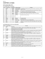
... pins work as feedback inputs for the synchronous power MOSFET. Connected to ground for the application when the inductor current goes negative (Source/Sink), soft-start at least 4 v higher than standard frequency. QT-V5 AQSMECeTuaHrdr-vkViAioce5etPMTaEnuRal6. Setting in Reset Crystal oscillation Crystal oscillation Chip enable Serial data Clock signal Data out SD input IF input OUTPUT AM input FM input Power supply Phase comparison output GROUND Function For generation...
... pins work as feedback inputs for the synchronous power MOSFET. Connected to ground for the application when the inductor current goes negative (Source/Sink), soft-start at least 4 v higher than standard frequency. QT-V5 AQSMECeTuaHrdr-vkViAioce5etPMTaEnuRal6. Setting in Reset Crystal oscillation Crystal oscillation Chip enable Serial data Clock signal Data out SD input IF input OUTPUT AM input FM input Power supply Phase comparison output GROUND Function For generation...

Service Manual
Page 30
... with asterisk mark (*) is (open) terminal which is not connected to the outside. INPUT INPUT INPUT OUTPUT INPUT INPUT INPUT INPUT INPUT INPUT INPUT INPUT INPUT OUTPUT INPUT OUTPUT INPUT OUTPUT OUTPUT OUTPUT OUTPUT OUTPUT -- Analog ground. Supply input voltage. Left channel input 3. Left channel output for left channel input Gain output and input selector for bass controller. Audio processor right channel input. Audio processor left channel. Right rear speaker output. QT-V5 IC205 9HX03523130047: Audio Processor (PT2313L) Pin No. 1 2 3 4 5 6 7 8 9 10* 11 12 13 14...
... with asterisk mark (*) is (open) terminal which is not connected to the outside. INPUT INPUT INPUT OUTPUT INPUT INPUT INPUT INPUT INPUT INPUT INPUT INPUT INPUT OUTPUT INPUT OUTPUT INPUT OUTPUT OUTPUT OUTPUT OUTPUT OUTPUT -- Analog ground. Supply input voltage. Left channel input 3. Left channel output for left channel input Gain output and input selector for bass controller. Audio processor right channel input. Audio processor left channel. Right rear speaker output. QT-V5 IC205 9HX03523130047: Audio Processor (PT2313L) Pin No. 1 2 3 4 5 6 7 8 9 10* 11 12 13 14...
Service Manual
Page 32
... document has been published to replace these parts with " " are subject to change without notice. ASSEMBLY (Not Replacement Item) „ INDEX Parts marked with specified ones for maintaining the safety and performance of the set . Be sure to be used for maintaining the safety of the set . QT-V5 PARTS GUIDE DVD/CD SYSTEM MODEL QT-V5 CONTENTS [1] INTEGRATED CIRCUITS [2] TRANSISTORS [3] DIODES [4] FILTERS [5] TRANSFORMERS [6] COILS [7] VARIABLE...
... document has been published to replace these parts with " " are subject to change without notice. ASSEMBLY (Not Replacement Item) „ INDEX Parts marked with specified ones for maintaining the safety and performance of the set . Be sure to be used for maintaining the safety of the set . QT-V5 PARTS GUIDE DVD/CD SYSTEM MODEL QT-V5 CONTENTS [1] INTEGRATED CIRCUITS [2] TRANSISTORS [3] DIODES [4] FILTERS [5] TRANSFORMERS [6] COILS [7] VARIABLE...

Service Manual
Page 33
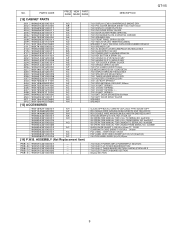
PARTS CODE [1]...PRICE NEW PART RANK MARK RANK DESCRIPTION AM IC BU2616F (FLAT PACK) AM IC LA1823 (SINGLE CHIP TUNER ) AN IC IRF7313 (POWER MOSFET) (SO-8) AN IC IRF7313 (POWER MOSFET) (SO-8) AR IC IRU3048CS (DC-DC CONVERTERCONTROL) (SOIC) AH IC TA8229K 15SIL AL IC PT2313L (4 CHANNEL... FOR DISPLAY (ORANGE) 109x24.5x3.5mm (7 AE DIODE ESD-0603ESDA AE DIODE 1N4148 AE FM TUNING DIODE 1SV101 AE FM TUNING DIODE 1SV101 AG AM TUNING DIODE ... 100V/3A AE DIODE 1N5401 100V/3A AE DIODE 1N5401 100V/3A AC LED RED DIA 3mm (7811B) (LONG LEAD 30mm) AC ZENER DIODE+-5% 11V AC ZENER...
PARTS CODE [1]...PRICE NEW PART RANK MARK RANK DESCRIPTION AM IC BU2616F (FLAT PACK) AM IC LA1823 (SINGLE CHIP TUNER ) AN IC IRF7313 (POWER MOSFET) (SO-8) AN IC IRF7313 (POWER MOSFET) (SO-8) AR IC IRU3048CS (DC-DC CONVERTERCONTROL) (SOIC) AH IC TA8229K 15SIL AL IC PT2313L (4 CHANNEL... FOR DISPLAY (ORANGE) 109x24.5x3.5mm (7 AE DIODE ESD-0603ESDA AE DIODE 1N4148 AE FM TUNING DIODE 1SV101 AE FM TUNING DIODE 1SV101 AG AM TUNING DIODE ... 100V/3A AE DIODE 1N5401 100V/3A AE DIODE 1N5401 100V/3A AC LED RED DIA 3mm (7811B) (LONG LEAD 30mm) AC ZENER DIODE+-5% 11V AC ZENER...

Service Manual
Page 38
... (COMPLETE SETS) RELAY : DC12V SPEAKER SPEAKER PUSH SW EX-13G (Q)13 [Power] TACT SW 6x6mm H4.3 [Volume Down] TACT SW 6x6mm H4.3 [Volume Up] TACT SW 6x6mm H4.3 [Stop] TACT SW 6x6mm H4.3 [Play] TACT SW 6x6mm H4.3 [Skip Down] TACT SW 6x6mm H4.3 [Skip Up] TACT SW 6x6mm H4.3 [Tuner (Band)] TACT SW 6x6mm H4.3 [Open/Close] QT-V5...
... (COMPLETE SETS) RELAY : DC12V SPEAKER SPEAKER PUSH SW EX-13G (Q)13 [Power] TACT SW 6x6mm H4.3 [Volume Down] TACT SW 6x6mm H4.3 [Volume Up] TACT SW 6x6mm H4.3 [Stop] TACT SW 6x6mm H4.3 [Play] TACT SW 6x6mm H4.3 [Skip Down] TACT SW 6x6mm H4.3 [Skip Up] TACT SW 6x6mm H4.3 [Tuner (Band)] TACT SW 6x6mm H4.3 [Open/Close] QT-V5...
Service Manual
Page 40
... LOAD DECK 7321 DISPLAY BRACKET MOULD BLK 7321 SPACER LED MOULD MIKLY 7321 TUNER HOLDER MOULD GRY 7321 HOLDER LOCK MOULD GRY 7231 4.5V BATT SPRING + 7321 ROD ANTENNA 4 ...WIRE AWG#26,2M,BLK,W/BOTH END RED & WHT W=B G/B SHARP QT-V518.7/8x13.1/2x9.1/2" I /B OPERATION MANUAL FOR CANADA FROM SERIAL NO. 4xx00501 QUICK GUIDE SHARP Y-160 (W)x (H)mm TT: PAGE GUARRANTY CARD SHRAP Y-160 (H)x (W)mm FCC LABEL : B/W73 (W)x41 (H)mm POP LABEL (DVD VIDEO) SHARP (QT-V5) 120 (W)x28 (H) CAUTION LABEL: B/W32 (H)x12 (W)mm 7321 ELECT POWER AMP & POWERSPPLY SECTION : 7321 ELECT AC POWER BOARDSECTION : 7321 ELECT TUNER...
... LOAD DECK 7321 DISPLAY BRACKET MOULD BLK 7321 SPACER LED MOULD MIKLY 7321 TUNER HOLDER MOULD GRY 7321 HOLDER LOCK MOULD GRY 7231 4.5V BATT SPRING + 7321 ROD ANTENNA 4 ...WIRE AWG#26,2M,BLK,W/BOTH END RED & WHT W=B G/B SHARP QT-V518.7/8x13.1/2x9.1/2" I /B OPERATION MANUAL FOR CANADA FROM SERIAL NO. 4xx00501 QUICK GUIDE SHARP Y-160 (W)x (H)mm TT: PAGE GUARRANTY CARD SHRAP Y-160 (H)x (W)mm FCC LABEL : B/W73 (W)x41 (H)mm POP LABEL (DVD VIDEO) SHARP (QT-V5) 120 (W)x28 (H) CAUTION LABEL: B/W32 (H)x12 (W)mm 7321 ELECT POWER AMP & POWERSPPLY SECTION : 7321 ELECT AC POWER BOARDSECTION : 7321 ELECT TUNER...
Service Manual
Page 45
... Cylindrical type (without lead wire) VC MN Cylindrical type (without lead wire) VC TV Square type (without lead wire) VC TQ Square type (without lead wire) VC CY Square type (without lead wire) VC CZ Square type (without lead wire) VR J.. QT-V5 ̌HOW TO ORDER REPLACEMENT PARTS̍ To have your nearest SHARP Parts Distributor to replace parts with ̌ ̍are...
... Cylindrical type (without lead wire) VC MN Cylindrical type (without lead wire) VC TV Square type (without lead wire) VC TQ Square type (without lead wire) VC CY Square type (without lead wire) VC CZ Square type (without lead wire) VR J.. QT-V5 ̌HOW TO ORDER REPLACEMENT PARTS̍ To have your nearest SHARP Parts Distributor to replace parts with ̌ ̍are...


