Service Manual
Page 1
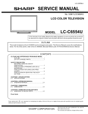
... performance of user-safety (Required by safety regulations in some parts. SY7C3LC65D64U) Service Manual. DIMENSIONS [1] DIMENSIONS 3-1 CHAPTER 4. This document has been published to the LC-65D64U (Revised Edition) (No. SPECIFICATIONS [1] SPECIFICATIONS 1-1 CHAPTER 2. For the other points, refer to be restored to its original condition and only parts identical to change without notice. TopPage LC-C6554U SERVICE MANUAL No. OPERATION MANUAL [1] OPERATION MANUAL 2-1 CHAPTER 3. S38I1LCC6554U LCD COLOR TELEVISION MODEL LC-C6554U In the interests of the set.
... performance of user-safety (Required by safety regulations in some parts. SY7C3LC65D64U) Service Manual. DIMENSIONS [1] DIMENSIONS 3-1 CHAPTER 4. This document has been published to the LC-65D64U (Revised Edition) (No. SPECIFICATIONS [1] SPECIFICATIONS 1-1 CHAPTER 2. For the other points, refer to be restored to its original condition and only parts identical to change without notice. TopPage LC-C6554U SERVICE MANUAL No. OPERATION MANUAL [1] OPERATION MANUAL 2-1 CHAPTER 3. S38I1LCC6554U LCD COLOR TELEVISION MODEL LC-C6554U In the interests of the set.
Service Manual
Page 2
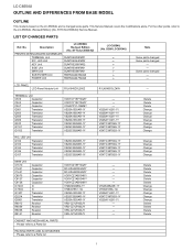
...-1Q VS2SA1162Y/-1Y VSKTC3875SG-1Y VS2SA1162Y/-1Y - - - - LIST OF CHANGED PARTS LC-65D64U Ref. Some parts changed - - LCD PANEL LCD Panel Module Unit R1LK645D3LZ40Z R1LK645D3LZ40V - No. LC-C6554U LOCU-C6T5L54IUNE AND DIFFERENCES FROM BASE MSOerDvEicLe Manual OUTLINE This model is based on the LC-65D64U and is changed some parts. This Service Manual covers the modifications alone. SY7C3LC65D64U) PRINTED WIRING BOARD ASSEMBLIES TERMINAL Unit DUNTKE208FM01 R/C, LED Unit DUNTKE264FM02 KEY Unit DUNTKE266FM02 SIDE Unit...
...-1Q VS2SA1162Y/-1Y VSKTC3875SG-1Y VS2SA1162Y/-1Y - - - - LIST OF CHANGED PARTS LC-65D64U Ref. Some parts changed - - LCD PANEL LCD Panel Module Unit R1LK645D3LZ40Z R1LK645D3LZ40V - No. LC-C6554U LOCU-C6T5L54IUNE AND DIFFERENCES FROM BASE MSOerDvEicLe Manual OUTLINE This model is based on the LC-65D64U and is changed some parts. This Service Manual covers the modifications alone. SY7C3LC65D64U) PRINTED WIRING BOARD ASSEMBLIES TERMINAL Unit DUNTKE208FM01 R/C, LED Unit DUNTKE264FM02 KEY Unit DUNTKE266FM02 SIDE Unit...
Service Manual
Page 3
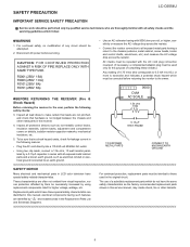
LSCA-CF65E54TUY PRECAUTION Service Manual LC-C6554U IMPORTANT SERVICE SAFETY PRECAUTION Service work should be attempted. 2. Disconnect AC power before returning the monitor to the owner. „BEFORE RETURNING THE RECEIVER (Fire & Shock Hazard) Before returning the receiver to those used only for higher voltage, wattage, etc. Inspect all protective devices such as the factory recommended replacement parts shown in this service manual, may create shock, fire or other...
LSCA-CF65E54TUY PRECAUTION Service Manual LC-C6554U IMPORTANT SERVICE SAFETY PRECAUTION Service work should be attempted. 2. Disconnect AC power before returning the monitor to the owner. „BEFORE RETURNING THE RECEIVER (Fire & Shock Hazard) Before returning the receiver to those used only for higher voltage, wattage, etc. Inspect all protective devices such as the factory recommended replacement parts shown in this service manual, may create shock, fire or other...
Service Manual
Page 5
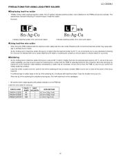
... every use , file it . Repairing with conventional lead wire solder may be easily corroded. The LF symbol indicates lead-free solder, and is blackened during use of this model employs lead-free solder. PRECAUTIONS FOR USING LEAD-FREE SOLDER LC-C6554U „Employing lead-free solder • "PWBs" of it with steel wool or fine sandpaper. • Be careful when replacing parts with...
... every use , file it . Repairing with conventional lead wire solder may be easily corroded. The LF symbol indicates lead-free solder, and is blackened during use of this model employs lead-free solder. PRECAUTIONS FOR USING LEAD-FREE SOLDER LC-C6554U „Employing lead-free solder • "PWBs" of it with steel wool or fine sandpaper. • Be careful when replacing parts with...
Service Manual
Page 6
LC-C6554U PRECAUTIONS IN SERVICING THE HDCP-KEY ROM Applied part: HDCP-KEY ROM IC8451 RH-IXC318WJQZY (updated ROM) The HDCP-KEY ROM shall be protected and managed for its information inside. In servicing this ROM, therefore, take the following information protection/management measures. 1) When disposing of the component parts and PWBs, destruct the IC itself in a proper way...
LC-C6554U PRECAUTIONS IN SERVICING THE HDCP-KEY ROM Applied part: HDCP-KEY ROM IC8451 RH-IXC318WJQZY (updated ROM) The HDCP-KEY ROM shall be protected and managed for its information inside. In servicing this ROM, therefore, take the following information protection/management measures. 1) When disposing of the component parts and PWBs, destruct the IC itself in a proper way...
Service Manual
Page 7
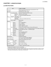
...) Weight TV + stand TV only 121.3 lbs./55.0 kg 110.3 lbs./50.0 kg Dimension*2 (W H D) TV + stand TV only Operating temperature 6011/64 40 157/8 inch 6011/64 3711/64 37/8 inch 32°F to 104°F (0°C to 40°C) *1 Emergency alert messages via Cable are unreceivable. *2 The dimensional drawings are nominal values of production units. SPECIFICATIONS [1] SPECIFICATIONS Service Manual LC-C6554U Item Model: LC-C6554U LCD panel 65" screen size class Advanced Super View & BLACK TFT LCD (Diagonal...
...) Weight TV + stand TV only 121.3 lbs./55.0 kg 110.3 lbs./50.0 kg Dimension*2 (W H D) TV + stand TV only Operating temperature 6011/64 40 157/8 inch 6011/64 3711/64 37/8 inch 32°F to 104°F (0°C to 40°C) *1 Emergency alert messages via Cable are unreceivable. *2 The dimensional drawings are nominal values of production units. SPECIFICATIONS [1] SPECIFICATIONS Service Manual LC-C6554U Item Model: LC-C6554U LCD panel 65" screen size class Advanced Super View & BLACK TFT LCD (Diagonal...
Service Manual
Page 8
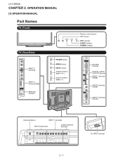
LC-C6554U LCC-HC6A554PUTER 2. OPERATION MANUAL [1] OPERATION MANUAL Service Manual Part Names TV (Front) TV (Rear/Side) Remote control sensor OPC sensor OPC indicator SLEEP indicator POWER indicator INPUT 3 terminals INPUT 4 terminal (HDMI) SERVICE terminal POWER button MENU button INPUT button Channel buttons (CH / ) Volume buttons (VOL / ) RS-232C terminal DIGITAL AUDIO OUTPUT terminal INPUT 5 terminal (HDMI) INPUT 6 terminals (HDMI) INPUT 7 terminals (PC-IN) Antenna/Cable in INPUT 1 terminals INPUT 2 terminals AUDIO OUTPUT terminals AC INPUT terminal 2 - 1
LC-C6554U LCC-HC6A554PUTER 2. OPERATION MANUAL [1] OPERATION MANUAL Service Manual Part Names TV (Front) TV (Rear/Side) Remote control sensor OPC sensor OPC indicator SLEEP indicator POWER indicator INPUT 3 terminals INPUT 4 terminal (HDMI) SERVICE terminal POWER button MENU button INPUT button Channel buttons (CH / ) Volume buttons (VOL / ) RS-232C terminal DIGITAL AUDIO OUTPUT terminal INPUT 5 terminal (HDMI) INPUT 6 terminals (HDMI) INPUT 7 terminals (PC-IN) Antenna/Cable in INPUT 1 terminals INPUT 2 terminals AUDIO OUTPUT terminals AC INPUT terminal 2 - 1
Service Manual
Page 9
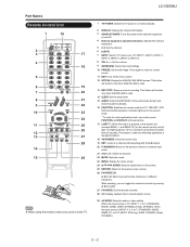
LC-C6554U 1 TV POWER: Switch the TV power on or enters standby. 2 DISPLAY: Display the channel information. 3 SOURCE POWER: Turns the power of the external equipment on and off if no operations are performed within about 5 seconds. While watching, you need to normal screen. 11 EXIT: Turn off the menu screen. 12 OPTION: Display the AQUOS LINK MENU screen. Indicator lights up for the current mode. * To enter the code registration mode, you can toggle the selected channels by pressing A, B, C and...
LC-C6554U 1 TV POWER: Switch the TV power on or enters standby. 2 DISPLAY: Display the channel information. 3 SOURCE POWER: Turns the power of the external equipment on and off if no operations are performed within about 5 seconds. While watching, you need to normal screen. 11 EXIT: Turn off the menu screen. 12 OPTION: Display the AQUOS LINK MENU screen. Indicator lights up for the current mode. * To enter the code registration mode, you can toggle the selected channels by pressing A, B, C and...
Service Manual
Page 10
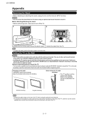
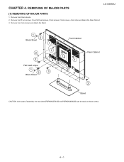
... TV, and then use the screws supplied with the bracket before beginning work , make sure to turn off the TV. 1 2 Unfasten the four screws used to do the work themselves. Setting the TV on the rear of other wall mount brackets may result in reverse order. LC-C6554U Appendix Removing the Stand Before detaching (or attaching) the stand, unplug the AC cord from the TV. Customers should be performed by qualified service personnel. Detach the stand...
... TV, and then use the screws supplied with the bracket before beginning work , make sure to turn off the TV. 1 2 Unfasten the four screws used to do the work themselves. Setting the TV on the rear of other wall mount brackets may result in reverse order. LC-C6554U Appendix Removing the Stand Before detaching (or attaching) the stand, unplug the AC cord from the TV. Customers should be performed by qualified service personnel. Detach the stand...
Service Manual
Page 11
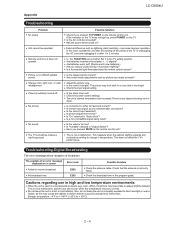
LC-C6554U Appendix Troubleshooting Problem No power Unit cannot be operated. Picture is cut off . No picture No sound The TV sometimes makes a cracking sound. Has the power been turned on the TV. Are batteries inserted with sidebar screen. Are batteries worn out? (Replace with new batteries.) Are you pressed TV POWER on the remote control unit? Adjust the picture tone. Is the sleep timer set correctly? Is the correct input selected? Is a non-compatible signal being input? This does...
LC-C6554U Appendix Troubleshooting Problem No power Unit cannot be operated. Picture is cut off . No picture No sound The TV sometimes makes a cracking sound. Has the power been turned on the TV. Are batteries inserted with sidebar screen. Are batteries worn out? (Replace with new batteries.) Are you pressed TV POWER on the remote control unit? Adjust the picture tone. Is the sleep timer set correctly? Is the correct input selected? Is a non-compatible signal being input? This does...
Service Manual
Page 12
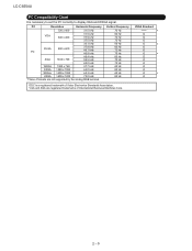
LC-C6554U PC Compatibility Chart It is a registered trademark of International Business Machines Corp. VESA Standard * O O O O * O O O * O O O O O O * O 2 - 5 PC Resolution... 65.3 kHz UXGA 1600 x 1200 75.0 kHz *These 4 formats are registered trademarks of Video Electronics Standards Association. VGA and XGA are not supported by the analog ...RGB terminal. Vertical Frequency 70 Hz 60 Hz 72 Hz 75 Hz 56 Hz 60 Hz 72 Hz 75 Hz 60 Hz 70 Hz 75 Hz 60 Hz 60 Hz 60 Hz 60 Hz DDC is necessary to set the PC correctly to display XGA and WXGA signal...
LC-C6554U PC Compatibility Chart It is a registered trademark of International Business Machines Corp. VESA Standard * O O O O * O O O * O O O O O O * O 2 - 5 PC Resolution... 65.3 kHz UXGA 1600 x 1200 75.0 kHz *These 4 formats are registered trademarks of Video Electronics Standards Association. VGA and XGA are not supported by the analog ...RGB terminal. Vertical Frequency 70 Hz 60 Hz 72 Hz 75 Hz 56 Hz 60 Hz 72 Hz 75 Hz 60 Hz 70 Hz 75 Hz 60 Hz 60 Hz 60 Hz 60 Hz DDC is necessary to set the PC correctly to display XGA and WXGA signal...
Service Manual
Page 13
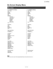
Program Title Display Favorite CH Game Play Time Operation Lock Out Digital Setup Menu Audio Setup Identification Software Update For HDMI/PC-IN Mode Picture Menu OPC Backlight Contrast Brightness Color Tint Sharpness Advanced C.M.S.-Hue C.M.S.-Saturation Color Temp. LC-C6554U 2 - 6 Active Contrast Fine Motion I /P Setting Film Mode 3D-Y/C Monochrome Range of OPC Reset Audio Menu Treble Bass Balance Surround Bass Enhancer Reset Power Control Menu No Signal Off No Operation Off Setup Menu Input Skip Input Signal Auto Sync. Position Language Reset Option Menu AQUOS LINK Setup Audio Only ...
Program Title Display Favorite CH Game Play Time Operation Lock Out Digital Setup Menu Audio Setup Identification Software Update For HDMI/PC-IN Mode Picture Menu OPC Backlight Contrast Brightness Color Tint Sharpness Advanced C.M.S.-Hue C.M.S.-Saturation Color Temp. LC-C6554U 2 - 6 Active Contrast Fine Motion I /P Setting Film Mode 3D-Y/C Monochrome Range of OPC Reset Audio Menu Treble Bass Balance Surround Bass Enhancer Reset Power Control Menu No Signal Off No Operation Off Setup Menu Input Skip Input Signal Auto Sync. Position Language Reset Option Menu AQUOS LINK Setup Audio Only ...
Service Manual
Page 15
Remove the 20 lock screws, 2 lock flat head screws, 2 lock screws, 2 lock screws, 4 lock clips and detach the Rear Cabinet. 3. Remove the 6 black sheets. 2. Remove the 4 lock screws and detach the Stand. 1 2 Black Sheet 1 1 2 2 Flat head screw 1 2 3 Black Sheet Front Cabinet 1 1 Rear Cabinet 2 Stand CAUTION: In the case of assembly, the new sheet (PSPAKA237WJ00 and PSPAGA386WJ00) can be stuck on these screws. 4 - 1 REMOVING OF MAJOR PARSTeSrvice Manual LC-C6554U [1] REMOVING OF MAJOR PARTS 1. LCC-HC6A554PUTER 4.
Remove the 20 lock screws, 2 lock flat head screws, 2 lock screws, 2 lock screws, 4 lock clips and detach the Rear Cabinet. 3. Remove the 6 black sheets. 2. Remove the 4 lock screws and detach the Stand. 1 2 Black Sheet 1 1 2 2 Flat head screw 1 2 3 Black Sheet Front Cabinet 1 1 Rear Cabinet 2 Stand CAUTION: In the case of assembly, the new sheet (PSPAKA237WJ00 and PSPAGA386WJ00) can be stuck on these screws. 4 - 1 REMOVING OF MAJOR PARSTeSrvice Manual LC-C6554U [1] REMOVING OF MAJOR PARTS 1. LCC-HC6A554PUTER 4.
Service Manual
Page 20
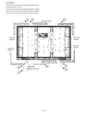
LC-C6554U 21.Remove the 2 lock screws and detach the LCD Panel Module. 22.Remove the R/C, LED Unit. 23.Remove the 12 lock screws and detach the Panel Fix Angle-B. 24.Remove the 10 lock screws and detach the Panel Fix Angle-C. 25.Remove the 12 lock screws and detach the Panel Fix Angle. 23 25 23 Panel Fix Angle Panel Fix Angle-B Panel Fix Angle-C Panel Fix Angle 24 25 22 R/C, LED Unit 21 Panel Fix Angle-B Panel Fix Angle-C 24 21 4 - 6
LC-C6554U 21.Remove the 2 lock screws and detach the LCD Panel Module. 22.Remove the R/C, LED Unit. 23.Remove the 12 lock screws and detach the Panel Fix Angle-B. 24.Remove the 10 lock screws and detach the Panel Fix Angle-C. 25.Remove the 12 lock screws and detach the Panel Fix Angle. 23 25 23 Panel Fix Angle Panel Fix Angle-B Panel Fix Angle-C Panel Fix Angle 24 25 22 R/C, LED Unit 21 Panel Fix Angle-B Panel Fix Angle-C 24 21 4 - 6
Service Manual
Page 21
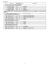
... the safety of the set . PartsGuide LC-C6554U PARTS GUIDE No. MODEL CONTENTS LC-C6554U [1] PRINTED WIRING BOARD ASSEMBLIES [2] LCD PANEL (NOTE: THE PARTS HERE SHOWN ARE SUPPLIED AS AN ASSEMBLY BUT NOT INDEPENDENTLY.) [3] DUNTKE208FM01 (TERMINAL Unit) [4] DUNTKE264FM02 (R/C, LED Unit) [5] DUNTKE558FM01 (MAIN Unit) [6] NOTE (Conductive cloth tape) [7] NOTE (Temperature-proof cover) [8] CABINET AND MECHANICAL PARTS [9] SUPPLIED ACCESSORIES [10] PACKING PARTS (NOT REPLACEMENT ITEM) [11] SERVICE JIG (USE FOR SERVICING) Parts marked with specified...
... the safety of the set . PartsGuide LC-C6554U PARTS GUIDE No. MODEL CONTENTS LC-C6554U [1] PRINTED WIRING BOARD ASSEMBLIES [2] LCD PANEL (NOTE: THE PARTS HERE SHOWN ARE SUPPLIED AS AN ASSEMBLY BUT NOT INDEPENDENTLY.) [3] DUNTKE208FM01 (TERMINAL Unit) [4] DUNTKE264FM02 (R/C, LED Unit) [5] DUNTKE558FM01 (MAIN Unit) [6] NOTE (Conductive cloth tape) [7] NOTE (Temperature-proof cover) [8] CABINET AND MECHANICAL PARTS [9] SUPPLIED ACCESSORIES [10] PACKING PARTS (NOT REPLACEMENT ITEM) [11] SERVICE JIG (USE FOR SERVICING) Parts marked with specified...
Service Manual
Page 22
PARTS CODE PRICE NEW PART RANK MARK DELIVERY DESCRIPTION [1] PRINTED WIRING BOARD ASSEMBLIES N DUNTKE208FM01 N DUNTKE264FM02 N DUNTKE266FM02 N DUNTKE488FM01 N DUNTKE558FM01 N RDENCA246WJQZ N RDENCA247WJQZ BH AP AG N BB N CB N BW N BT N X TERMINAL Unit X R/C, LED Unit X KEY Unit X SIDE Unit X MAIN Unit X SUB POWER Unit X POWER Unit [2] LCD PANEL (NOTE: THE PARTS HERE SHOWN ARE SUPPLIED AS AN ASSEMBLY BUT NOT INDEPEN- DENTLY.) N R1LK645D3LZ40V ** N [3] DUNTKE208FM01 (TERMINAL Unit) J 65" LCD Panel... J Transistor, 2SA1162-Y(TE85L,F)/(T5L,F,T) 2 LC-C6554U NO.
PARTS CODE PRICE NEW PART RANK MARK DELIVERY DESCRIPTION [1] PRINTED WIRING BOARD ASSEMBLIES N DUNTKE208FM01 N DUNTKE264FM02 N DUNTKE266FM02 N DUNTKE488FM01 N DUNTKE558FM01 N RDENCA246WJQZ N RDENCA247WJQZ BH AP AG N BB N CB N BW N BT N X TERMINAL Unit X R/C, LED Unit X KEY Unit X SIDE Unit X MAIN Unit X SUB POWER Unit X POWER Unit [2] LCD PANEL (NOTE: THE PARTS HERE SHOWN ARE SUPPLIED AS AN ASSEMBLY BUT NOT INDEPEN- DENTLY.) N R1LK645D3LZ40V ** N [3] DUNTKE208FM01 (TERMINAL Unit) J 65" LCD Panel... J Transistor, 2SA1162-Y(TE85L,F)/(T5L,F,T) 2 LC-C6554U NO.
Service Manual
Page 26
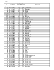
... N AQ N AH N BA N AB X Front Cabinet Ass'y - Spacer, x6 - Operation Button J 65" LCD Panel Module Unit X Control Shield Ass'y - MAIN Shield X Spacer X Bottom Cover, x2 X Support Front Cover X Support Rear Cover X VESA Cover, x4 X Terminal Label X Model Label X Terminal Side Angle X Terminal Bottom Angle X Mini AV Angle X Panel Fix Angle, x2 X Panel Fix Angle-Top, x2 X Panel Fix Angle-C, x2 X Radiator Angle X Main Chassis J Wire Holder, x4...
... N AQ N AH N BA N AB X Front Cabinet Ass'y - Spacer, x6 - Operation Button J 65" LCD Panel Module Unit X Control Shield Ass'y - MAIN Shield X Spacer X Bottom Cover, x2 X Support Front Cover X Support Rear Cover X VESA Cover, x4 X Terminal Label X Model Label X Terminal Side Angle X Terminal Bottom Angle X Mini AV Angle X Panel Fix Angle, x2 X Panel Fix Angle-Top, x2 X Panel Fix Angle-C, x2 X Radiator Angle X Main Chassis J Wire Holder, x4...
Service Manual
Page 27
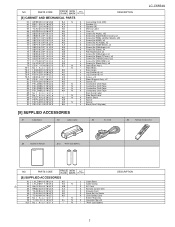
... X6 TCAUHA352WJZZ AD X Quick Set Up Guide X7 TCAUHA367WJZZ AD X Child Safety Card X8 Not Available - N - "AAA" Size Battery DESCRIPTION 7 Side Serial Label X Barrier Sheet X Spacer X Spacer J Bond (One 150g tube) LC-C6554U [9] SUPPLIED ACCESSORIES X1 Cable Band X2 Cable Clamp X3 AC Cord X4 Remote Control Unit X9 Operation Manual X10 "AAA" Size Battery NO. Extend Warranty X9 TINS-D741WJZZ AL N X Operation Manual X10 Not Available - Stand Base J Base Angle J Leg...
... X6 TCAUHA352WJZZ AD X Quick Set Up Guide X7 TCAUHA367WJZZ AD X Child Safety Card X8 Not Available - N - "AAA" Size Battery DESCRIPTION 7 Side Serial Label X Barrier Sheet X Spacer X Spacer J Bond (One 150g tube) LC-C6554U [9] SUPPLIED ACCESSORIES X1 Cable Band X2 Cable Clamp X3 AC Cord X4 Remote Control Unit X9 Operation Manual X10 "AAA" Size Battery NO. Extend Warranty X9 TINS-D741WJZZ AL N X Operation Manual X10 Not Available - Stand Base J Base Angle J Leg...
Service Manual
Page 29
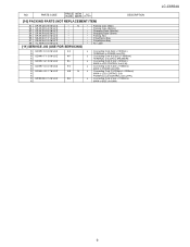
...) to SPEAKERS J Connecting Cord (41pin L=600mm) MAIN to LCD CONTROL Unit (LW) J Connecting Cord (12pin L=1000mm) MAIN to POWER Unit (PD) J Connecting Cord (12-20/4pin L=1000mm) MAIN to LCD CONTROL Unit/ POWER to LCD CONTROL Unit (LP/PL) J Connecting Cord (21pin L=1000mm) MAIN to SIDE Unit (HM) LC-C6554U 9 NO. Polyethylene Bag Polyethylene Bag No. N - - - - - - - - - - - - - - - [11] SERVICE JIG (USE FOR SERVICING) Packing Case (Main) Packing Case (Bottom) Wrapping Paper (Monitor) Wrapping Paper (Stand...
...) to SPEAKERS J Connecting Cord (41pin L=600mm) MAIN to LCD CONTROL Unit (LW) J Connecting Cord (12pin L=1000mm) MAIN to POWER Unit (PD) J Connecting Cord (12-20/4pin L=1000mm) MAIN to LCD CONTROL Unit/ POWER to LCD CONTROL Unit (LP/PL) J Connecting Cord (21pin L=1000mm) MAIN to SIDE Unit (HM) LC-C6554U 9 NO. Polyethylene Bag Polyethylene Bag No. N - - - - - - - - - - - - - - - [11] SERVICE JIG (USE FOR SERVICING) Packing Case (Main) Packing Case (Bottom) Wrapping Paper (Monitor) Wrapping Paper (Stand...

Service Manual
Page 30
LC-C6554U COPYRIGHT 2008 BY SHARP CORPORATION ALL RIGHTS RESERVED. Jun. 2008 TQ2517-S MI. No part of this publication may be reproduced, stored in a retrieval system, or transmitted in any form or by any means, electronic, mechanical, photocopying, recording, or otherwise, without prior written permission of the publisher. KD SHARP CORPORATION AV Systems Group CS Promotion Center Yaita, Tochigi 329-2193, Japan
LC-C6554U COPYRIGHT 2008 BY SHARP CORPORATION ALL RIGHTS RESERVED. Jun. 2008 TQ2517-S MI. No part of this publication may be reproduced, stored in a retrieval system, or transmitted in any form or by any means, electronic, mechanical, photocopying, recording, or otherwise, without prior written permission of the publisher. KD SHARP CORPORATION AV Systems Group CS Promotion Center Yaita, Tochigi 329-2193, Japan


